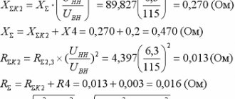
External characteristics of the EMF source
The external characteristic reflects the dependence of the voltage at the source terminals on the load value - the source current specified by the load.
The voltage at the source terminals is less than the EMF by the amount of voltage drop across the internal resistance of the source (1): This equation corresponds to the external characteristic of the EMF source (Fig. 1). built on two points:
Obviously, the voltage at the terminals of the EMF source is greater, the lower its internal resistance.
In an ideal EMF source R0=0, U=E (voltage does not depend on the load). However, when analyzing and calculating a circuit, it is not always convenient to represent the source of electrical energy as a source of EMF. If the internal resistance of the source significantly exceeds the external resistance of the circuit, which, for example, occurs in electronics, then we obtain that the current in the circuit I=U/(R+R0) and at R0>>R is practically independent of the load resistance. In this case, the energy source is represented as a current source.
Let's divide equation (1) by R0 (2):
Equation (2) corresponds to the equivalent circuit shown in Fig. 2. Here Iв=U/R0 and Ik=E/R0, I= Ik - Iв then (3)
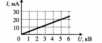
For an ideal current source Rс = ∞. The current-voltage characteristics of real and ideal current sources are shown in Fig. 3.
When there is no clear distinction between the values of R and R0, either an EMF source or a current source can be used as the calculated equivalent of the energy source. In the latter case, expression (3) is used to determine the voltage drop.
Source operating modes
The source can operate in the following modes:
1. Nominal mode is the operating mode for which the source is designed by the manufacturer. For this mode, the source passport indicates the rated current Inom and the rated voltage Unom or power Pnom.
2. Idle mode. In this mode, the external circuit is disconnected from the source, the source current I = 0 and, therefore, the voltage at the source terminals is the open circuit voltage Uхх = E - see equation (1).
3. Short circuit mode. The resistance of the circuit external to the source is zero. The source current is limited only by its internal resistance. From equation (1) at U=0 we obtain I = Iкз = U / R0. To reduce energy losses in the source, the EMF R0 should be as small as possible, and in an ideal source, R0 = 0. Taking this into account, Is >> In is unacceptable for the source.
Sources of electrical energy. External characteristics
to contents
In AC circuits, as well as in DC circuits, there must be sources of electrical energy. The only difference between these sources is that the emf or currents they create are sinusoidal functions of time.
Sources are divided into ideal and real
.
Ideal sources have no internal resistance or conductivity. The EMF or current they create is determined only by the source parameters. In an electrical circuit with ideal sources, the magnitude of the current through the EMF source or the voltage across the current source is determined by the load
.
On electrical diagrams they are depicted in exactly the same way as direct current sources, but the arrows in the symbol indicate the direction taken
for the positive.
Real sources of electrical energy have internal resistance Z
or conductivity
Y
(Fig. 1).
However, on alternating current these quantities are generally complex
.
Just like with direct current, a real source can be represented by two equivalent circuits with an EMF source or a current source. Internal resistance, conductivity and source parameters are interconnected by relationships
| Y = 1/ | (1) |
formally identical to the corresponding expressions for direct current sources. The EMF and current of internal sources correspond to the output voltage in no-load mode and the current in short-circuit mode.
TASK 1
For AC sources it is impossible to construct a current-voltage characteristic. Its role is played by external characteristics
, i.e.,
the dependence of the effective value of the voltage at the output of the source on the magnitude of the effective value of the current in the load, at a constant value of the phase shift angle in the load j
n
.
Let's consider an electrical circuit consisting of a real source and a general load (Fig. 2). The current in the load according to Ohm's law can be determined from the expression
| . | (2) |
Hence, the voltage drop across the load
| , | (3) |
where is the complex relative load resistance
.
The voltage drop in the load can be represented in relative units if we choose the source emf as the base value. Then the complex relative stress in the load
from expression (3) it will be -
| . | (4) |
I is chosen as the base value
short =
E
/
Zs
.
Hence the complex relative current -
| . | (5) |
The modulus of the complex relative current or simply the relative current can be obtained by determining the modulus of the denominator of expression (5) from the expression for the complex relative resistance, in the form
| . | (6) |
From expression (2) taking into account (6), the relative voltage in the load will be
| . | (7) |
Expressions (6) and (7) allow us to construct an external characteristic of the source
electrical energy in relative units, if we take the module of the complex relative load resistance z as a variable, provided that its argument d is constant.
External characteristics for the relative load resistance, varying within 0 < z <µ, for four values of the difference between the angles φ of the load and the internal resistance of the source are plotted in Fig. 3. The use of relative units allows you to analyze the patterns of functions without regard to specific parameter values. Any source of electrical energy in idle mode has an output voltage equal to the EMF of the internal source, and in short circuit mode, the output current is equal to the current of the internal current source. Any real source also has a finite value of internal resistance, which makes it possible to correlate it with the load resistance and obtain, for a load resistance varying in the range from zero to infinity, a change in the relative resistance z in the same range. Therefore, the choice of the indicated values as base values for relative units allows us to extend the conclusions from the analysis of external characteristics to any real source for all possible load cases.
From expressions (6) and (7) it follows that under certain conditions the relative load voltage and current can have a value greater than unity. This means that greater than the short-circuit current can flow through the load.
source and there is a voltage
greater than the emf of the source
. Let's define these conditions.
For relative current i, the condition i > 1.0 is reduced to the condition, and for the relative voltage u - to the condition -. From here we obtain the following conditions for current and voltage, respectively:
| And | (8) |
| . | (9) |
Since 0 < z <µ , then relations (8) and (9) will be satisfied only for
|d |
>p /2 , if this condition is met, then there will always be values of z for which these expressions will be valid
. This means that the external characteristic will have sections where the voltage in the load exceeds the source emf and the current in the load exceeds the short circuit current.
The complex relative resistance argument d represents the difference φ n
-φ
s
But because both quantities are less than p/2 in absolute value, then the condition |d | > p /2 can only be satisfied if the reactive components of the complex resistances of the load and source have opposite signs.
Thus, from expressions (8) and (9) it is possible to determine the ranges of relative resistances at which the relative current and voltage will be greater than unity in the form
| 0 < z < — 2cosd and | (10) |
| . | (11) |
If z is simultaneously in the ranges defined by expressions (10) and (11), then the external characteristic has a section in which both relative quantities (current and voltage) are greater than unity. To do this, the boundaries of both ranges must overlap. Let us determine the value of d for the limit state when the range boundaries coincide, i.e. 2cosd = 1/(2cosd). Hence d = 3p /2.
Let's consider the question of apparent or apparent power in a load. This quantity does not have the same physical meaning as active and reactive power, but with its help you can estimate the maximum possible power of the device. Total power is the product of current and voltage, therefore from expressions (6) and (7) it can be written in relative units in the form
| . | (12) |
Let's check expression (12) for the presence of an extremum. To do this, take the derivative ds
/
dz
and set it equal to zero. The extremum exists, is a maximum and corresponds to z = 1.0. Substituting this value of relative resistance into (7), we obtain the equation for the locus of extremum points on the plane of the external characteristic - u = i, i.e. all points of maximum apparent power are located on a line passing through the origin at an angle of 45°.
The value of the maximum total power from (12) is obtained by substituting z = 1.0 -
| . | (13) |
From expression (13) it follows that the maximum total power is minimal and equal to 1/4 when the arguments of the complex resistances of the load and source are the same. n increases
-φ
s
power grows quickly and tends to infinity when φ
n
= -φ
s
= ± p /2.
Physically, this is explained by the fact that under these conditions Zs
+
Z
n = 0 and the current increases to an infinitely large value (see expression (2)). In reality, such a mode in a source-load system is impossible, but in practice the relative total power can be significantly greater than unity.
From the analysis of the external characteristics of real sources of electrical energy, the following conclusions can be drawn:
- external characteristics
- if the reactive components
of the complex resistance of the load and the complex resistance of the power source are different in nature, then in the source-load system
modes are possible when the voltage at the load exceeds the emf of the source and the load current exceeds the short circuit current
; - if |φ n
- φ
s
|
> p /2, then there are load ranges within which the voltage drop across the load exceeds the source emf or the load current exceeds the short circuit current
; - if |φ n
-φ
s
|
> 3p /2, then there is a range of loads within which simultaneously the voltage drop across the load exceeds the source emf and the current in the load exceeds the short circuit current
; - the maximum total power in the load corresponds to the condition that the module of its complex resistance is equal to the module of the internal resistance of the source;
- the value of the maximum apparent power is determined only by the difference
AC sources are generally nonlinear
; the exception is the characteristic corresponding to the equality of the arguments of the complex resistance of the load φ and the internal complex resistance of the source φs(d = 0);
|φ n
-φ
s
|.
TASK 2
to contents
Did you know,
that relativism (SRT and GTR) is not a true science? — True science necessarily relies on causality and the laws of nature given to us in physical phenomena (facts). In contrast, STR and GR are built on axiomatic postulates, that is, fundamentally unprovable dogmas in which the followers of these teachings are obliged to believe. That is, relativism is a form of religion, a cult, inflated by the political machine of the mythical authority of Einstein and his faithful followers, elevated to the rank of saints of relativistic physics. Read more in the FAQ on ethereal physics.
EMF source. Ideal and real sources.
An EMF source is an active circuit element that has two terminals. The voltage at these terminals does not depend on the resistance of the circuit in which it is connected. That is, no matter what current the EMF source creates in the circuit, the voltage at its terminals will not change.
It is believed that there are no passive elements inside the EMF source, such as active resistance, inductance and capacitance. That is, we can say that the internal resistance of the EMF source is zero.
As everyone knows, in passive circuit elements, current flows from higher potential to lower potential. In the EMF source, the process goes in the opposite direction. The internal forces of the source, whether chemical as in a battery or mechanical as in a dynamo machine, do work to move charges from the negative pole to the positive.
An ideal source of EMF does not exist in nature. Indeed, it is difficult to imagine such a source. In which, when its terminals are connected to each other with zero resistance, an infinitely large current will arise. This can be seen from Ohm's law. I=U\R with R=0 we get I=U/0.
In real EMF sources there is always internal resistance. Thus, when the terminals are connected to each other, the voltage drop across the internal resistance balances the source emf. Consequently, the short circuit current will have some finite value.
In the diagram, the real source is designated as an EMF source with a resistance connected in series. Its value is selected to reflect the behavior of the real source. As a rule, the value of this internal resistance is negligible, small and may not be taken into account. Although it all depends on the task and the specific circuit.
The current-voltage characteristic of an ideal EMF source is shown in Figure 2. As can be seen, when the current in the circuit changes, the voltage remains unchanged.
Ideal current and voltage sources
2015-05-13 4369
As in the case of ideal passive elements, when idealizing active elements (voltage source, current source), energy restrictions are imposed on them. The first limitation is that in ideal active elements there is no dissipation or accumulation of electrical energy. The second limitation is that ideal active elements have unlimited power that they can deliver to an electrical circuit.
An ideal voltage source is an active element whose terminal voltage does not depend on the parameters of the circuit connected to it, i.e. does not depend on the amount of current flowing through the source.
A symbolic graphic designation of an ideal voltage source is shown in Fig. 1.15. It is made in the form of a circle (usually with a diameter of 8 mm), inside of which there is an arrow indicating the positive direction of the emf. Voltage appears at the source terminals.
Rice. 1.15. Conventional graphical representation of an ideal voltage source
According to the definition of an ideal voltage source, it has internal resistance and has infinite power. So, if the load resistance at the source terminals is , then its current ( ), and the source voltage remains equal, which leads to an infinitely large amount of power that a real voltage source cannot have.
An ideal current source is an idealized active element, the current of which does not depend on the voltage at its terminals. The symbol for an ideal current source is shown in Fig. 1.16. The double arrow (Fig. 1.16a) shows the direction of the current inside the source.
According to the definition of an ideal current source, it has infinite power and has internal resistance. So, if the load resistance
(Fig. 1.16, b) increase ( ) unlimitedly, then by definition, current i must pass through it,
creating voltage and power at the terminals will increase indefinitely ( ).
Source
EMF source and current source in electrical circuits
When calculating and analyzing electrical circuits, a real source of electrical energy with a finite value of internal resistance r0 is replaced by a calculated equivalent source of emf or current source.
Rice. 1.14
The EMF source (Fig. 1.14) has an internal resistance r0 equal to the internal resistance of the real source. The arrow in the circle indicates the direction of increasing potential inside the EMF source.
For this chain we write the relation according to Kirchhoff’s second law
(1.10)
E=U+Ir0 or E=U−Ir0.
This dependence of the voltage U at the terminals of a real source on the current I is determined by its current-voltage or external characteristic (Fig. 1.15). The decrease in source voltage U with increasing load current I is explained by the voltage drop across its internal resistance r0.
| Rice. 1.15 | Rice. 1.16 |
An ideal EMF source has internal resistance r
0<<
R
n (approximately
r
0≈0).
In this case, its current-voltage characteristic is a straight line (Fig. 1.16), therefore, the voltage U
at its terminals is constant (
U
=
E
) and does not depend on the value of the load resistance
R
n.
Rice. 1.17
A current source that replaces a real source of electrical energy is characterized by a constant current I
k, equal to the short circuit current of the EMF source, and internal resistance
r
0, connected in parallel (Fig. 1.17).
The arrow in the circle indicates the positive direction of the source current. For this chain we write the relation according to Kirchhoff’s first law
I
k=
I
0+
I
; .
In this case, the current-voltage (external) characteristic I
(
U
) of the current source is determined by the relation
(1.11)
I
=
I
k−
I
0=
I
k−
U
/
r
0
and is presented in Fig. 1.18.
| Rice. 1.18 | Rice. 1.19 |
The decrease in load current I with an increase in voltage U at the terminals ab of the current source is explained by an increase in the current I0 closed in the current source circuit.
In an ideal current source r0>>Rн. In this case, we can assume that when the load resistance Rн of the consumer changes, I0≈0, and I≈Iк. Then from expression (1.11) it follows that the current-voltage characteristic I(U) of an ideal current source is a straight line drawn parallel to the abscissa at the level I=Iк=E/r0 (Fig. 1.19).
When comparing the external characteristics of the EMF source (Fig. 1.15) and the current source (Fig. 1.18), it follows that they respond equally to changes in the load resistance value. Let us show that in both cases the current I in the load is determined by the same ratio.
The current in the load Rн for the EMF source circuits (Fig. 1.14) and the current source (Fig. 1.17) is the same and equal to .
For the circuit (Fig. 1.14) this follows from Ohm’s law, because when connected in series, resistances r0 and Rн add up. In the circuit (Fig. 1.17), the current is distributed inversely proportional to the resistances r0 and Rн of two parallel branches. Load current Rн
,
those. coincides in magnitude with the current when the load is connected to the EMF source. Consequently, the current source circuit (Fig. 1.17) is equivalent to the EMF source circuit (Fig. 1.14) in relation to the energy released in the load resistance Rн, but is not equivalent to it in relation to the energy released in the internal resistance of the power source.
Which of the two equivalent power sources to use does not play a significant role. However, in practice, especially when calculating electrical devices, an EMF source with internal resistance r0 and electromotive force E is more often used as a power source.
In cases where the rated voltage or rated current and power of the electrical energy source are insufficient to power consumers, several sources are used instead of one. There are two main ways to connect power supplies: series and parallel.
Series connection of power supplies (EMF sources) is used when it is necessary to create a voltage of the required value, and the operating current in the circuit is less than or equal to the rated current of one EMF source (Fig. 1.20).
Rice. 1.20
For this chain, based on Kirchhoff’s second law, we can write
E
1+
E
2+
E
3=
I
(
r
01+
r
02+
r
03+
R
n),
where
.
Thus, the electrical circuit in Fig. 1.20 can be replaced by a circuit with an equivalent power source (Fig. 1.21) having emf E
e and internal resistance
r
e.
| Rice. 1.21 |
|
When connecting sources in parallel (Fig. 1.22), the positive terminals of all sources, as well as their negative terminals, are connected to each other. Characteristic for a parallel connection is the same voltage U
on the findings of all sources. For the electrical circuit in Fig. 1.22 we can write the following equations:
I
=
I
1+
I
2+
I
3;
P
=
P
1+
P
2+
P
3=
UI
1+
UI
2+
UI
3=
UI
.
As can be seen, when the sources are connected in parallel, the current and power of the external circuit are equal, respectively, to the sum of the currents and powers of the sources. Parallel connection of sources is used primarily when the rated current and power of one source are insufficient to power consumers. Sources with the same EMF, power and internal resistance are usually switched on for parallel operation.