Definition
Vasiliev Dmitry Petrovich
Professor of Electrical Engineering, St. Petersburg State Polytechnic University
Ask a Question
An ammeter is an electrical measuring device designed to record the strength of direct or alternating current flowing in a circuit - that is, a device for measuring current.
The ammeter is connected in series with the section of the electrical circuit where the current is supposed to be measured. Since the current that it measures depends on the resistance of the circuit elements, the resistance of the ammeter should be as low as possible (very small). This allows you to reduce the influence of the current measuring device on the measured circuit and increase their accuracy.
The instrument scale is calibrated in µA, mA, A and kA, and depending on the required accuracy and measurement limits, a suitable device is selected. An increase in the measured current is achieved by including shunts, current transformers, and magnetic amplifiers in the circuit. This allows you to increase the limit of the measured current value.
How to determine the current measurement limit of an ammeter
§ 73. Measurement of current strength.
Expanding the ammeter measurement limits Ammeters, milliammeters and microammeters of various systems are used to measure current in electrical circuits. They are connected in series in a circuit, and all the current flowing in the circuit passes through the device. For various electrical measurements, it is very important that the measuring device changes the electrical mode of the circuit in which it is included as little as possible. For this reason, the ammeter should have little resistance compared to the resistance of the circuit. Let a source of electrical energy be included in an electrical circuit, the voltage of which is U
= 10
v
.
Consumer resistance r
p = 20
ohms
. In this circuit, according to Ohm's law, the current
Let us assume that the winding of the milliammeter, which is used to measure the current, has a resistance r
a = 30
ohm
. Then, when the device is connected to the circuit, a current will be established in it
Thus, if you connect a device with high resistance to the circuit, its electrical mode will be disrupted and the current strength will be measured with an error of 0.3 A
.
This example confirms that it is desirable to measure the current in a circuit with a device that has the lowest internal resistance. You cannot connect an ammeter to the poles of a current source without a load. This is explained by the fact that in this case a large current will pass through the ammeter winding, which has low resistance, and it may burn out. For the same reason, the ammeter cannot be connected in parallel with the load. In order to avoid the possibility of their damage, no significant current cannot be passed through the windings and individual elements of electrical measuring instruments of some systems. In particular, this applies to spiral springs and a moving coil of a magnetoelectric device. If such a measuring device needs to be adapted to measure significant current strength - to expand the ammeter's measurement limits, then it is equipped with a shunt. A shunt is a relatively small, but precisely known resistance ( r
w), connected in parallel to the measuring mechanism.
The circuit diagram for connecting an ammeter with a shunt is shown in Fig. 87. When the shunt is connected in this way, out of n
parts of the current flowing in the circuit, only one part of it passes through the device, and the remaining
n
- 1 parts pass through the shunt.
This happens because the shunt resistance is n
- 1 times less than the ammeter resistance.
The number n
shows how many times you need to increase the ammeter's measurement limit.
Thus, the shunt serves to expand the measurement limits of the device. Let the ammeter allow you to measure the current strength I
a = 5
a
, but in this case it is necessary to use this device to measure the current strength
I
= 30
a
.
This means that it is necessary to increase the measuring limit of the device in The resistance of the shunt, which must be connected parallel to the ammeter, in order to ensure such an expansion of the measuring limit, can be determined by the formula
If the resistance of the ammeter is r
a = 0.15
ohm
, then the shunt resistance
After connecting the shunt to the device, each division of the device scale will correspond to a value in n
times greater than indicated on it.
In our case, if the arrow of a device with a shunt is set to division 5
, this means that a current flows in the circuit
I
= 5 ·
n
= 5 · 6 =
30 A. The shunt must have four terminals; this is necessary to eliminate the influence of transient contact resistances on the shunt resistance. Shunts are made from manganin, an alloy whose temperature coefficient of resistance is practically zero.
Source
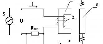
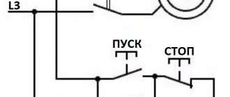
Ammeter connection diagrams
Figure - Diagram of direct connection of an ammeter
Figure - Scheme of indirect connection of an ammeter through a shunt and a current transformer
Scope of application of ammeters
Instruments for measuring current have found application in various fields. They are actively used in large enterprises associated with the generation and distribution of electrical and thermal energy.
Where are ammeters used:
electrical engineering - energy
automotive industry
exact sciences
construction
electrical laboratories
But not only medium and large enterprises use this device: they are also in demand among ordinary people. Almost any experienced auto electrician has a similar device in his arsenal, which allows him to measure the power consumption of devices, car components, etc.
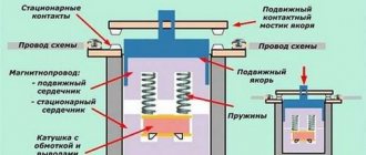
Principle of operation
The ammeter shows measurements after connecting to an electrical circuit. A current passes through it, the strength of which is recorded due to the influence of a magnetic field. If we talk about the classic, magnetoelectric version of the device, it works like this:
- The spool and pointer are attached to the axis. A magnet is installed above the coil, which creates a magnetic field and sets the initial position of the arrow - 90 degrees relative to the axis.
- If you connect the device to the network, a second magnetic field will appear, coming from electricity. The fields will “compete” with each other, pulling the arrow towards them. The potential difference of the magnetic fields determines which division the needle will eventually stop at.
You may be interested in this Features of the SIP piercing clamp
Operating principle
However, the principle of operation may vary depending on the design of the ammeter.
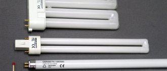
Types of ammeters
Based on the type of reading device, ammeters are divided into devices with:
- with pointer indicator
- with light indicator;
- with a writing device;
- electronic devices.
According to the principle of operation, ammeters are divided
- Electromagnetic – designed for use in direct and alternating current circuits. Typically used in conventional AC electrical installations with a frequency of 50 Hz.
- Magnetoelectric - designed to record the current strength of low values of direct current. They have a magnetoelectric measuring device and a scale with graduated divisions.
- Thermoelectric The devices are designed to measure current in high-frequency circuits. Such devices include a magnetoelectric mechanism made in the form of a conductor to which a thermocouple is welded.
Vasiliev Dmitry PetrovichProfessor of Electrical Engineering, St. Petersburg State Polytechnic University
Ask a Question
The current flowing through the wiring causes it to heat up, which is detected by a thermocouple. The resulting radiation causes the frame to deflect by an angle that is proportional to the current strength.
- Ferrodynamic devices - consist of a closed magnetic circuit made of ferromagnetic material, a core and a fixed coil. They are characterized by high measurement accuracy, reliable design and low sensitivity to the effects of electromagnetic fields.
- Electrodynamic devices are designed for measuring current in DC/AC circuits of high frequencies (up to 200 Hz). They are sensitive to overloads and external electromagnetic fields. But due to the high accuracy of measurements, they are used as control devices for checking existing ammeters.
- Digital ammeters are a modern model of devices that combine the advantages of analog instruments. Today, such devices have gained leading positions. This is due to ease of use, ease of use, small size and high accuracy of the measurement results obtained.
Abrahamyan Evgeniy Pavlovich
Associate Professor, Department of Electrical Engineering, St. Petersburg State Polytechnic University
Ask a Question
In addition, digital devices can be used in a variety of conditions: it is not afraid of shaking, vibration, etc.
Let's look at several ammeters from different manufacturers and different types:
Ammeters Am-2 DigiTOP
Specifications:
- Number of inputs 1
- Measured alternating current 1...50 A
- Measurement error 1%
- Indication resolution 0.1 A
- supply voltage -100…-400 V, 50 (+1) Hz Overall dimensions 90x51x64 mm
Orlov Anatoly Vladimirovich
Head of the Relay Protection and Automation Service of Novgorod Electric Networks
Ask a Question
The performance and durability of household electrical appliances depend on the quality of the electricity received. As a rule, failure of electronic equipment, be it refrigerators, televisions or washing machines, is caused by an increase in voltage above permissible limits. The most dangerous thing is a prolonged increase in voltage above the permissible level. In this case, power supplies for electronic equipment fail, the windings of electric motors overheat, and fire often occurs.
Laboratory ammeter E537
This device (ammeter E537) is intended for accurate measurement of current in AC and DC circuits.
Accuracy class 0.5.
Measuring ranges 0.5 / 1 A;
Weight 1.2 kg.
Technical characteristics of ammeter E537
- Measuring range end value 0.5 A/1 A
- Accuracy class 0.5
- Normal frequency range (Hz) 45 - 100 Hz
- Operating frequency range (Hz) 100 - 1500 Hz
- Overall dimensions 140 x 195 x 105 mm
Ammeter CA3020
The basic model digital ammeter device is available in several standard modifications depending on the basic value of the measured current parameters. When ordering this model of digital ammeter, you must state what basic current parameter you will have to work with: 1 A, 2 A or 5 A.
Basic parameters of the measured current, In-1 Ampere (CA3020-1), 2 Ampere (CA3020-2) or 5 Ampere (CA3020-5);
- The limits of measured currents are from 0.01 In to 1.5 In;
- Frequency range for measured currents from 45 to 850 Hertz;
- The limits of the basic permissible existing error are ±0.2% of the optimal value of the parameters of the measured current strength;
- Power supply voltage - alternating current network with voltage (85-260) Volts and frequency (47-65) Hertz or constant voltage (120 - 300) Volts;
- The power consumption of the device is no more than 4 VA;
- Dimensions 144x72x190 mm;
- Weight no more than 0.55 kg;
- The power consumed by the measuring circuit of series 3020 ammeters does not exceed: for CA3020-1 – 0.12 VA; for CA3020-2 – 0.25 VA; for CA3020-5 – 0.6 VA.
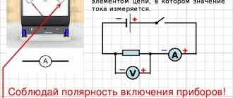
How to measure current in an electrical circuit
To measure current, a measuring device called an Ammeter
. Current strength has to be measured much less often than voltage or resistance, but, nevertheless, if you need to determine the power consumption of an electrical appliance, then without knowing the amount of current it consumes, the power cannot be determined.
Current, like voltage, can be constant or variable, and different measuring instruments are required to measure their values. Current is designated by the letter I
, and to the number, to make it clear that this is the current value, the letter
A
. For example, I=5 A means that the current in the measured circuit is 5 Amps.
On measuring instruments for measuring alternating current, the letter A is preceded by the sign “
", and those intended for measuring direct current are marked "–
".
For example, –A
means that the device is designed to measure direct current.
You can read about what current is and the laws of its flow in a popular form in the website article “The Law of Current Strength”. Before taking measurements, I strongly recommend that you read this short article. The photo shows an Ammeter designed to measure direct current up to 3 Amperes.