Types of connectors
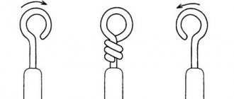
Connectors that provide connections to electrical circuits come in different types, much depending on their size:
- Micro-jack 2.5 mm is used in miniature devices: smartphones, tablets, etc.
- Mini-jack 3.5 mm are designed for a wide variety of household appliances, including desktops and TV receivers.
- Big-jack 6.35 mm is a connector that is necessary for acoustic devices: amplifiers, guitars, mixers, etc.
Each of them has several subspecies depending on the number of outputs:
- With two contacts, asymmetrical pulses are transmitted. Example: mono impulses for headphones, recording on a microphone.
- If there are 3 contacts, then it is permissible to transmit symmetrical and asymmetrical pulses. Connections No. 2 and No. 3 are fixed to each other using an additional adapter.
- The 4-pin jack allows you to broadcast video and audio impulses in one package. The elements are used in smartphones, tablets, and audio devices.
- The 5-position unit is an outdated format, it was developed by Sony for the Xperia Z series phones. In this case, 2 microphones function, 1 controls noise reduction. The sockets also have 2 types: standard, created for special blocks, and switchable (can be adjusted to any connection).
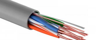
If the block has 3 outputs, it is called TRS. The cable includes 3 cores.
There are combinations - 2 pairs, one wire from a pair of one color is taken as a common one, and connected together.
Standard
In the simplest wiring, the right channel is attached to the middle ring, the left - to the connecting block. The cores are fixed in the appropriate places intended for soldering - they are easy to detect upon closer inspection or check with a tester.
Product 2.5 is made on the same principle as 3.5, the only differences are in size. The wiring on both types is the same. In mobile phones, headphones and microphones are fixed using mini- and micro-USB connectors. They can be used while listening to MP3 files.
Non-standard
There are devices where the input to the headset is different. For example, in phones from various companies:
- Nokia;
- Samsung;
- Ericsson.
In headsets with a button, a USB connector is sometimes installed; when repairing such devices, difficulties arise due to the non-standard plug. Then you need to connect a standard headset through the appropriate adapter.
How to Determine Headphone Jack Size
Most users can determine the diameter of a connector or plug visually, since the vast majority of devices are equipped with a 3.5 mm jack. If the diameter of the plug in your device is smaller than usual, then it is a 2.5 mm jack; if you are using professional equipment or a musical instrument with a connector of increased diameter, it is probably a 6.35 mm connector. It will not be difficult to distinguish a jack from Lightning and US.
Inexperienced users should use a measuring device, such as a caliper, although a school ruler will show a difference of 1 mm.
Pinout diagrams for headset with microphone
The pinout varies, much depends on the headphones. Blocks have from 2 to 4 elements, each part transmits its own signal. For example, the connection block has 2 elements; it is equipped with one wire, which is intended for a microphone.
If there are 3 elements, then there are 3 wires:
- right;
- left;
- general.
In the headset, the 1st channel is connected to the right earphone, the 2nd channel to the left, the common one supervises the fixation of contacts.
A cable is pulled to the plug; in the center it is divided into 2 wires, each going to its own earphone. The block has 4 elements. In this combination, it is differentiated into 2 types. The 1st block consists of 4 wires (most often this happens in phones, tablets, players). The channels are divided into left, right, general and microphone.
All modern modifications of phones are equipped with plugs in which there are 4 elements (fixed with headphones and a microphone).
The pinout is done according to the same scheme for the following devices:
- "Apple";
- "Samsung";
- "Lenovo".
If you analyze the connecting block, it is composed of several elements. Each of them supplies impulse to its own channel.
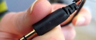
So, let's go fix the headset jack
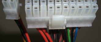
First, let's look at the headset jack itself. It's called 4-pin Jack 3.5mm , but somehow it doesn't make any difference. So, it has 4 contacts, and each contact has its own purpose. There are two standards for pin layout:
In this piece of art I tried to depict the purpose of the pins. M- and M+ are microphone contacts. The other three are the headphone contacts already familiar to you from the first article : G - ground, R - right, L - left. The colors with which the contacts are painted are not random; these are standard colors that are most often used by manufacturers to distinguish wires.
Now the first option has almost completely died out. And this is not due to the fact that the second traffic lights on the contacts are more correct and not even with the Rastafarian tricolor, but with problems of compatibility with 3-pin connectors of laptops, players... I think everyone has come across headphones that play normally from a laptop only when they are not inserted all the way. This is the first option.
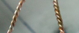
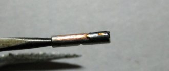
But let's return to the colors of the headset wiring. In order not to be unfounded, here is a cut cable from a Beats Tour headset. Classic wire color scheme:
But alas, everything is not always so good and the manufacturer does not always make our life so easy. It is not possible to consider absolutely all color scheme options. And it doesn’t make sense, it’s better to understand how to determine which wiring is responsible for what in any circuit. This is what we will do 
Headphone wiring
For standard headphones to work, 3 wires are needed, counting from the sharp end to the cable. Some models have 4 elements, divided into pairs. Wires of the same colors are soldered together. Removing them with a jack connection is easy. The elements are attached to the intended places, which are found using a tester. Jack 2.5 differs only at the connector point, but the algorithm is the same. Micro and mini-USB are available in mobile devices; they are fixed congruently.
Necessary equipment
Tools required for desoldering:
- medium power soldering iron (up to 25 W);
- solder;
- rosin;
- multimeter;
- pliers;
- blade;
- manicure scissors;
- sharp knife;
- small screwdriver;
- emery cloth.
At the beginning of work, the connector is tested; it must match the one that is being dismantled.
Other examples of headset jack wiring
Here, without looking or checking, you can solder two gold wires together
It's just that each channel has its own wire for ground. From an audiophile point of view, this option is more correct than one ground wire and contributes to a wider stereo base.
In general, it turns out that the whole problem of repairing the headset connector comes down to determining where the ground is that needs to be twisted to get 4 wires.
I repeat once again - the earth is always yellow. Also, mixtures of yellow with other colors are usually also earth.
Important points before unwiring headphones
The reason why headphones with a microphone do not work may also be the incompatibility of two headsets: a telephone and headphones. It is for such situations that special adapters have been developed. So if there is a problem with hearing in headphones, then first you need to check the most obvious options.
Before you begin repairing your headphones, you need to determine the cause of the problem. Quite often, wire rupture occurs in the place where the wire is constantly subject to twisting, namely in the plug. Less commonly, damage may occur in the cable. In this case, you should simply completely change it to another one. To determine that there is no sound from the speaker due to a fault in the plug, you can try pressing the cable into the base of the connector, twisting it in different directions. If sound appears after this, then this is where the problem lies.
In order to start wiring a headset with a microphone and a button, you should study the types of connectors. There are cables with three wires, four, five and even six. Headphones with a microphone are connected via 4 wires. Some models are equipped with non-standard connectors.
Note! If, when wiring headphones, the new connector is of a non-standard type, then the connection requires the use of an appropriate adapter device.
Headphone repair
If you have minimal skills in working with a soldering iron and a tester, broken wires can be repaired.
Troubleshooting
In working headphones, the sound should be clear, without crackling or loss of sound, and the voice of the speaker at the other end of the line should also be without crackling or interruptions. If this is not the case, then there are two possibilities: a malfunction of the device or headphones. To check, the headphone plug should be connected to a known working device:
- problems remain - a malfunction in the headphones;
- the problems are gone - the device is faulty.
You can do the opposite: connect known-good headphones to the device:
- the problems are gone - the stereo headphones are faulty;
- The problems remain - the device is faulty.
In most cases, the reason is broken wires to the plug or “rocker” (volume control buttons) or to the speaker. The earphone or rocker should be disassembled and the wires soldered, and the plug should be changed or repaired.
Before soldering the wires going to the plug, determine the location of the break. This is done with a tester or multimeter turned on to check resistance:
- connect the tester to the plug; bend the wire, following the tester readings;
- when the cable bends at the break point at the plug, the device readings will change;
- If the break is permanent, then there may be a malfunction or break near the earphone.
Continuity of wires
If the cable inside the plug breaks or it is impossible to remove the protective sheath from it, it is necessary to determine whether the wires match the speakers, microphone and control panel. In this case, different connection schemes are possible:
- the microphone and the rocker are connected using one pair of wires or different ones;
- sometimes the microphone is connected with a shielded wire;
- There is one common wire for all elements or one for each part.
First of all, before soldering the headphone wires, you need to find the ends going to the speakers. This is done with a tester or multimeter turned on to measure resistance:
- strip the wires to 10 mm of insulation; if there is a shielded wire among them, then it goes to the microphone;
- put on headphones and start ringing the wires one by one;
- when connecting the tester to one of the channels and the common conductor, a crackling sound is heard in one of the phones;
- to the left and right channel - in both.
If the headphones do not have a microphone, then the cable is soldered to the plug, and in the headset, after dialing the speakers, the wires going to the microphone and buttons are determined:
- 4 wires. The remaining one is connected to the microphone;
- 5 cores The remaining two are connected to each other and do not communicate with the speaker - they are connected to a microphone and soldered to the common terminal and the microphone terminal. If they are ringing with stereo headphones, then this is the control panel, and the microphone and both wires are connected to the microphone output;
- 7 cores These are two pairs - to the microphone and to the buttons. Soldered by color in parallel to the common and microphone terminals.
How to solder headphones to a plug
The plug is made of soft plastic, and the pin with slip rings is poured into it. To repair, the case will have to be cut and then connected using heat-shrink tubing of a suitable diameter.
A break in the wire going to the plug can be repaired by soldering:
- cut the cable;
- carefully cut the sealed plastic case and remove the plug itself from it;
- remove cable residues from the housing using a thin drill;
- the cable going to the headphones is stripped to the length required for soldering;
- use a tester to check the functionality of the headphones;
- tin the ends of the cores by 5 mm;
- put the notched housing through the previously drilled hole onto the cable;
- solder the wires to the metal middle of the plug, according to the colors of the insulation or the results of ringing;
- the middle with a soldered cable is placed in a plastic case;
- A piece of heat-shrinkable tubing is put on top and heated with a hairdryer.
The plug on the headphones is also replaced.
Advice. It is better to take the heat-shrink tube in the same color as the wire.
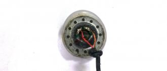
Headphone speaker repair
If there is no sound from one of the speakers, the reason may be a broken wire connecting to it. To repair a faulty earphone, you must open it. In large models, the cover is attached with screws, and in small ones - with latches or with glue. Such speakers are opened with a knife inserted into the gap between the covers.
The soldered wire must be secured inside. To do this, a knot is tied on it, or it is glued with superglue.
The disassembled speaker is assembled and, if necessary, the covers are glued to each other.
Knowing how to replace the wire and how to change the plug will help you save on purchasing new stereo headphones, and in order to solder the plug to the headphones, you need to know the pinout of the wires.
What is needed for desoldering
To pin out a faulty headset, you must prepare the following:
- New connector for replacement. It should be the same type as the old one.
- For high-quality soldering you need a soldering iron. Its power should not be high - 25 watts.
- Rosin and solder.
Today, there are ways to connect a cable without resorting to soldering elements. However, the procedure carried out using a soldering iron guarantees better quality work. Soldered contacts are more durable and will last a long time.
![Turboloan [CPS] RU March](https://dush-pol.ru/wp-content/uploads/turbozajm-cps-ru-mart-330x140.jpg)