02/17/2015 computer repair
Whether you decide to assemble the computer yourself or just the USB ports, the headphone output on the front panel of the computer system unit does not work - you will need information on how exactly the connectors on the front panel are connected to the motherboard, which will be shown below.
We will talk not only about how to connect the front USB port or get headphones and a microphone connected to the front panel to work, but also about how to connect the main elements of the system unit (the power button and indicator, the hard drive indicator) with the motherboard and do it right (that's where we'll start).
Micro USB connector pinout
First, let's give the wiring for this specification:
As can be seen from the figure, this is a 5 pin connection. Both the plug (A) and socket (B) have four contacts. Their purpose, numerical and color designation corresponds to the accepted standard, which was given above.
Description of the micro USB 3.0 connector
For this connection, a characteristically shaped 10 pin connector is used. In fact, it consists of two parts of 5 pin each, and one of them fully corresponds to the previous version of the interface
This implementation is somewhat confusing, especially considering the incompatibility of these types. Probably, the developers planned to make it possible to work with connectors of earlier modifications, but subsequently abandoned this idea or have not yet implemented it
The figure shows the pinout of the plug (A) and the appearance of the micro USB socket (B). Contacts 1 to 5 are fully consistent with the second generation micro connector. The purpose of other contacts is as follows:
- 6 and 7 - data transmission via high-speed protocol (SS_TX- and SS_TX+, respectively).
- 8 - mass for high-speed information channels.
- 9 and 10 — data reception via high-speed protocol (SS_RX- and SS_RX+, respectively).
Advantages
The USB cable with micro plug is distinguished by its increased strength and reliability of the case. In case of improper handling and repair, the contacts may break. Malfunctions are caused by sudden movements when connecting to the port, or by falling of the gadget, especially when the connector hits a hard surface. Sometimes malfunctions occur due to manufacturing defects or improper use.
USB Micro Cable
If soldering is done incorrectly when connecting the cable, failures occur, which are characterized by the following symptoms:
- notifications about hardware errors appear on the gadget’s screen, the device does not find or does not recognize the connection;
- there is no synchronization between connected devices, but charging is carried out;
- The battery icon identifies the charging process, but no actual power is supplied;
- the device does not respond to connection or issues a failure alert;
- There is a short circuit in the power supply or port.
Poor contact may be caused by irregularities that occur between the chain links. Soldering is carried out using pin desoldering. This procedure is called pinout. Each wire is reconnected after stripping, based on color identification.
Functions of the “legs” of the micro-USB connector
The micro-USB connector is used to charge small and portable volatile devices and synchronize data between PCs and gadgets. It consists of five "legs". Two “legs” are separated on opposite sides of the case: one is the positive 5V rating, the second is the negative one. This arrangement reduces the likelihood of breakdown.
Close to the negative leg there is another contact, which can easily break if connected to the port carelessly. If this “leg” is damaged, the cable fails
The battery icon may indicate connection progress, but may not actually charge. Most often, this damage results in the gadget not responding to the plug being connected.
The two remaining “legs” are used for data exchange and synchronization between devices. With their help, you can upload and download files from the gadget to your PC and back, transfer videos, photos, and audio. The work is carried out synchronously. If only one contact is damaged, the second one stops working. Knowing the color pinout allows you to solder the wires correctly and resume the plug’s operation.
Watch this video on YouTube
Pinout of USB type connectors.
- the first wire (red), it is supplied with a DC supply voltage of +5 V;
- the second contact (white), it is used to transmit information (D-);
- the third wire (green), it is also intended for transmitting information (D+);
- the fourth contact (black), zero supply voltage is supplied to it, it is also called the common wire.
- The first four pins are completely consistent with the 2.0 standard, so let's move on.
- The fifth pin (blue) is used to transmit information with a minus sign of USB3 (StdA_SSTX).
- The sixth pin is similar to the fifth pin, but with a plus sign (yellow).
- Seventh – additional grounding.
- The eighth pin (purple) is for receiving USB3 data (StdA_SSRX) with a minus sign.
- And finally, the last ninth (orange) is the same as the seventh pin, only with a plus sign.
Pinout of micro USB connector
Pinout of micro USB type:
- the first contact (red) is intended to supply + 5 V supply voltage;
- the second and third wires (white and green) are used for data transmission;
- the fourth lilac contact in type B connectors is not used, but in type A connectors it is connected to a common wire to support the OTG function
- the last, fifth, contact (black) is supply voltage zero.
Computer technology has swept the whole world and, probably, there is no person who does not know how to use a computer. But of course, people are interested not only in the computer itself, but also in all the additional elements that change, speed up and transform the operation of such computer equipment.
Thus, recently universal USB buses, which serve as a computer interface, have become very popular. They were invented in the twentieth century, but they began to be developed only three years later. And then a new USB model appeared, which, unlike the first one, worked much better. For example, the speed of its work was increased forty times. And therefore the charge lasted longer.
But after some time, the developers of such a computer interface as USB still had low speed
in order to use external hard drives and other devices whose speed was much greater. Therefore, the creators of USB had to change the device so that a new model was obtained. Now the speed of the third type of USB has become ten times faster. Of course, this also affected charging.
The USB cable consists of four conductors made of copper. These are two conductors intended for power supply, and the remaining conductors are in a twisted pair. This kit also includes a grounded braid.
USB cables have different physical ends. It depends on what device it is connected to. There are connections to the device itself and to the host. Moreover, USB can be with or without a cable. Another option is possible: the cable is built into the device itself. The cable is necessary to form an interface between the device and the host.
Let's now take a little look at the host. It acts as a special controller, which is programmed and controlled. Its task: to ensure the operation of the interface. By the way, the controller can most often be found in a microcircuit. A hub is required to connect the controller to other devices.
But in order to connect external devices to the hub, ports are used, at the end of which there are connectors. Cables help USB devices connect to ports. The device can be powered differently: from the bus or some kind of external power source.
It only takes a few minutes to get started and you can get started. First, the signal to start working is sent to the cable hub
, which further informs that the equipment is ready for operation.
But it is worth remembering one rule. Whenever you start pinouting a device, first determine what the pinout is on your cable. The USB connector helps you connect all external devices to your computer. This modern connection method replaces all those methods that were previously available. This connector provides additional options
: When operating computer equipment, any devices can be connected and immediately put into operation. It may also affect the charging operation.
Port location and markings
Modern motherboards are most often equipped with four, six or eight such ports. Typically, two or four of them are tightly soldered in such a way that they can be accessed from the rear panel - where the keyboard and mouse jacks, audio outputs and everything else are located.
Other ports are located on the “mother” itself and are connectors with protruding pins. To connect the front ports to the motherboard, special connectors are used. With their help (and also to the USB port on the motherboard), a card reader is connected, if there is one of course.
This connector is missing one socket in the lower left corner. That is, where there should be 10 holes, there are only 9 of them. Thanks to this, it is easy to understand exactly how to connect this connector to the plug on the motherboard.
To connect an external port, you need to carefully push the plug onto the connector until it stops. Try not to make sudden movements left or right, as you can break one or more pins, which will cause that port to become inoperable and you will have to use the next one.
On the motherboard, these ports are most often located near the SATA interfaces and are marked with the abbreviation USB with a serial number. There is absolutely no difference in what exactly and where to connect - the ports work in parallel.
Connecting a car recorder via DCDC and pinout the power cable
USB cable pinout diagram by color
I'm tired of having a recorder and a lot of other crap stuck in the car's cigarette lighter all the time. So a bright idea came to my mind that it was necessary to remove all the ugly wires and finally make it beautiful. Look how black and white the poop is in the area of the right visor.
I bought 2 mini USB cables twisted into a spiral (you may have others! Check), a DCDC pulse converter with a voltage regulator and a peak load of 3A (or better yet, 5A and then nothing will get hot) and some small items for convenience. Chinese DCDCs do not dissipate heat well, so I took a small heatsink for the video card chips and attached it to a pad that dissipates heat. Next, it remains to solder the USB connector and the general power connector to make it convenient to disconnect and repair
Please note that to power the recorder, the voltage must be increased to 6 volts and nothing else can be inserted there under the threat of device failure. Just in case, measure the power supply voltage of your recorder. What if it will be different from my 6 volts? If the converter will be used to charge mobile phones and tablets, then you need to set it to strictly 5 volts
Don't forget the fuse! 4A will be enough. Regular cables are not as convenient, so I bought a spiral cable with micro usb. It looks cool and will stretch if you happen to pick up the phone. Total advantages!
What if it will be different from my 6 volts? If the converter will be used to charge mobile phones and tablets, then you need to set it to strictly 5 volts. Don't forget the fuse! 4A will be enough. Regular cables are not as convenient, so I bought a spiral cable with micro usb. It looks cool and will stretch if you happen to pick up the phone. Total advantages!
Now for all this crap to work, to power the recorder, you need to modify the USB cable so that the recorder considers my power source not a computer, but an original power supply. If your recorder, when connected to such a cable, does not try to switch to computer mode, then you do not need to do anything. I gave links to cables above. They are very easy to disassemble and re-solder as needed. Use this if you don't want to assemble the cable entirely by hand.
Wiring diagram for the cable you purchased:
It needs to be modified as follows: 1 – not used 2 – not used 3 – not used 4 – (not indicated by a number in the picture) (+6V). 5 – (in the picture as No. 4) (-) mass.
Those. Basically, you just need to transfer the power wire (red) from one contact to another, and just cut off the rest. Observe polarity! In the picture above, the sockets (female) are shown on the left, and the plugs (male) are shown on the right. Don't overheat the wires! The insulation on them melts very easily! Check the cable for a short circuit with a tester and insulate the soldered wire with heat shrink. During operation, the wire I soldered came off and shorted with another. As a result, the DCDC converter burned out. Now I not only insulated the wires, but also filled the entire connector with a compound to prevent vibration.
If during disassembly you accidentally damaged 1 of the 4 locks, you can simply solder the connector as in the photo above. I only broke 1, but decided to play it safe. You never know what will happen on the road. There is no need to modify the cable for your tablet or phone!
In the end, I ended up with this assembly. The second photo shows a new DCDC with a fuse and a voltmeter/amperemeter.
The power source will be placed in my cavity above the walkie-talkie and 2 wires will come out of it on the sides to power the recorder and power the tablet.
If the tablet consumes more than 1A while charging, then buy a more powerful DCDC. Just in case, I ordered a separate 5A DCDC from DX, which I will install later next to the first one.
If you are passionate about talking on the radio with other people, then read my articles about the Baofeng UV-5RA wearable VHF radio and about installing a Megajet radio in the interior of a restyled Niva Chevrolet. I have already exchanged the Megajet MJ-350 for the MJ-600+ turbo and they are no different in the design of the holder.
The USB interface is a popular form of technological communication on mobile and other digital devices. Connectors of this kind are often found on personal computers of various configurations, peripheral computer systems, cell phones, etc.
A feature of the traditional interface is the USB pinout of a small area. For operation, only 4 pins (contacts) + 1 ground shield line are used. True, the latest more advanced modifications (USB 3.0 Powered-B or Type-C) are characterized by an increase in the number of working contacts. This is what we will talk about in this material. We will also describe the structure of the interface and the features of cable wiring on the connector contacts.
Pinout of the main power cable connector
Connector pinout of ethernet connector cable connection diagram
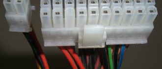
The pinout of a computer's power supply starts with the largest and most important power cable - this is the cable connected to the motherboard. On old-style motherboards, the ATX connector is designed for 20 pins, while new generation motherboards already contain 24 pins in their connector. It is for this reason that new generation power supplies have cables with a 20+4 pin plug.
When pinouting a computer's power supply, it is important to know that the ATX plug is only suitable for powering the motherboard. This can be checked by looking closely at the contacts in the plug and connector - each of them is unique and suitable for only one purpose
Connecting the system unit to the Internet
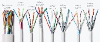
To connect your computer to the Internet, you need to use the network port on the motherboard.
Connect the Internet cable (twisted pair) or patch cord to the router, and its second connector to the RJ-45 connector on the motherboard. When you turn on your computer, the router will assign an IP address to your PC, and the operating system will automatically configure the built-in network card on the motherboard.
That's it, after connecting external devices to the system unit, you can turn on the computer. Don't forget to turn on the power supply.
Characteristics
Reviews
Discounts
Go to the Market section
Product not found! Reset the filter or refine your query.
How to connect wires to a computer
*Video may differ from the topic of the article
How to connect usb to the motherboard. Connecting additional USB ports on your computer
USB is one of the most popular interfaces, used in the vast majority of devices. Almost any equipment is connected through it - from a regular mouse to a smartphone or gamepad. The problem is that sometimes there are so many devices that there are not enough connectors to connect them.
If nothing can be done with the laptop (the only option is to purchase a special adapter), then there is always the opportunity to install a couple of additional ports in the computer system unit. Let's see how to connect USB to a computer.
USB cable wiring by color
The pinout of the USB connector differs in that the interface cables of version 2 use four wires (mini and micro versions - 5 wires), while in version 3 the number of wires is increased to nine.
Wiring the USB connector is made easier by the fact that the wires of the standard cable are assigned specific colors, shown in the table below.
| Wire number | USB2 | USB3 |
| 1 | red (plus power) | red (plus power) |
| 2 | white (data) | white (data) |
| 3 | green (data) | green (data) |
| 4 | black (zero power or common) | black (zero power or common) |
| 5 | — | blue (USB3 – transfer) |
| 6 | — | yellow (USB3 – transfer) |
| 7 | — | Earth |
| 8 | — | purple (USB3-receive) |
| 9 | — | orange (USB3 – reception) |
The fifth wire in mini and micro connectors of type B is not used, but in connectors of type A it is shorted to the GND wire.
The screen drain wire (if present) is not assigned a separate number.
A summary of the distribution of wires of USB interfaces version 2 across the pins of various types of plugs is shown in the figure below.
USB cable wiring by color
How to connect a USB cable to a computer?
A USB port is by far the most common type of connecting devices to a computer or laptop. There are three types of connectors: 1.0, 2.0 and 3.0. If the first one can now be found only on the oldest computers, then the second and third ones are used today. At their core, they differ in data transfer speed
And in appearance, what is more important for us now is color. USB 2.0 has a black connector and plug, USB 3.0 has a blue color
You can read more about the specifications and differences between standards here.
Before connecting the USB cable to the computer, look at the plug of your gadget - if the blue connector is connected to the black port, the device will not use all its speed characteristics to the maximum. If you plug the black plug into the blue one, then absolutely nothing will happen - the USB 3.0 port will simply operate at the speed that is maximum for 2.0.
So, look at the back panel of your computer, find a USB port of the same color as the plug, and connect it.
After this, the device will either be detected by itself in the system, if it is a keyboard, mouse, webcam, or some other simple and common device for which Windows already has a driver. Or to work you will need to install the software that comes with the device on CD.
Tsokolevka
The layout of the USB connector depends on the specification of this interface of its types
They are visually different and in order not to confuse them when connecting to equipment, pay attention to the following: A – for a computer or hub; B – for a peripheral device. The first versions of connectors (up to USB2.0) were physically no different from each other and had four contacts: 1.4 – for supplying plus (+5 V) and minus (Gnd) supply voltage; 2.3 – for differential data transmission
For clarity, we present their images and pinouts in the figure.
USB3.0 also has two types of connectors A and B. Both are equipped with nine pins, while the first four are fully backward compatible with version 2.0 discussed above. Five additional contacts have the following purposes: 5-6 receive (RX), 8-9 transmit (TX) data; 7 – additional signal grounding (Gnd-Drain).
The wires of the USB cable have different colors, in the pictures above you can see which color is used for transmitting signals and which for power. All types of USB have additional modifications for use in portable mobile devices. These miniature connectors are designated by the words “mini” or “micro”. We encounter them everywhere in everyday life and use them to recharge cell phones and other mobile gadgets.
Charger port classification
- SDP (Standard Downstream Ports) – data exchange and charging, allows current up to 0.5 A.
- CDP (Charging Downstream Ports) – data exchange and charging, allows current up to 1.5 A; hardware identification of the port type (enumeration) is performed before the gadget connects the data lines (D- and D+) to its USB transceiver.
- DCP (Dedicated Charging Ports) - charging only, allows current up to 1.5 A.
- ACA (Accessory Charger Adapter) - PD-OTG operation in Host mode is declared (with connection to PD peripherals - USB-Hub, mouse, keyboard, HDD and with the possibility of additional power supply), for some devices - with the ability to charge PD during OTG- sessions.
Connecting the front panel to the motherboard
First of all, I recommend opening the user manual and looking for the wiring diagram there. If you don’t have a paper copy, you can find it in electronic form on the manufacturer’s official website (as a rule, at the top of the site go to the “Products” tab, find the motherboard category there and from there look for your model).
I am attaching links to official sites:
- Asus
- Gigabyte
- MSI
- Asrock
Also, on the PCB of the board itself, tips are most often written to help with connection. The example below is an excellent indicator of the correct tips in order to figure out how to connect the front panel to the motherboard.
Let's take a popular and current motherboard as an example and look at the connection connectors on them.
Let's get started
First of all, let's look at the Gigabyte B450M DS3H motherboard model with an AM4 socket for connecting processors from AMD. This motherboard is quite popular for low-cost Ryzen builds, which means the example will be relevant.
The most common place to place front panel connection pins is the very bottom of the board. Let's look at the connection on this board.
- USB 2.0 (there are two connectors on the board. If there is only one cord, then connect to any of them)
- USB 3.0
- Power Led
- HDD Led
- Power SW
- Reset SW
- CI (case intrusion sensor, not as common as the others)
- Speaker
The most attentive of you may have already noticed the absence of an HD Audio connector, but don’t worry. It's just located in a different part of the board, namely on the left.
The official documentation tells us the same thing that I told you.
Now, for comparison, let’s take a similar, but slightly cheaper board from the same company - Gigabyte B450M S2H.
This board has fewer RAM slots and connection connectors and, in principle, is intended for a slightly cheaper segment. The pins here are located closer to the middle, let's look at them in more detail.
- HD Audio
- USB 2.0 (there are two connectors on the board. If there is only one cord, then connect to any of them)
- Speaker
- Power Led
- Power SW
- HDD Led
- Reset SW
- USB 3.0
Note that this model does not have the CI (case intrusion) connector that was present in the previous example. This is not a big problem since it, as mentioned, is not very common.
In the official documentation we can see this diagram.
Now it will be much easier for you to navigate the system documentation when you have seen this in an example, right?
Absolutely the same designations on the PCB of the board and the diagrams in the user manual will look almost the same whether it is a Chinese Killsre X79 board for Intel Xeon on LGA2011, or an old MSI N1996 K9N for AMD on AM2.
Connecting USB ports on the front panel
In order to connect the front USB ports (as well as a card reader if available), all you need to do is find the corresponding connectors on the motherboard (there may be several of them), which look like the photo below and plug the corresponding connectors into them , coming from the front panel of the system unit. You can't go wrong: the contacts here and there correspond to each other, and the connectors are usually labeled.
Usually, there is no difference in where exactly you connect the front connector. But for some motherboards it exists: since they can be with or without USB 3.0 support (read the instructions for the motherboard or carefully read the labels).
Benefits of use
USB connector (Universal Serial Bus) is a technology by which a peripheral device is connected to a PC or Mac. A USB connector is a convenient way to wire a gadget to a computer. Let's take a closer look at what USB is.
Advantages of using a serial universal bus.
- Prevalence. Each PC has on average 2-4 such inputs, which allows you to connect several devices at once. This prevalence has been observed for a long time.
- Easy to use. The user does not have to worry about drivers; no effort is required. The operating system automatically connects the necessary drivers to “see” the peripheral device. The user just needs to connect the USB cable, and the computer will do the rest.
- High throughput. This allows you to exchange files at good speed. There is no need to wait 2-3 hours for the selected file to be saved to your computer. This operation takes from 5-10 seconds to 10 minutes (depending on the size of the document). The exact speed depends on the type of USB.
- Charger. In addition to the basic viewing and transmission functions, an additional one is available - recharging. When you connect your phone to your computer via USB, the device starts charging automatically. The speed at which power is received through the computer is less than the speed at which power is supplied through the charger. And there is not always an outlet at hand.
The technology helps the user connect with the computer in minimal time. It’s convenient to plug the cable into the USB output and get started.
Types of USB connectors
The abbreviation “USB” carries an abbreviated designation, which in its entirety reads as “Universal Series Bus” - a universal serial bus, thanks to the use of which high-speed digital data exchange is carried out. The versatility of the USB interface is noted:
- low power consumption;
- unification of cables and connectors;
- simple logging of data exchange;
- high level of functionality;
- Wide support for drivers for various devices.
What is the structure of the USB interface, and what types of USB technology connectors exist in the modern world of electronics? Let's try to figure it out.
USB connector pinout - arrangement of wires by color in relation to the connector contacts. Incorrect wiring will lead to failure of the connected gadgets.
USB connector pinout
Technological structure of the USB 2.0 interface
Connectors related to products included in the specification group 1.x - 2.0 (created before 2001) are connected to a four-core electrical cable, where two conductors are power and two more are transmitting data. Also, in specifications 1.x - 2.0, wiring of service USB connectors requires the connection of a shielding braid - in fact, a fifth conductor. Existing versions of universal serial bus connectors of the noted specifications are presented in three options:
- Normal – type “A” and “B”.
- Mini-type “A” and “B”.
- Micro – type “A” and “B”.
The difference between all three types of products lies in the design approach. If normal connectors are intended for use on stationary equipment, “mini” and “micro” connectors are made for use in mobile devices. Therefore, the last two types are characterized by a miniature design and a slightly modified connector shape.
Pinout table for standard type “A” and “B” connectors
| Contact | Specification | Cable conductor | Function |
| 1 | Power + | Red (orange) | + 5V |
| 2 | Data - | White (gold) | Data – |
| 3 | Data + | Green | Data + |
| 4 | Nutrition - | Black blue) | Earth |
Along with the execution of connectors of the “mini-A” and “mini-B” types, as well as connectors of the “micro-A” and “micro-B” types, there are modifications of the “mini-AB” and “micro-AB” type connectors. A distinctive feature of such designs is the wiring of the USB conductors on a 10-pin pad. However, in practice, such connectors are rarely used.
Micro USB and Mini USB interface pinout table for type “A” and “B” connectors
| Contact | Specification | Cable conductor | Function |
| 1 | Power + | Red | + 5V |
| 2 | Data - | White | Data – |
| 3 | Data + | Green | Data + |
| 4 | Identifier | – | Host - device |
| 5 | Nutrition - | Black | Earth |
Technological structure of USB 3.x interfaces
Meanwhile, the improvement of digital equipment had already led to the obsolescence of specifications 1.x - 2.0 by the time of 2008. These types of interfaces did not allow the connection of new equipment, for example, external hard drives, in such a way that a higher (more than 480 Mbit/s) data transfer rate was provided.
Accordingly, a completely different interface was born, marked with specification 3.0. The development of the new specification is characterized not only by increased speed, but also by increased current - 900 mA versus 500 mA for USB 2/0. It is clear that the appearance of such connectors has made it possible to service a larger number of devices, some of which can be powered directly from the universal serial bus interface.
What USB looks like
USB pinout on the motherboard: what, where and how
Most modern peripheral devices are connected via a universal serial bus. Therefore, the USB pinout on the motherboard plays a very important role in the operation of a modern computer. There are two ways to install these connectors. The first is mounting directly on the board. At the same time, it is displayed on the back side and is immediately ready for use. But it’s not always convenient to connect to it, so we developed another method. Its essence lies in a prepared footprint on the main PC board, to which wires from the front panel are connected. And the connector is located on it.
One USB 2.0 universal serial port has 4 pins. The first of them is designated “+5V”. It provides power to the peripheral device. The second and third are contacts through which information is transmitted. They are designated “DATA-” (minus data transfer) and “DATA+” (plus data transfer), respectively. The last one, the 4th one, which includes the USB pinout on the motherboard, is “GND” - ground supply. In accordance with today's standards, they are designated by the following colors: power - red, "DATA-" - white, "DATA+" - green, and "GND" - black.
Such interface connections are made in pairs, so the board has 2 USB standard connectors on one contact group. The wiring consists of 9 contacts: 4 to one connector, 4 to another, and the last two play the role of a so-called key. There is a pin installed in one place, but not in another. This is done so that it is impossible to confuse them and to make the connection correctly. The fitting from the front panel is made in a similar way. Therefore, when connecting, the first to the second should be installed without problems. If this does not happen, then you need to see if you are doing everything correctly.
Recently, version 3 of the USB standard has become increasingly popular. The pinout on the motherboard is significantly different, since significantly more wires are used to transmit information. There are only 9 of them in this design. In addition to the previously mentioned 4, 2 pairs of “Superspeed” + and 2 pairs of the same type, but only with a minus, are added, as well as “GND Drain” - additional ground. It is the larger number of wires that allows you to increase the data transfer speed. Their wires are designated blue by color, purple for minus, yellow, orange for plus, and another black for additional grounding. As the number of wires increases, the USB pinout on the motherboard increases in direct proportion. For this standard, 19 contacts are already used. One of them is a key, and its purpose is to ensure that the connection is correct.
Using the universal serial bus, a great variety of devices are connected to modern computers and laptops. A printer, scanner, MFP, flash drives, keyboard, mouse and other devices that significantly expand the capabilities of a PC - all of this is connected to the computer via this interface. It is not always convenient to connect to the back of the computer, and the number of integrated connectors may not be enough. It is to solve this problem that the USB pinout was made on the motherboard, which allows you to significantly increase the number of ports.
Connecting additional USB ports on your computer
USB is one of the most popular interfaces, used in the vast majority of devices. Almost any equipment is connected through it - from a regular mouse to a smartphone or gamepad. The problem is that sometimes there are so many devices that there are not enough connectors to connect them.
If nothing can be done with the laptop (the only option is to purchase a special adapter), then there is always the opportunity to install a couple of additional ports in the computer system unit. Let's see how to connect USB to a computer.
Connecting the front ports
Almost all modern system units are equipped with several USB connectors, which are located not on the back, but on the front panel. However, they usually do not work because they are not connected to the mother card.
Attention! All work is carried out with the computer turned off from the network. Turn off the computer and remove the side cover. Locate the wires that come from the front of the system unit
They can be a coiled bundle of several thin cables or a solid wire.
Turn off the computer and remove the side cover. Locate the wires that come from the front of the system unit. They can be a coiled bundle of several thin cables or a solid wire.
Look carefully at the motherboard - there should be a connector on it, next to which it says USB (usually it is blue). Install the wire from the front ports into the motherboard connector. Assemble the system unit and turn on the computer. Now the front ports should work: you can, for example, connect Lenovo to a computer using them.
Installation of additional equipment
Do you want to connect a gamepad to your computer, but all the connectors, including the front ones, are occupied by other devices? Then you will have to purchase a USB controller that is installed in the PCI slot on the motherboard. If you connected a video card, you can easily install another card if there is a free slot.
If there are no free slots left on the motherboard, use external USB hubs.
Such devices are connected to an existing connector and allow you to seriously increase the number of ports. By installing several controllers and adding a number of hubs, you can increase the number of working USB ports to 127 (this is a protocol limitation; it simply won’t work anymore). Of course, the average user is unlikely to need such a number, but a couple of ports will never be superfluous.
https://youtube.com/watch?v=S0UD5f3dgtk
Connecting the front panel of the computer to the motherboard
Published: June 5, 2015. Author: Igor
If you decide to assemble or disassemble a computer, this article will be very relevant for you. It will discuss how to properly connect the panel of front buttons and USB ports on the system unit to the motherboard. Here, I will consider not only the general appearance of the ports to which they need to be connected, but also the correct order when connecting them.
In fact, there seems to be nothing complicated about this. But in my practice, even specialists who are fairly well versed in computer technology sometimes stand in front of a system unit with a bunch of cables and think about what needs to be connected and where.
Therefore, below I will show in detail what and in what connector this or that wire needs to be connected for the correct operation of the connected front panel of the system unit. That in the future, the next time you clean your computer or perhaps replace the motherboard, it will not be difficult for you to correctly connect all the elements of the system unit to the motherboard.
It is also very important if the front panel with USB ports and outputs for headphones and microphone does not work. Then, be sure to read it to the end to find out how to fix this whole thing and return our front USB ports to working condition. Because the problem may lie in the fact that they are simply not physically connected to the motherboard.
Connecting the front panel, button block and indicators
The block of buttons and light bulbs for turning on and rebooting is connected to the motherboard using four connectors, which are connected into one continuous cable. You can see what they look like for me below. They should have approximately the same appearance for you. The main thing is to look for those connectors that have similar phrases written on them: Power SW, Power LED, HDD LED. RESTART SW.
Let's look at each connector separately:
- POWER SW (PWRBTN) - is responsible for the computer power button;
- HDDLED (+HDLED) - a hard drive light that constantly blinks when the computer is running;
- POWER LED - and + (PLED) - indicator indicating the state of the computer (on or off);
- RESTART SW (RESET) - connector responsible for the reset button;
- SPEAKER - a tweeter speaker is sometimes also present in the cable panel;
Where should all this be connected? All connectors will connect to one port, which is located in the lower right corner of the motherboard. Manufacturers usually sign them with such designations as: “F_PANEL” or simply “PANEL”. On each motherboard, near such a panel, there are small signatures where what needs to be inserted. But still, below I will give you several examples of what to add to what.
Also, sometimes an additional small speaker is connected which notifies with a squeak that the computer is turned on, as well as about various BIOS and computer hardware errors. Sometimes it is connected with all the other connectors, but as a rule, a separate four-pion connector is allocated for it.
That's it, we're done with the button block, now we can move on to the front USB and audio outputs.
System unit front panel connections
The audio and USB connectors are very similar to those we connected for buttons and indicators. But their most important difference is that they are already immediately connected into one, and when connecting you do not need to take it and connect it one pin at a time.
You can also find the place for connection at the bottom of the motherboard with labels (F_USB1, 2). There may be two or more of them on the motherboard, but it doesn’t matter which one you connect to, they will work the same. The main thing you need to do is take the connector labeled “F_USB” and put it in the appropriate connector. You can’t make a mistake, because if you try to insert it the wrong way, you simply won’t succeed, and turning it over to the other side, I think everything should fall into place.
Be sure to pay attention if you have USB 3.0 on the front panel of your computer, then you will need to connect it to the appropriate connector. You can find out where it is located in the manual for your motherboard. Also, I want to draw your attention to the fact that if USB 3.0 is connected to a standard connector, it will work, just the transfer speed will be the same as on USB 2.0.
Connecting the front audio panel to the motherboard
The situation with sound is similar to USB. Here, too, the connectors are connected into one, which will allow you to easily and without errors connect it to the motherboard. The connector itself is usually located next to the USB ports and is designated by the following abbreviations; AAFP, AUDIO, A_AUDIO.
Taking a connector with the inscription “HD Audio” or “AC 97”, we connect it to the connector with one of the signatures, an example of which I indicated above. If after connecting the headphones and microphone still do not respond, then you should check the settings of the front audio panel in the BIOS. Sometimes it happens that the system uses the “AC97” driver, but the BIOS indicates “HD Audio”, which, due to mismatch, renders our audio outputs inoperative.
Connecting additional fans
I think that information on how and where you can connect additional fans will not be superfluous for you. This means those coolers that can be located on the rear wall of the case or stand in its lower part. The procedure is the same as before, take the connector and plug it into the connector. True, the location of the connectors is different from all the others. In most motherboards it is located somewhere approximately in the middle and looks like this.
Also, as in all other cases, each connection point has its own signature (SYS_FAN, CHA_FAN). I would also like to note that there is a small wall on the connector itself, which serves as a hint for correct connection. The connector itself should fit easily; if this is not the case, most likely you are trying to connect it on the wrong side. I don’t recommend pushing it there by force; there is a possibility that you will simply break it off.
Well, it seems like everything, additional elements, housings that will need to be connected, I remembered. But if I forgot something, you will remind me in the comments and I will add this information to this article to complete the picture.
Did you like the article? Thank the author! Like it!
inforkomp.com.ua
Pinout of USB 3.0 connectors (types A and B)
In the third generation, peripheral devices are connected via 10 (9 if there is no shielding braid) wires; accordingly, the number of contacts is also increased. However, they are located in such a way that it is possible to connect devices of earlier generations. That is, the +5.0 V contacts, GND, D+ and D-, are located in the same way as in the previous version. The wiring for Type A socket is shown in the figure below.
Designations:
- A - plug.
- B - nest.
- 1, 2, 3, 4 - connectors fully correspond to the pinout of the plug for the USB 2.0 type B version, the colors of the wires also match.
- 5 (SS_TX-) and 6 (SS_TX+) connectors for data transmission wires via the SUPER_SPEED protocol.
- 7 - ground (GND) for signal wires.
- 8 (SS_RX-) and 9 (SS_RX+) connectors of wires for receiving data via the SUPER_SPEED protocol.
The colors in the figure correspond to those generally accepted for this standard. As mentioned above, a plug from an earlier model can be inserted into the socket of this port; accordingly, the throughput will decrease. As for the plug of the third generation of the universal bus, it is impossible to insert it into the sockets of the early release.
Maybe,
USB pinout on motherboard
USB pinout on the motherboard - in order to use the USB inputs installed on the front of the system case, they must first be connected to the motherboard of the personal computer. This publication will discuss how to properly organize and perform such a connection.
Modern motherboards now mostly come with four, six or eight USB connectors. But they are installed directly into the motherboard, usually only two or four connectors on the rear side. Due to this, in most cases we have a couple of USB ports left on the motherboard. These connectors are usually made in a nine or ten pin connector.
USB pinout on motherboard
One of the most significant problems is that global manufacturers do not use a common standard for motherboards when manufacturing them. Therefore, the purpose of each pin in connectors from different board manufacturers may differ in functionality from motherboards from another brand. For this reason, personal connectors are used for any USB connector wire on the front panel of the system case.
Wiring the USB 2.0 connector on the motherboard
Each connector body has special symbols like this: + 5V, D+, D- and GND (body), but the values may be indicated slightly differently, although the essence is the same.
| No. pin | Wire color | Name | Description |
| 1 | Red | 5V,VCC,Power | Nutrition |
| 2 | Red | 5V,VCC,Power | Nutrition |
| 3 | White | D- | Data- |
| 4 | White | D- | Data- |
| 5 | Green | D+ | Data+ |
| 6 | Green | D+ | Data+ |
| 7 | Black | GND | Earth |
| 8 | Black | GND | Earth |
| 9 | — | Key(No pin) | Key |
| 10 | Grey | GND | Earth |
All you need to do is install each of the wires (+5V, D+, D- and GND) in the correct locations as shown above.
Wiring the USB 3.0 connector on the motherboard
| No. pin | Name | Description | No. pin | Name | Description |
| 1 | IntA_P2_D+ | Data+ | 2 | ID | Identifier |
| 3 | IntA_P2_D- | Data- | 4 | IntA_P1_D+ | Data+ |
| 5 | GND | Earth | 6 | IntA_P1_D- | Data- |
| 7 | IntA_P2_SSTX+ | Data+ | 8 | GND | Earth |
| 9 | IntA_P2_SSTX- | Data- | 10 | IntA_P1_SSTX+ | Data+ |
| 11 | GND | Earth | 12 | IntA_P1_SSTX- | Data- |
| 13 | IntA_P2_SSRX+ | Data+ | 14 | GND | Earth |
| 15 | IntA_P2_SSRX- | Data- | 16 | IntA_P1_SSRX+ | Data+ |
| 17 | Vbus | Nutrition | 18 | IntA_P1_SSRX- | Data- |
| 19 | Key(No pin) | Key | 20 | Vbus | Nutrition |
How to connect the front panel to the motherboard