How to extend a TV cable?
Radio mechanics identify the following options for connecting and extending the antenna cable:
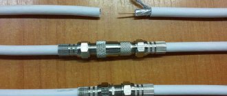
- F-connectors are a special metal structure that allows you to reliably connect two pieces of cable without the use of a soldering iron or additional insulation. The method is often used when, when moving the TV to the other end of the room, the available supply of cable is not enough or the damaged section needs to be replaced. This is the simplest and most economical method, as opposed to laying a new cable directly from the antenna.
Next, we will look at the practical application of each described method of connecting an antenna cable.
With the transition of analogue broadcasting to digital form, the requirement of televisions for the broadcast signal has increased. Residents of suburbs and villages now use TV tuners with amplifiers. Therefore, the quality of the connection of television wires came to the fore.
The best method for extending antenna cables
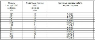
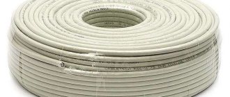
In order to extend the TV cable, you need to take care of a piece of the required length and, of course, the brand. You can rewrite the labeling or even take a small piece with you to the store.
The method of soldering the antenna cable for its extension is not optimal. The connection point will not be strong enough, and the wave resistance indicators will most likely not “fall” into the required values.
Therefore, experts recommend 2 other methods:
1) using F-connectors;
2) through a splitter.
Let's look briefly at each of them.
F-connection
Cable antenna cutting.
1-2. Remove a small part of the outer shell (1.5 cm).
3. Bend the braided screen towards the wire (contact with the conductor must not be allowed).
4. Remove the insulator.
5. Screw on the F-connector.
Both ends of the wires cut in this way are screwed onto the F-connector. If desired, you can additionally secure the place of twisting with electrical tape.
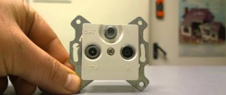
Splitter
This small box device is designed for creating TV antenna branches or connecting several receivers to 1 wire.
The splitter must be firmly secured in a vertical or horizontal position. And only after this, connect the sections of the cable antenna, cut as described above, with the F-connectors already screwed on.
Extension of TV cable using F-connectors
This option for connecting the wire involves visiting a store where you need to purchase two F-plugs (for each of the 2 ends of the cable) and one adapter - F-socket. It is recommended to take a piece of TV cable with you, since components are sold for different diameters. The tools you will need are a regular or construction (segment) knife and wire cutters.
Building up an antenna cable begins with preparing its sections:
- Make a careful cut into the outer shell. For ease of operation, the length of the cut should be greater than the length of the F-plug body. In the future, it can be adjusted by removing the excess part of the central core.
- Fold the casing in the opposite direction and remove it completely.
- Turn the copper shield and the foil underneath towards the remaining outer shell. To perform the procedure, they can be slightly incised. At this stage, pay attention to the possible presence of a coating of a thin layer of polyethylene or lavsan on the inside of the foil. These materials greatly impair the transfer of contact to the F-plug housing. To solve the problem, screw back half of the wrapped foil. This way the side with poor current transmission will be on the inside.
- Using a sharp knife, cut the insulation of the central core. Try not to leave notches on it, as they reduce strength and can lead to breakage.
- Take the F-plug and screw it onto the cable. It must fit snugly, since the fixation is achieved only by clamping force.
- Trim off any excess center core. Its edge should protrude 3-5 mm beyond the F-plug body.
If the diameter of the cable is smaller than the internal diameter of the F-plug, then before turning off the screen with foil, wrap electrical tape around the outer sheath.
This completes the preparation of the two ends of the cable. Now take the F-socket and connect the first and second plug to it. Fixation is ensured by screwing the movable head of the F-connector onto the thread of the adapter. The result will be a neat and reliable connection. In its place, you can also install a splitter, which will be discussed later.
Extending the cable using a splitter
This device is designed to distribute the input signal evenly. Accordingly, it has one incoming connector (labeled with the word “IN”) and several output connectors (labeled with “OUT”). Using a splitter, you can not only extend the cable, but also route it to two or three TVs at once.
The inlet hole on the splitter itself is similar in principle to the F-socket. Fixation occurs due to a threaded connection. The process of extending the cable is similar to that described for F-connectors, so there is no point in dwelling on it separately.
Screening and construction
RCA cables must be well shielded. This is true regardless of the application. In addition to the resistance on the cable itself, electromagnetic and radio frequency interference can introduce itself into the signal without shielding being in place to block it. As cables lengthen, these factors become increasingly important. Common types of shields are foil and braided copper or aluminum, with alternating foil and braid configurations being the most effective. Foil shielding works best against electromagnetic interference, while braided shielding works best against RF penetration.
Connecting TV wires by soldering
For this method you will need a soldering iron, solder and rosin (an alternative is soldering acid). You should also have basic soldering skills.
The method allows you to connect different cable variations. Let's consider step by step the process of soldering two cables with a single core and a double screen (copper braid + aluminum foil):
- On each cable, make a cut along the outer sheath 5-6 cm long.
- Unscrew the shell and the screens underneath it - copper mesh and foil.
- Cut the central core along with the insulation to a length of 2 cm.
- Cut off part of the insulation from the central core - the result will be some kind of step. When folding two parts of the cable, this design should ensure complete closure of the contact, with virtually no gaps.
- Bend the central core away from the insulation by 45 degrees. Tin it and solder it to the second part of the wire. In the absence of an assistant, before soldering, the cores can be tied with thin wire taken from a copper screen.
- Inspect the soldering results. If the cured solder has sharp edges or beads, remove them using fine-grit sandpaper or a file.
- Close the two steps cut from the insulation together, removing excess if necessary. Secure the resulting structure with insulating tape - 2-3 turns.
- Replace the foil on the two parts of the cable. On the inside it is covered with a non-conducting layer, so you need to properly wrap this part of the screen, ensuring contact between the conductive sides.
- Return the copper mesh - first one, then the other. To improve contact, wrap the area with several pieces of tinned wire of the same diameter. Then solder these parts.
- Unscrew the outer shell one by one. As a result, one should envelop the other. Secure the connection with insulating tape.
How to extend a video surveillance cable?
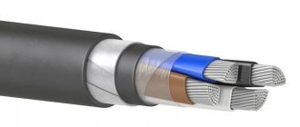
When moving video surveillance systems, we are faced with the fact that the current wire is not enough and it needs to be extended. Let's look at how to increase it without losing video quality. As we already know, to transmit a signal over a coaxial cable, a central conductor (usually a monocore) and a braid (multi-core) are used.
The connection method may depend on the type of coaxial cable and the environment in which the junction will be located.
We extend the outdoor coaxial video surveillance cable or twisted pair cable.
The junction location is outdoors, in the ground, or in other harsh environments. Provide a sealed protective box, placing the joint in it. For reliable fixation and better sealing, we use heat-shrink tubing. Under the influence of temperature, it contracts and securely fits the junction of our wires. If you use plastic distribution boxes and do not have sealed leads in them, you can additionally coat the rubber seals with sealant.
The central core of a coaxial cable can be single-core or multi-core.
To extend (connect) a single-core cable:
— One way is to screw two threaded coaxial F connectors onto the end of each cable and connect them together with an F socket. The advantages of such switching are that the central core of the conductor plays the role of a plug, and this will help to avoid additional signal losses. To crimp F connectors, no special tools are required, and the connection is resistant to mechanical stress.
— Connection or extension using coaxial connectors: two BNC video surveillance connectors (preferably crimped) on each side of the joint. They are connected to each other using the I connector (female-female).
To extend (join) a multi-core cable: - The central core consists of many thin, soft, intertwined strands. We strip and twist all the hairs of the central core together, dip it into neutral solder fat, and then, using a soldering iron, into the molten solder. As a result, the central core will become tinned and hard. Next, we connect the two wires in the same way as in the case of a monocore: using two F connectors and an F socket (barrel).
— Using coaxial connectors: two BNC video surveillance connectors (preferably crimped) on each side. They are connected to each other using the I connector (female-female). The multi-core cable will first need to be tinned, as in the previous case.
Other ways to extend CCTV coaxial cable:
— Twisting is not the best option for extending the wire, as the reliability of such a connection suffers. After extending the coax, try moving the joint; the image should not double and there should be no interference. Over time, the twist may oxidize, which will affect the image quality.
— Soldering the cable. This method is not suitable always and not everywhere. Since characteristic impedance is important for transmitting a video signal, it is not enough to simply ensure contact between two conductors.
We extend the video surveillance cable based on twisted pair.
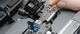
How to extend twisted pair cable? — It is best to extend a twisted pair cable using connectors and connectors: “pass-through modules.” First, you will need to crimp the two ends of the wire with rj-45 (8P8C) connectors. Next, they need to be connected with a “pass-through module”.
— As an alternative, there are pass-through adapters (utp extension cable) for terminating cross-connections.
— Extension by twisting is not the best option for extending the wire; the reliability of the connection suffers, and the places where the twists are oxidized. You can use this method to splice if you do not have another tool at hand.
— Extending the UTP wire by soldering. A long, difficult option, and not always possible.
Author: Dmitry Samokhvalov, technical editor of Rucam-Video.
Questions, comments and suggestions write to
Twisting method
Use this option only as a last resort, when you need to immediately provide a signal to the TV, and you don’t have F-connectors or a soldering iron with solder at hand. Twisting in any case will lead to a significant loss of signal quality, and during the connection of the central core it often breaks.
In general terms, the twisting technique is similar to soldering. You will need to prepare the two ends of the cable in a similar way, then fold them parallel to each other. First, twist the copper mesh and insulate the area with PVC tape. Then the central cores are connected. Considering the temporary nature of the work and the good insulation of the copper screen, the cores can be left as is - bending them to the outer braid is fraught with a break.
These are all methods that can be used to extend the antenna cable. The simplest option is to use F-connectors - they are not expensive and do not require special tools for installation. I recommend soldering when connecting two wires with different characteristics. To branch the signal to several TVs, use a splitter. Twisting is a temporary method that should be replaced with a more reliable one in the future.
Source
Installation and connection of cable KVK-P
Now you need to lay the KVK-P cable to each video camera, or rather to the place where you planned to place them. You can lay it indoors either in a plastic channel or simply on top of the walls.
On the street, if desired, it can be protected with corrugation, but not necessarily.
To protect the connection points between the cable from the recorder and the cable from the camera from snow and rain, mount a junction box on the wall and route the wires into it.
Next, remove the top layer of insulation from the cable, about 8-9 cm, and strip the two power cores. Press them with NShV tips.
Insert these wires into the male power connector. There are two connectors “+” and “-“. As we have already agreed before, the red wire will be the positive contact, the black wire will be the negative one.
After this, remove the insulation from the coaxial cable.
Carefully move the outer copper braid back so that not a single hair has accidental contact with the core in the center. Otherwise, the quality of the picture will be poor, or there will be no picture at all.
Expose the central core by 3-4mm and mount the BNC-F connector.
Insulate everything from above with a protective cap.
Next, install the video camera itself on the wall. You run the wires from it into the junction box where you just installed the BNC-F connectors.
Connect the connectors together and close the lid tightly.
To prevent moisture from getting inside, it is necessary to use a box with sealed cable entries on the sides.
All other video cameras on the walls of your house are connected in the same way. To each of them you will have to pull a separate KVK-P cable.
Connecting wires on the DVR
Now all the video surveillance cables need to be disconnected in the low-current cabinet. First, connect the DVR itself via an uninterruptible power supply.
Then you strip the second ends of the KVK-P cable, brought into the cabinet, in the same way as shown above. In this case, connect the power wires (red and black) to the corresponding terminal blocks “+V” and “-V”.
And insert the end of the coaxial cable, with the BNC-F connector installed, into the free socket of the DVR. Where it says Video In.
Do the same with the remaining video cameras.
All you have to do is set up the video surveillance by connecting the monitor to the recorder via VGA or HDMI connectors.
If the low-current cabinet is located far from the computer, you can use a laptop to configure it. And after that, output the signal to the monitor using a separate cable.
To safely use the monitor for other purposes, you can connect a computer to the HDMI connector, and cameras to the VGA connector. Then by changing modes you can easily switch pictures from different sources.
All software for setting up video surveillance must be included with the video cameras.
What is an RCA connector?
The RCA (AV) connector is popularly called a “tulip”. The standard is also called composite. This connector is widely used not only in video equipment, but also in audio equipment. It has a cylindrical shape. The signal contact is located in the very center. There is a ground contact in the form of a cylinder that covers the signal contact. The red connector is designed to transmit a two-channel audio signal in stereo mode regarding the right channel. The white connector is used for a monaural signal. Can also be used for the left channel of a stereo two-channel audio signal. Yellow—video signal transmission. As for appearance, this connector strongly resembles a real tulip.
Basic colors of tulip wires
"Tulips" are known in one-, two- and three-plug designs. However, the triple variety is more common. The dual audio cable consists of one red plug and one white, while the triple variant has the addition of yellow.
The basic color signals are yellow, white and red. Understanding what the colors of the tulip wires mean and how to connect them correctly is not difficult.
The yellow plug is used to connect video; white – for audio signal on the left side; red – for the audio signal of the right jack. In this case, take into account the correspondence of the color of the wire with the color of the input on the device.
If the TV has inputs with the same colors, then use the following decoding:
- on the tulip wire and the TV you need to find the inscription “IN” (which means “in”) or two arrows, also on the TV input there may be the designation “AV2”, and connect the wire;
- The designations on the TV may be “V” - video connection, “L” - left audio input, “R” - right audio input.
Thus, knowing what tulip wires are used for and what color is responsible for what, we connect: the yellow plug to the V-connector, the white one to the L-input and the red one to the R-input on the TV.
If there are three tulip plugs, and the TV has two inputs, then connect only yellow (to the video signal) and white (to receive a mono audio signal). The red wire is not used at all.
Screening and construction
RCA cables must be well shielded. This is true regardless of the application. In addition to the resistance on the cable itself, electromagnetic and radio frequency interference can introduce itself into the signal without shielding being in place to block it. As cables lengthen, these factors become increasingly important. Common types of shields are foil and braided copper or aluminum, with alternating foil and braid configurations being the most effective. Foil shielding works best against electromagnetic interference, while braided shielding works best against RF penetration.
The history of RCA wires
In the 1940s, the Radio Corporation of America was the first to use cables. The gramophone they created was the first product connected via an RCA wire. RCA's innovations in television included the development of electronic and later color television. The use of tulip cables grew along with the popularity of television devices, as they allowed video and audio to be transmitted between televisions and other electrical equipment such as speakers and VCRs.
Description RCA
RCA jack or composite (also called phono connector, or CINCH/AV connector, and also colloquially “tulip”, “bell”, AV connector) is a connector standard widely used in audio and video equipment.
The big disadvantage of such connectors is that when connecting, the signal contact pair (with voltage) is connected first, and only then the housing contacts. This can cause damage to devices at the time of connection if there is a potential difference between the cases, which often happened when connecting TVs to the TV output on video cards.
A standard RCA plug (in slang for “male”) looks like a central metal protruding contact pin with a diameter of 3.2 mm (3.18 for a 0.25 inch size), an outer open length of 9.0 mm (9.52/7. 92 mm for 0.375/0.312 inch sizes), with an internal closed length of 6.0 mm (5.56 for 0.219 inch size), surrounded by a metal round rim (8.0 mm minimum inner diameter; 8.33 for 0.328 inch size). The outer diameter of the rim depends only on its thickness and is not standardized.
The RCA (slang for "female") jack, typically a panel connector that the bezel fits over, has an outer diameter of 8.0 mm (8.33 for the 0.328-inch size) and a depth of 7.50 mm (7.14 for the 0.281-inch size). ), so the rim crimping jaws must have a slightly larger internal diameter.
In inexpensive versions, the space between the connector/collet and the rim/housing (internal insulator) is filled with simple plastic or polyethylene, in mid-price ones - with textolite washers or similar ones made of pressed fiberglass, in expensive ones - with heat-resistant Teflon or ceramics.
One of the main disadvantages of inexpensive connectors is their low heat resistance. Soldering cables with a cross-section of 0.823 mm² (18 awg) or larger requires a very long warm-up time at standard solder melting temperatures of 250 ° C - or much higher temperatures of the soldering iron tip, in order to increase the cumulative heat capacity of the tip, sometimes up to 500 ° C.
RCA pinout
| Composite analog video—— | Composite | Yellow |
| Analog audio signal | Left/Mono | White |
| Right | Red | |
| Center | Green | |
| Left (surround) | Blue | |
| Right (surround) | Grey | |
| Left rear (surround) | Brown | |
| Right rear (surround) | Tan (tan) | |
| Subwoofer | Purple | |
| Digital audio | S/PDIF | Orange |
| Component analog video (YPbPr) | Y | Green |
| P.B. | Blue | |
| PR | Red | |
| Component analog video/VGA (RGB/HV) | R | Red |
| G | Green | |
| B | Blue | |
| H (Horizontal Sync) / S (Composite Video Sync) | Yellow | |
| V (Vertical sync signal:) | White |
Different signals use a different connector color defined by a standard, but multichannel audio (7.1 onwards) still does not have standard colors.
If you use audio output to the TV speakers, it is converted to the left channel (white connector).
Composite A/V Cable 3×RCA-TRRS is used to transmit composite video signal and stereo audio signal. It is often called “AV TV cable”.
7 options for AV cable wiring
On one side of the cable there are three RCA plugs (“bells”). RCA plugs are assigned specific colors according to their purpose. ⚠ If you use an incompatible cable, the meaning of the colors will be different!
• White – Left audio channel “L” • Red – Right audio channel “R” • Yellow – Video signal “V” The “ground” contacts of all three plugs are interconnected in the cable. In pinout tables, the common pin is designated "G" (Ground).
On the other side of the cable there is a 4‑pin TRRS plug (“jack”). The developers come up with the pinout of this plug in this cable at their discretion. At the end of the article there is a table of pinouts of the TRRS “Jack” plug for some manufacturers in alphabetical order. The numbering of jack contacts begins with the tip of the plug; 2, 3 contacts - rings; Contact 4 is the base.
Relevance of the RCA connector
Until recently, the RCA connector was popular and in demand. With its help, a variety of devices were connected to TVs: acoustics, amplifiers, VCRs and even DVD players. The reason for this is simple: RCA was an almost ideal option for transmitting analog signals (video and audio). It was also often found in sound cards for computers. Moreover, thanks to proper wiring, specialists used RCA to connect the computer to the TV, which served as a monitor.
But today it can no longer be said that RCA connectors are relevant. They are being successfully replaced by other interfaces that are considered progressive. For example, this is HDMI, Display Port, and so on. RCA is still going strong thanks to numerous converters and adapters that can be used to connect almost any equipment. Yes, the connector from Radio Corporation of America is still found even in modern televisions. But why use this connector if you can enjoy 4K content on a huge screen? After all, you need to remember that through RCA connectors you can transmit content in a maximum of HD or FHD resolution.