Even the simplest garage needs lighting, but if the wiring is done in a hurry, it would be unreasonable to expect it to be reliable and fireproof. When creating proper working conditions in this room, one must not neglect the rules for working with electrical wiring, otherwise the consequences can be the most unpredictable. In this article we will tell you how to do electrical wiring in the garage with your own hands, adhering to the standards and regulations.
In cooperative garages
In auto cooperatives, each garage has a power supply, the condition of which must be taken care of by an electrician, but as for indoor wiring, here you can improvise, of course, within the permissible limits. Therefore, you will have to develop an individual wiring diagram, taking into account the allocated or maximum permissible power.
Find out what power the machine is installed at the input. If 10 A, then you can only count on the fact that in the garage, in addition to lighting, it will be possible to connect a low-power drill, grinder and the like to the network, and even then not at the same time. When the input machine is designed for an operating current of 16 A, then it will be possible to use low-power household electric welding for a short time. With a 25 A circuit breaker installed, there will be no special power restrictions.
Line routing
Electrical wiring in the garage is carried out in three stages:
- Preparation;
- external wiring;
- internal laying.
Preparation
The preliminary stage includes cutting wires and preparing walls. It is necessary to cut the wires taking into account a length reserve of 150 mm for each branch. The walls are marked in accordance with the diagram. The most convenient way to mark is with a marking cord. To do this, it is fixed at the starting point, then stretched to the next branch or end point of the wiring. Then the cord is pulled along the length of the wall, pulled to the side and released down. Ultimately, a painted mark remains on the walls, which later serves as a marking. The main thing is to pull the cord only vertically or horizontally so that the print matches the marks on the diagram. In this regard, it is possible to use a small weight on a string and a building level.
Next, you should prepare everything that you will definitely need for electrical wiring in a concrete garage:
- pliers;
- set of screwdrivers;
- hammer;
- chisel;
- wire cutters;
- electric drill;
- insulating tape;
- perforator;
- fastening elements;
- indicator screwdriver.
Upon completion of the marking work, you should begin preparing grooves for electrical wiring in the garage. It is most convenient to chisel the walls using a grinder with a concrete disc, a hammer drill or a chisel with a hammer. It is recommended to make the depth no more than 20 mm. The width is selected in accordance with the cross-section of the core. In a brick garage there is no need to trench the walls. The wiring in the garage fits perfectly into the seams between the rows.
Similar: How many amperes are in a 220V outlet: determine the current strength
External wiring
External wiring should only be carried out by a qualified electrician. If the wiring will pass through the air, then you need to install an intermediate support post in case the length to the pole is more than 25 m. In this case, it is necessary to take into account some height requirements:
- above the road from 6 m;
- above pedestrian paths from 3.75 m;
- above the garage from 2.75 m.
This last requirement is likely to be problematic since garages are often not built very high. Then it is recommended to install a bent steel pipe.
If the wire is laid from below, then it will be necessary to dig a trench from the central power line to the switchboard and put a power copper cable (VBBShV) into it. The main thing in the foundation is not to forget to leave a hole for insertion into the inside of the garage.
To protect the line from mechanical stress, it is better to pack it in a steel box and additionally cover it with a rubber band on top. Under the garage foundation, the wire also needs to be covered with a pipe with a diameter twice the cross-section of the core. The outer part of the pipe should protrude no more than 50 mm. The disadvantage of laying a line on land is the high cost and complexity of the work. True, there is one advantage - this method is the most durable.
Making a wiring diagram
To properly create a wiring diagram, make a list of electrical appliances that you plan to use in the garage. The number of lamps and their location must be taken into account.
If the garage is used only for parking and minor car repairs, then there is no need for a large number of sockets and lamps, but you also don’t need to save much. Above the workbench or near the entrance, you can install several sockets and a two-key switch so that you can divide the lighting lines into groups.
A multi-use garage should have good lighting and plenty of conveniently located outlets. It is also necessary to ensure safe lighting of the inspection pit.
How to install electricity in an individual garage?
In order to connect an individual garage to the electrical network, you need to contact a resource supply organization. It does not matter who applies: an individual or an organization. The connection is made on a general basis, as stated in PP No. 861 dated December 27, 2004. The entire procedure consists of 2 stages.
Stage 1 - Obtaining permission
Conducting electricity anywhere (to a site, to a house, to a garage) is possible only after obtaining permission from the company supplying electricity. What documents are needed?
In addition to the application for connection, power engineers must provide:
- a copy of the owner's passport;
- a copy of the title deed;
- copy of TIN;
- a list of all devices available in the garage, indicating their power;
- technical documents for the garage;
- a garage plan, which shows the location of electricity poles, gas, water and sewerage pipelines and the places where the wiring is installed;
- consumption calculation.
- send by Russian post;
- bring it personally to the company;
- remotely.
The application and documents can be submitted in 3 ways:
The application is considered within a month (if submitted in person) or within 45 days (if sent by mail) . After reviewing the application, the supplier company will send the owner 2 copies of the contract for the provision of electricity connection services and technical conditions (TU). If everything is satisfactory, then the contracts must be signed, and one copy must be sent back to the company.
Everything must be clearly and clearly stated in the contract. The exact connection period must be indicated (no more than 6 months).
Stage 2 - Connection
On the appointed date, energy company specialists will come to the specified address and make a connection from the pole to the input switchboard, seal the meter and draw up a subscriber connection certificate.
The layout and installation of electrical wiring will be carried out in accordance with current standards and in compliance with safety regulations.
What to include in the diagram?
Any garage must have an RCD (residual current device) installed. Although this device is not cheap, it will protect the owner from electric shock. The rated current of the RCD must be selected in accordance with the load current of the electrical wiring line, otherwise the device may not operate at the right time.
Also, you should not save on purchasing circuit breakers - it is better that each line is connected separately. Of course, it is necessary to take into account the total power of the connected devices so that the cross-section of the wire to be laid can be calculated.
Simple scheme
Often, owners of garages used only for car storage are limited to installing a paired circuit breaker at the entrance, one or two sockets and several lamps, which are controlled by a single-key switch. This scheme has its advantages: to pick up a car from the garage or put it there, you just need to turn on one switch, and the light will be on throughout the entire room.
One socket is connected directly to the machines, the second is included in the same circuit with the lamps. When leaving the garage, you can be sure that when you turn off the lights, you have cut off the power to the distant outlet. Even if the garage owner accidentally forgets to turn off the charger, it will turn off along with the light. The simplicity of the design implies some limitations. So, all 4 lamps will turn on at the same time, and the second socket is only suitable for powering low-power devices through it, otherwise the switch contacts will burn out.
Electrical wiring diagram for a garage with an inspection hole
Now let's look at the electrical circuit of a garage with an inspection pit. There are 5 lines coming from the input electrical panel:
- Socket group 1.
- Socket group 2.
- Lighting group 1.
- Lighting group 2.
- Lighting of the inspection pit.
The electrical panel contains an input circuit breaker, an RCD and several circuit breakers - each for its own group. As for the lighting of the inspection pit, it is carried out through a transformer that reduces the voltage to 12 or 36V.
Video: wiring diagrams
On the Internet you can find photos of a wide variety of electrical wiring diagrams in the garage.
Calculation of the quantity of materials
Once the electrical wiring diagram in the garage has been drawn up, you will need to move on to the second stage - counting consumables. First, the wires are counted. Electricity is supplied both inside and outside the garage, so it is necessary to purchase materials for everything. Installation of the external branch should be carried out with copper conductors with a cross-section of 10 mm² or more.
Similar: How to choose a soldering iron for your home
To correctly calculate the wire cross-section, you need to accurately determine the electrical appliances that will need to be installed. For sockets, conductors with a cross-section of 4 mm² are used, and for switches - 1.5 mm². As for the length, they certainly buy it with a reserve, since the wire is cut into segments: from connectors to the panel, from switches to light bulbs. Each branch requires a reserve of 150 mm.
Next comes a careful calculation of the number of sockets. You need at least two of them: for an extension cord and a stationary electrical appliance. At least two switches are also required: for the pit and for the main lighting. Special attention should be paid to lamps. LED and fluorescent light bulbs have become widespread among the population.
It is also worth counting the number of fasteners, corrugated pipes or cable ducts.
Purchasing consumables
Having drawn up a diagram, purchase everything you need to complete the work. We will do this thoroughly and for a long time, so we will consider installing hidden wiring. To be fair, there are other ways to run wires in the garage, which you can read about here.
In order not to waste precious time and effort in vain, purchase or rent a wall chaser and a hammer drill with a set of drills and a concrete bit, the diameter of which will allow you to install socket boxes and distribution boxes in the holes cut with it. We won’t even talk about a chisel and a hammer, since such a tool should be in any garage.
For further work you will need:
- Distribution panel – 1 pc.
- Electricity meter – 1 pc. (if needed).
- RCD – 1 pc.
- Socket boxes - according to the number of mortise switches and sockets.
- Distribution boxes - in each place where there will be a outlet for sockets and switches.
- Automatic switches - type and quantity according to the diagram. It may be necessary to install some machines separately, for example, near a grinding machine, compressor, etc.
- Wiring. It is better to purchase a copper three-core wire. For lighting - 1.5 mm2. For sockets - 2.5 mm2. For wiring in the garage to the panel - 4 mm2. Quantity - according to the scheme + 10% for unaccounted terminals in distribution boxes and socket boxes. In order to power more powerful consumers, it is recommended to run a separate wiring line from the distribution panel to the desired location.
- Corrugated PVC pipes for electrical wiring. The diameter and quantity are selected to match the existing wiring. If the wiring will pass through flammable materials, then a metal corrugated pipe should be laid in such places.
- If there is a point in the garage for connecting 380V electrical equipment, then you need to take care of purchasing a specific outlet and the appropriate cable.
- Sockets. Their number should be sufficient for convenient use. It is important to remember that there can be several lamps above the workbench - they can be connected either through junction boxes or directly into sockets.
- Switch. Someone prefers to turn off the lighting in the garage with one switch, another likes to divide it into several groups, and a third installs a switch under each lamp - everyone can do it in a way that is convenient for them to use.
You can make a distribution panel yourself, like the author of this video:
Electrical wiring in the garage
To bookmarks
General requirements
The basic requirements that must be taken into account during electrical installation at almost any facility are described in the Rules for the Construction of Electrical Installations (PUE) in Chapter 2.1 (electrical wiring), as well as, on certain issues, in a number of other chapters. In this article we will look at the basic requirements and standard diagrams, knowledge of which is necessary in order to make electrical wiring in the garage with your own hands.
- How to install electrical wiring in a garage?
Any electrical wiring begins with choosing a method for its installation. Typically, garage wiring is done openly to reduce costs. If the garage is made of cinder block, brick, iron, i.e. any non-combustible material, then laying can be done in almost any way, from laying in corrugation to direct laying (for example, on brackets), but if the garage is made of wood or any other combustible material, this imposes much more restrictions on the possible methods of laying, in which case It is better to carry out electrical wiring in a box (cable channel).
Read more in the article: “Installation of electrical wiring”
- Which cable (wire) should I use for wiring in the garage?
For wiring, it is necessary to use cables with aluminum (AVVG brand) or copper (VVG brand) conductors, and it is better to give preference to copper:
The use of flexible wires such as PVA or SHVVP cords is prohibited! They are used only for connecting mobile, portable and stationary electrical appliances to the network or for extension cords.
- What cable size should I use?
The cross-section of the cables used for wiring is determined based on the power of the electrical appliances connected to them; knowing this power, you can calculate the cross-section using our online calculator. As a rule, cables with a cross-section of 1.5 (or 2.5) mm2 for copper, or 2.5 (or 4) mm2 for aluminum are used for electrical wiring.
- What electrical safety requirements must be observed?
Modern requirements for electrical safety state that new buildings must have grounding (7.1.13. Electrical receivers must be powered from a 380/220V network with a TN-S or TN-CS grounding system), in domestic realities, it is implemented using the TN-CS system , where at the input the neutral conductor is re-grounded and divided into a working zero and a protective conductor (read more about how to ground using the TN-CS system here), therefore the cables must have a grounding conductor, i.e. For electrical wiring, you must use three-core (for a single-phase network) or five-core (for a three-phase network) cables.
It is also worth considering that in a garage there is often a need to use a carrier (portable lamp.) But in accordance with the requirements of the PUE, the use of carriers with a voltage of 220 Volts is prohibited ; paragraph 6.1.17 states that for powering portable lamps in areas with increased danger and especially dangerous ones, a voltage of no higher than 50 V should be used, and if they will be used in cramped conditions or the worker will be in an uncomfortable room (and often this is the position of the car mechanic), then the voltage should not exceed 12 V).
You can get this voltage in the garage in two ways: by powering the carrier from a 12V car battery or from a step-down transformer. Of course, you can use the first step-down transformer you come across that meets the requirements, but it is much more rational to purchase a complete box with a step-down transformer, a circuit breaker and a socket, for example, YaTP 0.25 220/12B (manufactured by different companies, one example of a name for easy search on the Internet stores - IEK MTT12-012-250), its power is 250 VA, there are more powerful options, they are selected based on needs (number and power of lamps).
You can mount it in an electrical panel or on the wall in any convenient place (but not in an inspection hole) and use it to power either a portable lamp or stationary 12V lamps.
In the inspection pit itself there are two dangerous factors - cramped working conditions and often damp, to the point of groundwater drainage. Therefore, there should be no sockets or stationary lamps in the pit that operate on 220V . If it is necessary to install a lamp or socket for carrying, their connection must be made from a step-down transformer.
All lamps with a voltage of 220V, including portable ones, must be located at a height of at least 2.5 meters (to prevent electric shock from accidental contact).
- What lamps and sockets should I use for lighting in the garage?
A garage space, as a rule, is characterized by factors such as humidity and dust, so sockets and lamps should be selected with a dust- and moisture-proof housing, i.e. with a degree of protection IP65 or higher (for more information about the degrees of protection of electrical equipment housings, read the article: IP protection classes - decoding).
In addition, sockets in a 220 Volt network must have a grounding contact.
The required number and power of lamps can be calculated using our online calculator for calculating lighting by room area.
Wiring diagram
Let's consider a typical version of electrical wiring in a 220-volt garage. Any electrical wiring begins with an input switchgear (electrical panel), abbreviated as ASU, in which protection devices (circuit breakers, RCDs, etc.) and an electric meter (if necessary) will be installed in the future, while the ASU itself, as a rule, is better installed near the entrance to the garage.
On the front or side panel of the ASU, or next to it, light switches for the main (ceiling) lighting and a socket block are installed. It is better to install local lighting switches directly next to these lamps, that is, if you have an additional lamp installed above your workbench, then it is better to install the switch next to it. It is useful to install one or more outlets on the opposite wall, near the workbench (desktop), so as not to scatter extension cords throughout the garage.
It is not safe to lay 220V lines in the inspection pit and, based on the above, this is completely prohibited. Therefore, you need to limit yourself to 12V lamps; you can also place a 12V outlet to connect a portable lamp or tool with a reduced power supply voltage.
If you have a compressor, a separate line is also laid to it.
Based on all of the above, the arrangement of electrical equipment in the garage will look something like this:
NOTE: Distribution boxes are shown in gray where the wires of the 220V lines are connected, and in green - 12V.
Then the 220V electrical wiring diagram (sockets, compressor, as well as working and ceiling lighting) in the garage will look like this:
The distribution boxes are labeled with numbers; you will see their wiring diagrams below. Having drawn up the wiring diagram, you should calculate the length of the lines for purchasing the cable. The core cross-sections for lighting lines are usually chosen to be 1.5 mm², and for sockets - 2.5 mm². The cross-section of the cable cores for connecting the compressor is selected based on its power; in the diagram, 2.5 mm² is conventionally taken (as a rule, this is enough). You can calculate more accurately using our online calculator.
We also present basic connection diagrams separately for each cable in accordance with the wiring diagram drawn up above:
Here you see the connection of a two-button switch to control the ceiling lighting and the wiring to sockets. We discussed this issue in more detail in this article, and if you want to control the lights in the garage from several places, then the article on pass-through and crossover switches will be useful to you.
The cable to the compressor is not shown in these diagrams - it comes directly from the panel.
Now let's look at laying 12 Volt networks. Using the example of a box with a step-down transformer of the YaTP type, its connection diagram will look like this:
NOTE: When choosing a cable for a 12 Volt network, after calculating the power cross-section, it must also be checked for voltage loss using our other calculator.
The 12 Volt wiring diagram will look like this:
It is rational to conduct wiring into the pit in a screed, laying PVC, HDPE or a metal pipe in advance.
Cable connection diagrams in junction boxes, according to numbering, in the previous figure:
The second distribution box is located in the inspection pit; it is where the cables for powering all the lamps and the socket for the portable light source are disconnected
Electrical panel diagram
In conclusion, we will consider the layout and diagram of the garage electrical panel (GSU).
The diagrams contain the following letter designations:
- L—phase;
- N—working zero;
- PE - ground (protective conductor).
The garage is usually a damp place, and the presence of flammable substances (oil and fuel) makes it even more dangerous. Therefore, it is mandatory to install an RCD on the socket groups; it is not necessary on the compressor, but its engine and receiver must be grounded. It is also better to connect the step-down transformer line to an RCD.
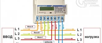
Let's give two diagrams of electrical panels, the first is for garage societies and cooperatives, where the garage is often connected to an overhead line and a meter is installed in the electrical panel (we talked more about the wiring diagrams for electric meters earlier in this article):
The second scheme is suitable for residents of cottages and private houses, when the garage is powered from the electrical distribution panel of the house, so a separate meter is not needed. Just as there is no need to separate the zero at the input, this circuit is suitable for TN-CS, TN-S, TT grounding systems.
Was this article useful to you? Or maybe you still have questions ? Write in the comments!
Didn’t find an article on the website on a topic that interests you regarding electrical engineering? Write to us here. We will definitely answer you.
↑ Up
5
https://elektroshkola.ru/elektroprovodka/elektroprovodka-v-garazhe/