19.1 Two-speed induction motors of various speeds
Three-phase induction motors can be designed for more than one speed, either implemented with different windings differing in the number of poles, or with only one winding but constructed in such a way that it can be connected externally with a different number of poles.
For this reason, some types of three-phase induction motors with different speeds are also called pole-switching motors. Figure 19.1 shows schematically the various types of windings and also their connections which are now most commonly used in the design of motors of various speeds, the second being the most commonly used of all.
Figure 19.1 – Connection systems for three-phase asynchronous motors with different speeds
This type of motor has a squirrel-cage rotor and is mainly used in the operation of machine tools and fans, and, as regards the types of construction shown in Figure 19.1, their main characteristics are the following:
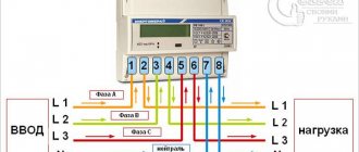
11-15. Connection diagram for a two-speed asynchronous motor
In Fig.
11-22 shows the start control circuit of a two-speed asynchronous motor. To obtain a lower speed, when the number of poles is doubled, press the Start button M and the stator windings are connected to the network with clamps, i.e., in a triangle. With this switching on, the stator winding creates a larger number of poles. Greater speed is obtained by pressing the Start button B, when contactors 1B and 2B are turned on and the stator windings are connected by connecting the sections in parallel with a double star. With this switching on, the stator winding creates a smaller number of poles. Switching to higher speed can be done without first pressing the Stop button, i.e. on the go. Rice. 11-22. Starting diagram for a two-speed asynchronous motor.
© 2021 Scientific Library
Copying information from the page is permitted only with a link to this site
Starting three-phase two-speed motors. Dahlander connection
19.2 Two-speed motors with Dahlander connection or pole-changing
The most used type of asynchronous three-phase motors with various speeds (one can say that almost the only one currently used) is the full-winding motor with Dahlander connection and that is why this motor will be described in detail. Figure 19.2 shows the winding of a three-speed asynchronous motor with a Dahlander connection, showing both internal connections and connections with a terminal block to the network, in two operating positions. This motor is designed to operate with four poles when connected in delta and two poles when connected in double star according to the winding phases U1 - V1 shown in the figure.
Figure 19.2 – Internal connections, delta and double star, Dahlander motor windings, with 4 and 2 poles
As shown in Figure 19.2, when starting at a lower speed, it is sufficient to apply the network voltage of the terminal connection curtains, when making a triangular connection between the three phases inside the motor. Conversely, for high speed, two operations must be performed: first, U1, V1 and W1 must be short-circuited, and then the mains voltage U2, V2 and W2 must be applied to the terminal connection. Conclusion based on the above: to automatically start a motor with a Dahlander connection, three contactors are required.
Also in Figure 19.2 you can see that when the motor is connected at low speed, a double number of poles is formed due to the fact that all the stators of one phase are connected in series, while for higher speed the stators of each phase are connected half in parallel, thus getting half the number of poles compared to the previous description.
Let's move on to the description of the control and protection circuits most often used for the operation of motors with a Dahlander connection, and presented in Figures 19.3 and 19.4. The first is a simple start at any of the two speeds and the second is the same type of start, but with two necessary circuits so that at each of its two speeds the engine can start in both directions without distinction (the same).
Winding diagrams of a two-speed asynchronous motor
24. WINDING DIAGRAMS OF MULTI-SPEED THREE-PHASE INDUCTION MOTORS
Multi-speed three-phase asynchronous motors are usually manufactured for two, three and four rotation speeds.
Two-speed motors at multiple rotation speeds (number of poles 2р=4/2; 8/4; 12/6) have one two-layer winding on the stator, which can be switched to two different numbers of poles 4 and 2.8, and 4.12 and 6 .
Two-speed motors for multiple rotation speeds (2р=6/4) have two separate windings located in the same
Rice. 48. Detailed diagram of a two-speed two-layer winding with 2p=4/2, z=24, a=1 and phase connection Δ/YY
Fig. 49. Expanded diagram of a two-speed two-layer winding at 2p=4/2, z=36, a=1 and phase connection Δ/YY
Rice. 50. Detailed diagram of a two-speed two-layer winding with 2p=8/4, z=36, a=1 and phase connection Δ/YY
same grooves. In this case, the windings are made single-layer with concentric coils. Coil groups are usually connected in series (number of parallel branches a = 1), and the phases are connected in a star to avoid closed circuits when the second winding is connected to the network.
Motors for three and four speeds also have two separate windings. At three rotation speeds, one winding switches to two different numbers of poles, and the second has an intermediate
Rice. 51. End circuit of a two-speed two-layer winding with 2р=8/4, а=1 and phase connection Δ/YY
exact number of poles. For four-speed motors, each winding switches to two numbers of poles.
In Fig. 48-56 show the most common diagrams of stator windings of multi-speed motors.
For small stator bore sizes and the number of poles 2р=4/2, two-layer windings are used (Fig. 48, 49), in which some of the coils are placed on the bottom of the groove, and some are placed at the wedge (in the upper layer of the winding). For example, in the winding, the diagram of which is shown in Fig. 48, coils in slots 1.2—7.8; 3.4—9.10 and 5.6—11.12 are placed on both sides on the bottom of the groove, and the coils in the grooves are 21.22—3.4; 23.24—5.6 and 19.20—1.2—on both sides of the wedge. This makes it easier to lay the winding, since you don’t have to lift
the upper sides of the first coils when inserting into the grooves of the last step coils. The remaining coils are laid as in a conventional two-layer winding.
Two-layer two-speed winding is manufactured in the form of coil groups, the laying of which is carried out as in a conventional two-layer winding. The connection of the terminals of the coil groups of a two-speed winding can also be presented in the form of a circular diagram. In Fig. 51 and 53 show end circuits corresponding to the expanded circuits shown in Fig. 50 and 52.
Rice. 52. Detailed diagram of a two-speed two-layer winding at 2р=8/4, z=36, a=2 and phase connection Δ/YY
The coil groups in two-layer two-speed windings in each phase are divided into two parts in such a way that when connected to a smaller number of poles, the current in half of the coil groups changes direction. With a larger number of poles, the direction of the current in all phase coil groups is the same. In the figures, the direction of the current in the groups is shown when connected to a larger number of poles by a solid arrow, and when connected to a smaller number of poles by a dotted arrow. The direction of current in the diagrams in the first and second phases is taken from the beginning of the phase to the end, in the third phase - from the end to the beginning.
Consider, for example, the circuit shown in Fig. 51. It follows from it that the conclusions of the coil groups must be interconnected: 2-13, 4-15, 10-21, 12-23, 18-5, 20-7. The beginnings of the phases are connected to the terminals: 8С1—1—24; 8С2—8—9; 8С3—16—17; 4С1 —14—19; 4С3—3—22; 4С2—6—11.
When the circuit is switched on to a larger number of poles, the beginnings of phases 8С1, 8С2 and 8СЗ are connected to the network. In this case, the current in the coil groups of each phase is directed equally; in the first and second phases - from beginning to end (from odd to even numbers), in the third - from end to beginning. When switched on to a smaller number of poles, the current in half of the coil groups of each phase changes direction to the opposite (groups: 1-2,3-4, 11-12, 13-14; 15-16; 23-24).
Rice. 53. End circuit of a two-speed two-layer winding with 2р=8/4, a=2 and phase connection Δ/YY
Rice. 54. End circuit of a two-speed two-layer winding with 2р=4/2, a=1 and phase connection Δ/YY
Rice. 55. End circuit of a two-speed two-layer winding with 2р=12/6, a=1 and phase connection Δ/YY
Rice. 56. End circuit of a two-speed two-layer winding with 2р=12/6, а=3 and phase connection Δ/YY
In a multi-speed motor, one of the windings is simultaneously connected to the network (Fig. 57). If this winding switches the number of poles and is switched on at high speed, then the remaining terminals from it when connecting the phases Δ/YY are short-circuited (terminals
Rice. 57. Scheme for switching on electric motors at four rotation speeds
12С1, 12С2, 12С3 and 8С1, 8С2, 8С3 when switched on to six and four poles, respectively). The terminals of the second winding remain open.
Source
19.3. Starting a two-speed pole-changing motor without rotation inversion
The electrical characteristics of the control and protection elements necessary to perform this type of start-up must at a minimum be:
Let's move on to a brief description of the startup process, both at low speed and at high speed:
The pushbutton system auxiliary contacts (S1 and S2, 21–22) act as safety double shutters for the pushbutton system in the event that both breakers are attempted to be pressed simultaneously, so that neither contactor is activated and these contacts can be removed if There are mechanical type protective curtains between K1 and K2.
Figure 19.3 – Power and control circuits for starting a pole-switched motor
How to connect a multi-speed asynchronous motor
Connection diagram for a multi-speed asynchronous electric motor with a squirrel-cage rotor Triangle (or star)\\ double star —— D/YY.
Lowest speed - D (triangle (or star Y): 750 rpm
2U, 2V, 2W are free, voltage is supplied to 1U, 1V, 1W. The highest speed is YY. 1500 rpm 1U, 1V, 1W are closed to each other, voltage is supplied to 2U, 2V, 2W. Two-speed motors have one pole-switching winding with six lead ends. The winding of motors with a rotation speed ratio of 1:2 is carried out according to the Dahlander scheme and is connected into a triangle D (or into a star Y) at the lowest rotation speed and into a double star (YY) at the highest rotation speed. The connection diagram of the windings is shown in the figure. Average speed. 1000 rpm The 1000 rpm winding is connected independently of the others with its own starter, which does not participate in the Dahlander circuit. Starting a two-speed pole-changing motor without rotation inversion for the Dahlander circuit. The electrical characteristics of the control and protection elements necessary to perform this type of start-up must, at a minimum, be: Contactor K1, for turning the engine on and off at low speed (PV). The power must be the same or exceed the In of the motor in a delta connection and with service category AC3. Contactors K2 and K3, for turning the motor on and off at high speed (GV). The power of these contactors must be the same or exceed the In of a double star connected motor and service category AC3. Thermal relays F3 and F4, for overload protection at both speeds. Each of them will measure the In used by the engine at the protected speed. Fuses F1 and F2, for short circuit protection. must be of type AM and with a power equal to or greater than the maximum In of the engine, in each of its two speeds. Fuse F5, to protect control circuits. Push button system, with a single stop switch S0 and two double movement switches S1 and S2. Let's move on to a brief description of the starting process, both at low speed and at high speed: a) starting and stopping at low speed (PV). Start by pressing S1. Closing the K1 circuit contactor and starting the delta-connected engine. Automatic power supply via (K1, 13–14). Opening K1, which acts as a shutter so that although S2 is driven, the high speed contactors K2 and K3 are not activated. Stop by pressing S0. b) starting and stopping at high speed (GV). Start by pressing S2. Closing the star contactor K2, which forms the motor star in the event of a short circuit: U1, V1 and W1. Closing the contactor K3 (K2, 21–22) so that the motor operates with a double star connection. Automatic power supply via (K2, 13–14). Opening (K2, 21–22) and (K3, 21–22), which act as curtains to ensure that K1 is never closed while K2 or K3 is closed. Stop by pressing S0. The pushbutton system auxiliary contacts (S1 and S2, 21–22) act as safety double shutters for the pushbutton system in the event that both breakers are attempted to be pressed simultaneously, so that neither contactor is activated and these contacts can be removed if There are mechanical type protective curtains between K1 and K2.
Repairman's Guide
Three-phase motors that allow variable speed are very often used in air coolers in order to provide a change in air flow in accordance with changes in its temperature: low speed (MS) at low temperatures, for example in winter, and high speed (HS) at high temperatures. temperature, for example in summer (see section 20.5). As a rule, cooling towers are also equipped with two-speed motors (their operation is discussed in detail in Section 73). In Fig. Figure 65.1 shows a version of a cooling tower equipped with a two-speed motor (item 1) to drive a centrifugal fan (item 2).
Two-speed motor connection diagram
A major overhaul of a lathe is in progress. Main engine - two-speed
At a time when frequency converters for asynchronous motors were a luxury (more than 20 years ago), industrial equipment used DC motors, which had the ability to regulate the speed, if necessary.
This method was cumbersome, and along with it another, simpler one was used - two-speed (multi-speed) motors were used, in which the windings are connected and switched in a certain way according to the Dahlander circuit, which allows you to change the rotation speed.
Electronically controlled variable speed DC motors are used in high value industrial equipment. But two-speed motors are found in machines manufactured in the USSR in the 1980s in the middle price category. And I personally had problems connecting, due to confusion and lack of information.
The latest examples are a special lathe. execution, sawmill. Details will be below.
The design of the windings resembles a delta connection; therefore, the switching can be associated with a star-delta connection. And it's confusing.
The “Star-Delta” circuit is used for easy starting of motors (the speed in both modes is the same!), and two-speed motors with winding switching are used for switching operating speeds.
There are engines not only with two, but also with a greater number of speeds. But I will talk about what I personally connected and held in my hands:
Two-speed asynchronous electric motor
Less theory, more practice. And as usual, from simple to complex.
Definition of connection diagram
Before choosing one or another scheme for connecting a motor to 220 V, it is necessary to determine what the connection diagram for its winding is and at what rating it can generally be operated. To do this you need:
- Find and study the technical table on the engine. characteristics .
The information field contains all the important information - designation of the type of connection ∆ - triangle or star - Y , power, number of revolutions, voltage (220 or 380, or 220/380) and the possibility of connecting according to a specific circuit.
- Open the terminal box and verify in practice that the assembled circuit is correct.
The beginning and end of each winding is signed in accordance with the above alphanumeric nomenclature. The user remains to study the connection diagram using jumpers: according to what scheme the connection is made - star or triangle.
Note! If the nameplate (table with information) indicates the Y and only 380V, then when it is connected in a triangle, the winding will burn out. Only professional electricians can upgrade such a 220V motor. Therefore, there is no reason to modify it, especially since today there are many copies that can operate alternatively - both 220 and 380 volts.
Opening the terminal box Source pikabu.ru
Two-speed asynchronous electric motor
The windings of a two-speed motor look like this:
Two-speed motor diagram
When connecting the terminals U1, V1, W1 of such a motor to a three-phase voltage, it will be connected to the “triangle” at a reduced speed.
And if the terminals U1, V1, W1 are connected to each other, and power is applied to the terminals U2, V2, W2, then you will get two “stars” (YY), and the speed will be 2 times higher.
What happens if the windings of the vertices of the triangle U1, V1, W1 and the midpoints of the sides U2, V2, W2 are swapped? I think nothing will change, it's just a matter of names. Although, I haven't tried it. If anyone knows, write in the comments to the article.
Control circuit for two-speed asynchronous electric motor
Step regulation. Modern woodworking machines are distinguished by the variety of basic kinematic schemes of the main movement. The main drive consists of an engine, a transmission and a working element. The engine in most cases is an electric motor. Transmissions from the engine to the working body are diverse: belts, gears, chains, direct connection of the engine shaft with the working body, etc. Working bodies can have one or more tools. The process of cutting wood has a stochastic nature of the load.
The listed factors have a significant impact on the choice of electric motor and control system that will be adopted to drive the main movement.
In modern woodworking machines to drive the main movements, the most common are asynchronous short-circuit AC electric motors, hydraulic motors, and in some cases DC motors. Such equipment is characterized by high cutting speeds at spindle speeds from 3000 to 24,000 min-1. Most main motion drives have a constant speed. Along with this, adjustable drives are increasingly being used to ensure rational cutting conditions.
One of the simplest methods is step control using step pulleys in variable transmission and gearboxes. In modern designs of gearboxes, switching is done remotely using friction disk electromagnetic clutches (plywood planing machines) or systems with hydraulic mechanisms. Increasing the smoothness of step mechanical control complicates the kinematics of the machine, and the accuracy of its operation decreases sharply.
Rice. 99. Control circuit for a two-speed asynchronous electric motor
In order to simplify the kinematic diagram of the machine, multi-speed asynchronous squirrel-cage electric motors are used for stepwise speed control. If the engine has a number of speeds m,
and the mechanism allows the number of switchings
y,
then the number of speeds of the mechanism (spindle, shaft) of the machine
z
=
m
, provided that each engine speed corresponds to a mechanism speed that is not repeated at any of the engine speeds.
In Fig. 99 the control circuit of a two-speed asynchronous electric motor is considered. Starting and reversing of the engine is carried out by KM1
and
KM2.
Contactors
KMZ
and
KM4
and buttons
SB1
and
SBi
ensure engine operation at higher and lower speeds, respectively.
Relay KM5
allows the engine to start only after the speed has been selected, i.e., buttons
SB3
and
SB4 are pressed,
and the stator winding is connected to either a triangle or a double star.
During engine operation, it is possible to make transitions from a higher speed to a lower one and vice versa without disconnecting the contactors KV1
or
KV2.
If the engine is running at a certain speed, then when you press the button in the opposite direction, it is braked in the counter mode and then reversed to the same speed.
Multi-speed electric motors for stepwise control of the main movements are used in peeling and other machines.
Connection schemes
For those who are a little unfamiliar with how asynchronous electric motors are connected to a three-phase network, I strongly recommend that you read my article Connecting a motor via a magnetic contactor. I assume that the reader knows how the electric motor turns on, why and what kind of motor protection is needed, so in this article I omit these questions.
(adsbygoogle = window.adsbygoogle || []).push();
In theory everything is simple, but in practice you have to rack your brains.
Obviously, turning on the windings can be done in two ways - through a switch and through contactors.
Changing speeds using a switch
Let's first consider a simpler circuit - through a PKP-25-2 type switch. Moreover, these are the only schematic diagrams that I have come across.
The switch must have three positions, one of which (middle) corresponds to the engine being turned off. About the switch device - a little later.
Connecting a two-speed motor. Diagram on the control panel switch.
Crosses on the dotted lines of the SA1 switch position indicate the closed states of the contacts. That is, in position 1, power from L1, L2, L3 is supplied to the triangle (pins U1, V1, W1). Pins U2, V2, W2 remain unconnected. The engine rotates at the first, reduced speed.
When SA1 is switched to position 2, the pins U1, V1, W1 are connected to each other, and power is supplied to U2, V2, W2.
Switching speeds using contactors
When started using contactors, the circuit will look similar:
Scheme of switching on the motor at different speeds using contactors
Here, the motor turns on the contactor KM1 at first speed, and KM2 at second speed. It is obvious that physically KM2 must consist of two contactors, since it is necessary to close five power contacts at once.
Wiring diagram for a two-speed Dahlander motor - SamElectric.ru blog
A major overhaul of a lathe is in progress. Main engine – two-speed
At a time when frequency converters for asynchronous motors were a luxury (more than 20 years ago), industrial equipment used DC motors, which had the ability to regulate the speed, if necessary.
This method was cumbersome, and along with it another, simpler one was used - two-speed (multi-speed) motors were used, in which the windings are connected and switched in a certain way according to the Dahlander circuit, which allows you to change the rotation speed.
Electronically controlled variable speed DC motors are used in high value industrial equipment.
But two-speed motors are found in machines manufactured in the USSR in the 1980s in the middle price category. And I personally had problems connecting, due to confusion and lack of information.
The latest examples are a special lathe. execution, sawmill. Details will be below.
The design of the windings resembles a delta connection, and therefore the switching can be associated with a star-delta connection. And it's confusing.
The “Star-Delta” circuit is used for easy starting of motors (the speed in both modes is the same!), and two-speed motors with winding switching are used for switching operating speeds.
There are engines not only with two, but also with a greater number of speeds. But I will talk about what I personally connected and held in my hands:
Dahlander two-speed asynchronous electric motor
Less theory, more practice. And as usual, from simple to complex.
Two-speed asynchronous electric motor
The windings of a two-speed motor look like this:
Diagram of a two-speed Dahlander engine
When connecting the terminals U1, V1, W1 of such a motor to a three-phase voltage, it will be switched into a “delta” at a reduced speed.
And if the terminals U1, V1, W1 are connected to each other, and power is supplied to the terminals U2, V2, W2, then you will get two “stars” (YY), and the speed will be 2 times higher.
What happens if the windings of the vertices of the triangle U1, V1, W1 and the midpoints of the sides U2, V2, W2 are swapped? I think nothing will change, it's just a matter of names. Although, I haven't tried it. If anyone knows, write in the comments to the article.
Connection diagrams
For those who are a little unfamiliar with how asynchronous electric motors are connected to a three-phase network, I strongly recommend that you read my article Connecting a motor via a magnetic contactor. I assume that the reader knows how the electric motor turns on, why and what kind of motor protection is needed, so in this article I omit these questions.
In theory everything is simple, but in practice you have to rack your brains.
Obviously, turning on the Dahlander motor windings can be done in two ways - through a switch and through contactors.
Changing speeds using a switch
Let's first consider a simpler circuit - through a PKP-25-2 type switch. Moreover, these are the only schematic diagrams that I have come across.
The switch must have three positions, one of which (middle) corresponds to the engine being turned off. About the switch device - a little later.
Connecting a two-speed motor. Diagram on the control panel switch.
Crosses on the dotted lines of the SA1 switch position indicate the closed states of the contacts. That is, in position 1, power from L1, L2, L3 is supplied to the triangle (pins U1, V1, W1). Pins U2, V2, W2 remain unconnected. The engine rotates at the first, reduced speed.
What's new in the VK SamElectric.ru group?
When SA1 is switched to position 2, the pins U1, V1, W1 are connected to each other, and power is supplied to U2, V2, W2.
Switching speeds using contactors
When started using contactors, the circuit will look similar:
Scheme of switching on the motor at different speeds using contactors
Here, the motor turns on the contactor KM1 at the first speed, and KM2 at the second speed. It is obvious that physically KM2 must consist of two contactors, since it is necessary to close five power contacts at once.
Practical implementation of a two-speed electric motor connection diagram
In practice, I only came across circuits on PKP-25-2 switches. This is a universal miracle of Soviet switching, which can have a million possible combinations of contacts. There is a cam inside (there are also several variations in shape) that can be rearranged.
This is a real puzzle and rebus that requires high concentration of consciousness. It’s good that each contact is visible through a small slot, and you can see when it is closed or open. In addition, contacts can be cleaned through these slots in the housing.
There can be several positions, their number is limited by the stops shown in the photo:
Batch switch PKP-25-2
PKP switch 25. A puzzle for everyone.
Batch switch PKP-25-2 – contacts
Practical use
As I already said, I came across such engines in Soviet machines that I restored.
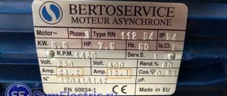
Namely, a circular woodworking machine TsA-2A-1, it uses a two-speed asynchronous motor 4AM100L8/4U3. Its main parameters are first speed (triangle) 700 rpm, current 5.0 A, power 1.4 kW, stars - 1410 rpm, current 5.0 A, power 2.4 kW.
I was asked to make several speeds, for different wood and for different sharpness of the circular saw. But alas, you can’t do this without a frequency converter.
Another old man is a special-design lathe UT16P, it has an engine of 720/1440 rpm, 8.9/11 A, 3.2/5.3 kW:
Nameplate of two-speed electric motor 11 kW lathe
Switching is also done with a switch, and the machine diagram looks like this:
electrical diagram of a lathe
There is an error in this diagram, exactly on the topic of the article. Firstly, speed switching is carried out not by relay P2, but by switch B2. And secondly (and most importantly) – the switching diagram absolutely does not correspond to reality. And she confused me, I tried to connect using it. Until I created this diagram:
Real circuit diagram for switching on a two-speed motor of a UT16P lathe
Additionally - the appearance and location of the electrical circuit elements.
lathe diagram - appearance
electrical diagram of a lathe - arrangement of elements
That's all.
Friends! Anyone who comes across such machines and engines, write, share your experience, ask questions, I will be glad!
Update March 2017
I am posting photos and diagrams of the practical activation of a two-speed electric motor.
The engine runs on hydraulic power. At reduced speed, it produces low pressure, allowing hydraulically driven machinery to be controlled more accurately. At increased speed, the pressure increases approximately 2 times, and the speed of movement accordingly.
Borno two-speed motor - 6 wires come to the terminals
Two-speed motor diagram
Two-speed hydraulic motor
Two-speed motor contactors. The left one engages in a triangle (low speed), the right ones – a double star
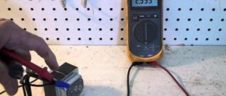
Automatic motors. It can be seen that the delta current is up to 8A, the star current is up to 13A
Wiring diagram for the power part of the Dahlander engine.
Connection diagram for the control part of a two-speed Dahlander engine.
Briefly about the Dahlander engine switching diagram.
The engine is switched on via a time relay with a shutdown delay.
I wrote in detail about the time relay here.
The 215A2 time relay turns on immediately and turns off after 5 seconds. This is necessary so that the engine and contactors are not jerked over trifles, and short-term stops of hydraulic movements do not turn off the hydraulic station engine.
Next, relay 261K0 switches on the triangle operating mode, relay 261K1 switches on the star mode.
Video of engine operation according to Dahlander's scheme
Unfortunately, there is no video in Russian on this topic.
Control diagram for the stand shown above:
Another diagram, switching speeds - through Stop:
Sharpening machine on Dahlander engine
I recently came across a machine with a two-speed motor, I am posting its diagram.
Scheme of a sharpening machine on a two-speed Dahlander motor
I am often asked what kind of protection should be given to this engine? Here, in the diagram, is a simple thermal relay (PT1), configured for a higher current (about 11 A).
Here is the engine nameplate:
Parameters of two-speed sharpening machine motor
And here are his pin designations:
Two-speed motor terminals
Why do you think the rectangle PS (speed switch) is shown instead of the connection diagram? That's right, the circuit would then be 2 times larger and more complex.
Schemes for the article in the SPlan program
• 2-speed motor / Schemes for the article https://www.samelectric.ru/promyshlennoe-2/podklyuchenie-dvuhskorostnogo-asinhronnogo-dvigatelya.html, zip, 14.44 kB, downloaded: 865 times./
Did you like the article? Add it to your social network and rate it!
(21 ratings, average: 5.00 out of 5)
Practical implementation
In practice, I only came across circuits on PKP-25-2 switches. This is a universal miracle of Soviet switching, which can have a million possible combinations of contacts. There is a cam inside (there are also several variations in shape) that can be rearranged.
This is a real puzzle and rebus that requires high concentration of consciousness. It’s good that each contact is visible through a small slot, and you can see when it is closed or open. In addition, contacts can be cleaned through these slots in the housing.
There can be several positions, their number is limited by the stops shown in the photo:
Batch switch PKP-25-2
PKP switch 25. A puzzle for everyone.
Batch switch PKP-25-2 - contacts
Practical implementation of a two-speed electric motor connection diagram
In practice, I only came across circuits on PKP-25-2 switches. This is a universal miracle of Soviet switching, which can have a million possible combinations of contacts. There is a cam inside (there are also several variations in shape) that can be rearranged.
This is a real puzzle and rebus that requires high concentration of consciousness. It’s good that each contact is visible through a small slot, and you can see when it is closed or open. In addition, contacts can be cleaned through these slots in the housing.
There can be several positions, their number is limited by the stops shown in the photo:
Batch switch PKP-25-2
PKP switch 25. A puzzle for everyone.
Batch switch PKP-25-2 – contacts
Practical use
As I already said, I came across such engines in Soviet machines that I restored.
Namely, the circular woodworking machine TsA-2A-1, which uses a two-speed asynchronous motor 4AM100L8/4U3. Its main parameters are first speed (triangle) 700 rpm, current 5.0 A, power 1.4 kW, stars - 1410 rpm, current 5.0 A, power 2.4 kW.
I was asked to make several speeds, for different wood and for different sharpness of the circular saw. But alas, you can’t do this without a frequency converter.
Another old man is a special-design lathe UT16P, it has an engine of 720/1440 rpm, 8.9/11 A, 3.2/5.3 kW:
Nameplate of two-speed electric motor 11 kW lathe
Switching is also done with a switch, and the machine diagram looks like this:
electrical diagram of a lathe
There is an error in this diagram, exactly on the topic of the article. Firstly, speed switching is carried out not by relay P2, but by switch B2. And second (and most importantly) - the switching diagram absolutely does not correspond to reality. And she confused me, I tried to connect using it. Until I created this diagram:
Real circuit diagram for switching on a two-speed motor of a UT16P lathe
Additionally, the appearance and location of the electrical circuit elements.
Typical control circuits for an inferno with a squirrel-cage rotor
Motors of this type of low and medium power are usually started by direct connection to the network without limitation of starting currents. In these cases, they are controlled using magnetic starters, which at the same time provide some types of their protection.
The control circuit for an asynchronous motor using a magnetic starter (Fig. 2.1) includes a magnetic starter consisting of a KM
and three built-in thermal protection relays
KK.
The circuit provides direct (without current and torque limitation) starting of the motor, disconnecting it from the network, as well as protection against short circuits (
F A fuses)
and overload (KK thermal relays
).
Rice. 2.1. Blood pressure control scheme using
irreversible magnetic starter
To start the engine, close the QF
and press the start button
S B
1
.
KM
contactor receives power which, when turned on, connects it to the power source with its main power contacts in the motor stator circuit, and bypasses the
S B1 button with its auxiliary contact.
The engine takes off according to its natural characteristics.
To turn off the engine, the stop button S B2 is pressed,
KM
contactor loses power and disconnects the engine from the network. The process of engine braking by coasting begins under the influence of the load torque on its shaft.
Catalog
The catalog contains the technical characteristics of asynchronous three-phase two-speed electric motors AIR with a squirrel-cage rotor produced in Belarus. The parameters of 2-speed motors from other manufacturers may differ slightly.
| Type | Technical characteristics of two-speed motors | Weight, kg | |||||||
| R, kW | Rotation speed, rpm | Efficiency, % | cos f | Iп/Iн | Mn/Mn | Mmax/Mn | Mmin/Mn | ||
| AIR63A4/2 | 0,19 | 1380 | 55,0 | 0,66 | 3,5 | 1,6 | 1,8 | 1,0 | 5,1 |
| 0,265 | 2640 | 61,0 | 0,75 | 4,0 | 1,2 | 1,8 | 0,8 | ||
| AIR63V4/2 | 0,265 | 1350 | 57,0 | 0,68 | 3,5 | 1,6 | 2,0 | 1,0 | 6,0 |
| 0,37 | 2580 | 61,0 | 0,82 | 4,0 | 1,2 | 1,7 | 0,8 | ||
| AIR71A4/2 | 0,48 | 1360 | 69,0 | 0,76 | 4,5 | 1,5 | 1,9 | 1,4 | 8,6 |
| 0,62 | 2780 | 68,0 | 0,85 | 4,5 | 1,5 | 1,9 | 1,3 | ||
| AIR71V4/2 | 0,71 | 1360 | 69,0 | 0,84 | 4,5 | 1,75 | 1,9 | 1,5 | 9,4 |
| 0,85 | 2780 | 68,0 | 0,86 | 4,5 | 1,85 | 2,0 | 1,4 | ||
| AIR80A4/2 | 1,12 | 1410 | 74,0 | 0,78 | 5,0 | 1,9 | 2,2 | 1,6 | 13,0 |
| 1,50 | 2730 | 73,0 | 0,85 | 5,0 | 1,9 | 2,0 | 1,5 | ||
| AIR80V4/2 | 1,50 | 1380 | 75,0 | 0,75 | 5,0 | 2,0 | 2,0 | 1,6 | 15,0 |
| 2,00 | 2720 | 75,0 | 0,84 | 5,0 | 2,0 | 2,1 | 1,6 | ||
| AIR90L4/2 | 2,20 | 1430 | 79,0 | 0,83 | 6,0 | 1,9 | 2,4 | 1,6 | 19,7 |
| 2,65 | 2850 | 76,0 | 0,82 | 6,0 | 2,0 | 2,4 | 1,5 | ||
| AIR90L6/4 | 1,32 | 930 | 74,0 | 0,68 | 5,0 | 1,6 | 1,9 | 1,5 | 19,6 |
| 1,60 | 1430 | 74,0 | 0,85 | 5,5 | 1,6 | 2,1 | 1,2 | ||
| AIR90L8/4 | 0,80 | 710 | 62,0 | 0,60 | 3,0 | 1,7 | 2,0 | 1,6 | 19,0 |
| 1,32 | 1410 | 75,0 | 0,86 | 5,0 | 1,5 | 2,0 | 1,3 | ||
| AIR100S4/2 | 3,00 | 1430 | 82,0 | 0,84 | 5,5 | 2,1 | 2,4 | 1,6 | 24,2 |
| 3,75 | 2790 | 80,0 | 0,90 | 5,5 | 2,0 | 2,4 | 1,6 | ||
| AIR100L4/2 | 4,00 | 1400 | 82,0 | 0,88 | 5,5 | 1,9 | 2,1 | 1,6 | 29,2 |
| 4,75 | 2820 | 82,0 | 0,91 | 6,0 | 2,2 | 2,4 | 1,6 | ||
| AIR100S6/4 | 1,70 | 940 | 76,0 | 0,76 | 4,5 | 1,3 | 1,8 | 1,3 | 22,5 |
| 2,24 | 1400 | 80,0 | 0,86 | 5,5 | 1,3 | 1,9 | 1,2 | ||
| AIR100L6/4 | 2,12 | 950 | 77,0 | 0,73 | 4,5 | 1,4 | 2,0 | 1,3 | 27,1 |
| 3,15 | 1430 | 80,0 | 0,86 | 5,5 | 1,5 | 2,1 | 1,4 | ||
| AIR100S8/4 | 1,00 | 720 | 70,0 | 0,61 | 4,0 | 1,2 | 1,8 | 1,1 | 21,5 |
| 1,70 | 1430 | 79,0 | 0,87 | 5,0 | 1,1 | 1,8 | 1,0 | ||
| AIR100L8/4 | 1,40 | 720 | 72,0 | 0,60 | 4,0 | 1,6 | 2,0 | 1,5 | 26,2 |
| 2,36 | 1430 | 81,0 | 0,89 | 5,5 | 1,4 | 1,9 | 1,0 | ||
| AIR100S8/6 | 1,00 | 710 | 72,0 | 0,64 | 5,0 | 1,4 | 2,0 | 1,3 | 22,0 |
| 1,25 | 970 | 77,0 | 0,66 | 5,5 | 1,5 | 2,2 | 1,0 | ||
| AIR100L8/6 | 1,32 | 710 | 71,0 | 0,66 | 4,0 | 1,6 | 1,9 | 1,4 | 26,0 |
| 1,80 | 960 | 76,0 | 0,73 | 5,0 | 1,4 | 2,0 | 0,9 | ||
| AIR112M8/4 | 2,2 | 710 | 70,0 | 0,65 | 5,0 | 1,2 | 1,8 | 1,0 | 38,6 |
| 3,6 | 1420 | 77,0 | 0,88 | 6,0 | 1,2 | 1,6 | 1,0 | ||
| AIR160S4/2 | 11,0 | 1460 | 89,5 | 0,84 | 7,0 | 1,6 | 2,9 | 1,6 | 99,8 |
| 14,0 | 2790 | 85,5 | 0,90 | 7,0 | 1,6 | 2,9 | 1,0 | ||
| AIR160M4/2 | 14,0 | 1460 | 89,5 | 0,86 | 7,0 | 1,5 | 2,9 | 1,5 | 103,9 |
| 17,0 | 2930 | 86,5 | 0,91 | 7,0 | 1,6 | 2,9 | 1,0 | ||
| AIR160S6/4 | 7,5 | 980 | 86,5 | 0,78 | 6,5 | 1,8 | 2,8 | 1,7 | 88,9 |
| 8,5 | 1460 | 87,5 | 0,90 | 6,0 | 1,5 | 2,2 | 1,3 | ||
| AIR160M6/4 | 11,0 | 980 | 87,5 | 0,79 | 6.5 | 1,7 | 2,8 | 1,7 | 113,9 |
| 13,0 | 1460 | 88,0 | 0,91 | 6,0 | 1,4 | 2,1 | 1,4 | ||
| AIR160S8/4 | 6,0 | 730 | 81,0 | 0,69 | 5,5 | 1,8 | 2,0 | 1,0 | 86,9 |
| 9,0 | 1460 | 84,0 | 0,88 | 7,0 | 1,5 | 2,0 | 0,8 | ||
| AIR160M8/4 | 9,0 | 730 | 81,5 | 0,71 | 5,5 | 1,5 | 2,0 | 1,0 | 108,9 |
| 13,0 | 1460 | 84,0 | 0,89 | 7,0 | 1,5 | 2,0 | 0,8 | ||
Two-speed motors from storage or on order
| Two-speed electric motor | Power | Two rotation speeds | Two-speed electric motor | Power | Two rotation speeds |
| AIR132S4/2 | 6,0/7,1 | 1455/2900 | AIR200M6/4 | 20,0/22,0 | 1000/1500 |
| AIR132M4/2 | 8,5/9,5 | 1455/2925 | AIR200L6/4 | 24,0/27,0 | 1000/1500 |
| AIR132S6/4 | 5,0/5,5 | 965/1435 | AIR200M8/4 | 15,0/22,0 | 750/1500 |
| AIR132M6/4 | 6,7/7,5 | 970/1440 | AIR200L8/4 | 17,0/24,0 | 750/1500 |
| AIR132S8/4 | 3,6/5,0 | 715/1435 | AIR200M8/6 | 15,0/18,5 | 750/1000 |
| AIR132M8/6 | 4,5/5,5 | 720/970 | AIR200L8/6 | 18,5/23,0 | 750/1000 |
| AIR132M8/4 | 4,7/7,5 | 715/1440 | AIR200M12/6 | 8,0/15,0 | 500/1000 |
| AIR132S8/6 | 3,2/4,0 | 725/965 | AIR200L12/6 | 10,0/18,5 | 500/1000 |
| AIR160S8/6 | 7,5/8,5 | 750/1000 | AIR225M4/2 | 42,0/48,0 | 1500/3000 |
| AIR160M8/6 | 11,0/13,0 | 750/1000 | AIR225M8/4 | 23,0/34,0 | 750/1500 |
| AIR160S12/6 | 3,5/7,1 | 500/1000 | AIR225M12/6 | 14,0/25,0 | 500/1000 |
| AIR160M12/6 | 4,5/10,0 | 500/1000 | AIR225M8/6 | 22,0/30,0 | 750/1000 |
| AIR180S4/2 | 17,0/20,0 | 1500/3000 | AIR250S4/2 | 55,0/60,0 | 1500/3000 |
| AIR180M4/2 | 22,0/26,0 | 1500/3000 | AIR250M4/2 | 66,0/80,0 | 1500/3000 |
| AIR180M6/4 | 15,0/17,0 | 1000/1500 | AIR250S8/4 | 33,0/47,0 | 750/1500 |
| AIR180M8/4 | 13,0/18,5 | 750/1500 | AIR250M8/4 | 37,0/55,0 | 750/1500 |
| AIR180M8/6 | 11,0/15,0 | 750/1000 | AIR250S8/6 | 30,0/37,0 | 750/1000 |
| AIR180M12/6 | 7,0/13,0 | 500/1000 | AIR250M8/6 | 45,0/55,0 | 750/1000 |
| AIR180M12/4 | 3,7/11,0 | 500/1500 | AIR250S12/6 | 16,0/30,0 | 500/1000 |
| AIR200M4/2 | 27,0/35,0 | 1500/3000 | AIR250M12/6 | 18,5/36 | 500/1000 |
| AIR200L4/2 | 30,0/38,0 | 1500/3000 | 5AM250M12/6 | 18,5/36 | 500/1000 |
Two-speed AIS motors | DIN Standard AIS to replace imported multi-speed motors
To replace a European two-speed electric motor with a new domestic one with a lower price and delivery time, select the model from the table and call the Quality Systems specialists. You may also find the AIS Single Speed Motors Catalog useful
| Marking | Power | Rotation frequency | Marking | Power | Rotation frequency |
| AIS71A4/2 | 0,19/0,265 | 1380/2640 | AIS100LA6/4 | 1,32/1,60 | 930/1420 |
| AIS71B4/2 | 0,265/0,37 | 1350/2580 | AIS100LA8/4 | 0,80/1,32 | 700/1400 |
| AIS80A4/2 | 0,48/0,62 | 1360/2780 | AIS112M4/2 | 4,00/4,75 | 1400/2820 |
| AIS80V4/2 | 0,71/0,85 | 1360/2780 | AIS112M6/4 | 2,12/3,15 | 940/1420 |
| AIS90S4/2 | 1,12/1,5 | 1410/2730 | AIS112M8/4 | 1,40/2,36 | 720/1420 |
| AIS90L4/2 | 1,50/2 | 1380/2730 | AIS112M8/6 | 1,32/1,8 | 710/950 |
| AIS90L8/4 | 0,18/0,37 | 710/1200 | AIS132M4/2 | 4,20/530 | 1450/2860 |
| AIS100LA4/2 | 2,20/2,65 | 1420/2850 | AIS132S8/4 | 2,20/3,60 | 710/1420 |
Device and design
Structurally, two-speed electric motors differ from standard ones; they have a special stator design, and the rotor is a regular squirrel-cage motor.
The most common types of design of two-winding electric motors: The design of two-speed electric motors with two dependent windings may differ based on the ratio of the number of poles - 1:2, 3:2, 4:3. With a rotation speed ratio of 1:2, one pole-switching stator winding is used according to the Dahlander circuit. At ratios 3:2, 4:3 - one pole-switching winding using the amplitude-phase modulation method.
When using dependent windings, 2-speed electric motors are manufactured in standard dimensions, while independent ones have slightly larger dimensions.
It is worth paying attention that the AIR two-speed electric motor will produce different power at each rotation speed. Also, when using frequency converters, the power remains unchanged. Most general industrial drives, according to the operating manual, do not provide for operation with frequency converters. Frequency converters can reduce the rated life by several times or damage the equipment