Methods for determining the winding terminals of three-phase motors
In No. 3 for 98, reader V.I.
Bondarenko asks how to determine the “beginning” and “end” of the windings of a 3-phase electric motor? The editors' answer was also given there that with the help of a battery and a light bulb you can determine the terminals belonging to the winding of the same name. But it does not fully answer the question posed. “Start” and “end” are determined by one of the following methods. So, after determining the terminals with the simplest probe from a battery and a light bulb, each pair of terminals belonging to individual phase windings is marked in some way and the determination of “beginning” and “end” begins.
Transformation method
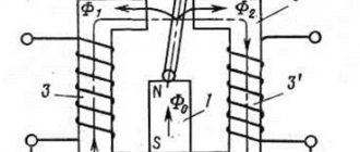
The transformation method is that a test lamp or 60-90 V voltmeter is connected to one of the phase windings (winding III in Fig. 1, a, b), and the other two are connected in series and connected to a 220 V network. Test lamp ( CL) will light up if the end of one of the phase windings is connected to the beginning of the other (at point O). In this case, their total magnetic flux is summed up and induces an EMF in the third phase winding, which will cause the lamp to glow or the voltmeter needle to deflect (Fig. 1a).
If the control lamp does not light up, there are two “ends” or two “beginnings” at the common point of the connected phase windings. In this case, the magnetic fluxes cancel each other (Fig. 1, b), therefore, there is no EMF in the third winding - the lamp does not light up, the voltmeter needle does not deviate. The terminals of one of the phase windings are swapped and the circuit is turned on again.
If a lamp or voltmeter detects the presence of voltage in the third winding, then the output of one of the windings connected at point O is marked as “end”, the output of the other as “beginning”.
Then assemble the circuit shown in Fig. 1, c. The lamp (or voltmeter) is connected to one of the two windings with already matched leads and the beginning and end of the third winding are determined, as described above.
Dialing method
The ohmmeter diagnostic method will help with the question of how to check the power transformer. The resistance between the terminals of one winding begins to ring. This is how the integrity of the conductor is established. Before this, the housing is inspected for the absence of deposits and deposits as a result of heating of the equipment.
Next, the current values in Ohms are measured and compared with the passport values. If there are none, then additional diagnostics under voltage will be required. It is recommended to ring each terminal relative to the metal body of the device where the ground is connected.
Read also: Repairing the barrel of a Makita 2450 rotary hammer
Before taking measurements, all ends of the transformer should be disconnected. It is recommended to disconnect them from the circuit for your own safety. They also check for the presence of an electronic circuit, which is often present in modern power models. It should also be desoldered before testing.
Infinite resistance speaks of complete isolation. Values of several kilo-ohms already raise suspicions about a breakdown in the housing. This may also be due to accumulated dirt, dust or moisture in the air gaps of the device.
Pin selection method
The pin selection method is convenient to use when determining the “beginnings” and “ends” of motors with power up to 3.5 kW. To implement it, neither a lamp nor a voltmeter is needed, which is most acceptable for V.I. Bondarenko, since he lives in a village where it is probably difficult to find a voltmeter.
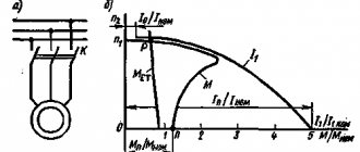
One terminal from each winding is connected to a common point, and the other terminals are connected to a three-phase network corresponding to the rated voltage of the electric motor in a star circuit (Fig. 2a). If all three “beginnings” or “ends” are at a common point (this does not matter for the operation of the electric motor, since “beginning” and “end” are very conventional designations), then the electric motor will operate normally. Then the conclusions connected to the network are marked, for example, as “ends”, and the conclusions combined into a common point as “beginning” (Fig. 2.6).
If, for example, there are two “beginnings” and one “end” at a common point (Fig. 2, c), then the electric motor hums strainedly, its rotor does not immediately move and rotates poorly. In this case, you should not leave the engine on for a long time (more than 2.3 s). It is necessary to turn it off as quickly as possible and change the terminals of one of the windings. If this time the engine does not work, then the terminals of this winding are returned to their original place and the terminals of the next winding are swapped. The maximum number of samples with this method is only three.
Electric motor winding terminals - connection diagrams
Designation of stator winding terminals
Each stator of a three-phase electric motor has three coil groups (windings) - one for each phase, and each coil group has 2 terminals - the beginning and end of the winding, i.e. There are only 6 pins that are signed as follows:
- C1 (U1) is the beginning of the first winding, C4 (U2) is the end of the first winding.
- C2 (V1) is the beginning of the second winding, C5 (V2) is the end of the second winding.
- C3 (W1) is the beginning of the third winding, C6 (W2) is the end of the third winding.
Conventionally, in the diagrams, each winding is depicted as follows:
The beginnings and ends of the windings are brought out into the terminal box of the electric motor in the following order:
Depending on the connection of these terminals, such parameters of the electric motor as the supply voltage and the rated stator current change. which circuit to use to connect the electric motor windings from the passport data.
The main winding connection diagrams are triangle (denoted by Δ) and star (denoted by Y), which we will analyze in this article.
Note: In the terminal box of some electric motors you can only see three terminals - this means that the motor windings are already connected inside its stator. As a rule, the windings inside the stator are connected when repairing an electric motor (if the factory windings are burned out). In such motors, the windings are usually connected in a star configuration and are designed for connection to a 380 Volt network. To connect such a motor, you simply need to supply three phases to its three outputs.
Connection diagram of electric motor windings according to the “triangle” diagram
To connect the windings of an electric motor according to the “triangle” diagram, it is necessary: connect the end of the first winding (C4/U2) to the beginning of the second (C2/V1), the end of the second (C5/V2) to the beginning of the third (C3/W1), and the end of the third windings (C6/W2) - with the beginning of the first (C1/U1).
Conventionally, this is depicted in the diagram as follows:
Voltage is applied to terminals “A”, “B” and “C”.
In the terminal box of the electric motor, the connection of the windings according to the “triangle” diagram has the following form:
A, B, C—connection points for the power cable.
Connection diagram of electric motor windings according to the “star” scheme
To connect the windings of an electric motor in a star configuration, it is necessary to connect the ends of the windings (C4/U2, C5/V2 and C6/W2) to a common point, while voltage is applied to the beginnings of the windings (C1/U1, C2/V1 and C3/W1 ).
Conventionally, this is depicted in the diagram as follows:
In the terminal box of the electric motor, the star connection of the windings has the following form:
Definition of winding terminals
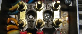
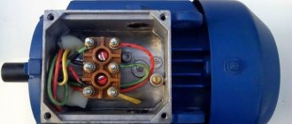
Sometimes situations arise when, after removing the cover from the terminal box of an electric motor, you are horrified to discover the following picture:
In this case, the winding terminals are not labeled, what should I do? Don't panic, this issue can be completely resolved.
The first thing to do is to divide the leads into pairs, each pair should have leads related to one winding, this is very easy to do, we will need a tester or a two-pole voltage indicator.
If using a tester, set its switch to the resistance measurement position (underlined by a red line); when using a bipolar voltage indicator, before use, it is necessary to touch the live parts under voltage for 5-10 seconds to charge it and check its functionality.
Next, you need to take any one terminal of the winding, conditionally take it as the beginning of the first winding and accordingly sign it “U1”, then touch the “U1” terminal we signed with one tester or voltage indicator probe, and touch with the second probe any other terminal from the remaining five unsigned ends. If, having touched the second terminal with the second probe, the tester readings have not changed (the tester shows one) or in the case of the voltage indicator - not a single light comes on - we leave this end and touch the other terminal of the remaining four ends with the second probe, and touch the ends with the second probe to until the tester readings change, or, in the case of a voltage indicator, until the “Test” light comes on. Having found the second terminal of our winding in this way, we accept it conditionally as the end of the first winding and sign it “U2” accordingly.
Open triangle method
The windings are connected according to the diagram shown in Fig. 3. If the “beginning” and “end” meet at points A and B, the voltmeter will show the same voltage on each winding. When one of the windings is “inverted,” the voltage on it will be slightly higher than on the other two.
In conclusion, I would like to remind you that the following designations are accepted for three-phase electric motors: the conventional “beginnings” are designated C1, C2, C3, and the corresponding “ends” are C4, C5, C6.
The terminals of low-power electric motors are marked with paint: the first winding is yellow, the second is green, the third is red. Moreover, the “ends” of each winding are additionally marked with black paint according to the main color.
Source: www.mastertip.ru
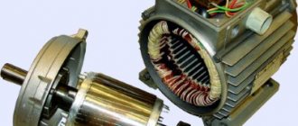
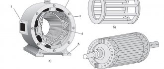
Single-phase motors are low-power electrical machines. The magnetic circuit of single-phase motors contains a two-phase winding, consisting of a main winding and a starting winding.
Two windings are needed to cause the rotor of a single-phase motor to rotate. The most common motors of this type can be divided into two groups: single-phase motors with a starting winding and motors with a running capacitor.
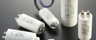
For engines of the first type, the starting winding is switched on through a capacitor only at the time of start-up and after the engine has developed a normal rotation speed, it is disconnected from the network. The motor continues to operate with one working winding. The size of the capacitor is usually indicated on the motor nameplate and depends on its design.
For single-phase asynchronous AC motors with a running capacitor, the auxiliary winding is permanently connected through a capacitor. The value of the working capacitance of the capacitor is determined by the design of the engine.
Asynchronous motor control
Direct connection to mains power
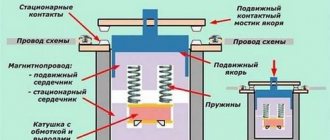
The use of magnetic starters allows you to control asynchronous electric motors by directly connecting the motor to an alternating current network.
Using magnetic starters you can implement the following circuit:
The use of a thermal relay makes it possible to protect the electric motor from current values much higher than the rated value.
Non-reversible circuit
Reversible circuit
The disadvantage of direct commutation of the windings of an asynchronous electric motor with the network is the presence of large starting currents when starting the electric motor.
Smooth start of an asynchronous electric motor
In tasks where it is not necessary to adjust the speed of the electric motor during operation, a soft starter is used to reduce starting currents.
Connecting a three-phase motor.
Diary entry created by Serj, 02/06/14 .345
Connection Every asynchronous three-phase motor is designed for two rated voltages of a three-phase network 380/220 - 220/127, etc. The most common are 380/220V motors. Switching the motor from one voltage to another is done by connecting the windings “star” - for 380 V or to “delta” - for 220 V. If the engine has a connection block that has 6 terminals with installed jumpers, you should pay attention to the order in which the jumpers are installed . If the engine does not have a block and has 6 leads, they are usually collected in bundles of 3 leads. The beginnings of the windings are collected in one bundle, and the ends in the other (the beginnings of the windings are indicated by a dot in the diagram).
In this case, “beginning” and “end” are conditional concepts, it is only important that the directions of the windings coincide, i.e., in the example of a “star”, the zero point can be both the beginning and the ends of the windings, and in a “triangle” the windings must be connected in series, i.e. the end of one to the beginning of the next. To correctly connect to a “triangle”, you need to determine the terminals of each winding, arrange them in pairs and connect them in sequence. diagram:
If you expand this diagram, you will see that the coils are connected in a “triangle”.
If the motor has only 3 terminals, you should disassemble the motor: remove the cover from the block side and find the connection of three winding wires in the windings (all other wires are connected in 2). The connection of the three wires is the zero point of the star. These 3 wires should be broken, the lead wires soldered to them and combined into one bundle. Thus, we already have 6 wires that need to be connected in a triangle pattern.
Method for determining the beginnings and ends of the windings of a three-phase asynchronous motor
First you need to define the windings. To do this, the windings are tested with an ohmmeter and collected into conventional bundles of 3 pieces. A battery is connected to the terminals of one of the windings (for example A1-A2), and a dial voltmeter is connected to the terminals of the other winding (B1, B2) (a digital multimeter will not work - it is too inert). (see diagram [1] below) At the moment the contact of winding A with the battery is broken, the voltmeter needle will swing to some point. side. We leave the battery on the same winding (maintaining the polarity), and connect the voltmeter to the next winding - C. By changing the polarity of winding C (switching the winding leads), we achieve a deflection of the voltmeter in the same direction as in the previous case.
Thus (see diagram 1), when the contact of winding A with the battery is broken, the voltmeter, being connected to winding B and connected to winding C, should swing the arrow in one direction. If the arrow deviates in different directions, swap (arranged in different bundles) pins B1 and B2 or C1 and C2.
How to determine the beginning and end of a winding in a motor.
In this article I will tell you a way to determine the beginning and end of the winding in an asynchronous three-phase motor.
When might you need this material? Only if you have six wires of the same color in the box and there are no markings on them. Or your motor was connected in delta and you want to be able to connect it in star. I wrote how to do this here. To make it easier to explain the material, let’s first go through the accepted markings of motor winding terminals.
First way
We will need a regular 4.5 V coin cell battery and a combination meter (tester) or DC milliammeter. We first checked the windings with an ohmmeter. We have several pairs of wires, but we need to determine where these pairs have the beginning of the winding and where the end is.
Schematic diagram of a triangle connection.
We take any pair of wires belonging to one of the windings. Conventionally, we mark one of the winding terminals as the beginning (H), and the second as the end (K). We connect the tester at the limit of one or tens of milliamps of direct current to any other pair of wires belonging to a different winding.
We connect the negative battery to our conditional end (K) of the first winding. Touching the beginning of the first winding several times with the plus of the battery, we observe the tester readings. We are interested in the deflection of the instrument needle at the moment of closing the “battery - winding” circuit.
If the arrow of the device deviates to the minus, then we switch the polarity of connecting the device to the second winding and again short the battery to the first winding several times.
Now the deviations of the device at the moment of closure should be in the positive direction. The winding terminal that is connected to the plus of the tester will be the beginning of the second winding, and the minus will be the end. In the same way we determine the beginnings of all other windings.
Second way
Scheme for determining the beginnings and ends of winding phases.
We connect any two “found” phase windings in series and connect 220 V to the resulting free ends, and connect a test lamp to the remaining third winding and briefly apply 220 V. We remember how the lamp lights up.
Now we change the connection of the windings that are connected in series, that is, we swap the ends of the second winding and again supply power. The light bulb should light up differently, either brighter or weaker. If it lights up brighter, then our windings are connected in series, in the order beginning - end - beginning - end. So we sign them. We already clearly know two windings.
Now we connect any of the known ones to the unknown one and again we supply 220 V to this pair, and a lamp to the free one. Turn on the power again. Now you can immediately see from the brightness of the filament how the windings are turned on. We apply the appropriate inscriptions.
In the example given, you can use a voltmeter instead of a control light and navigate by the deflection of the arrow of the device. Now, depending on the connection diagram, you need to connect the windings. To connect with a star, we connect any three (be it the beginning or the ends) together, and the remaining three will be supplied with 380 V power . To switch to a triangle, you will need to do other manipulations.
Source: fazaa.ru
Accuracy of determining the beginnings and ends of the stator winding
At the end of the work, it is recommended to check the accuracy of the results obtained, for this:
- we connect the windings accordingly - “star” or “delta”, depending on the engine model;
- connect the engine without load;
- if necessary, adjust the direction of rotation of the shaft (swap the phases).
Thus, the beginning and end of the windings of a three-phase electric motor can be reliably determined without disassembling the motor.