Danger of sparks in switches, wires and twists
Almost every person is familiar with sparking and arc breakdown. If you press the light switch button in the dark, then with some probability you will be able to see a dim, short-term green flash through the plastic case. This effect is more typical of old switches.
The phenomenon is of a completely logical nature. When the light is turned on, the switch contacts move closer. At some point in time they are so close that a breakdown of the air gap occurs between them. A very small and short-lived arc lights up, which creates a flash.
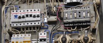
This situation is safe if we talk about a working switch. However, this often happens in junction boxes. If the wires are loosely twisted or poorly pressed under the terminal block of the machine, they will also spark. At the same time, the voltage and current in the network behave in the most unpredictable way. The problem is aggravated by the presence of capacitive and inductive consumers in the apartment.
Important! Poor contact in the twist, box or under the terminal block of the circuit breaker leads to sparking of the wiring. This, in turn, creates involuntary surges in mains voltage and current. This phenomenon can damage expensive household appliances. Especially those that contain electronic chips, processors and digital circuit boards.
Poor contact in twist
Black and white - read the instructions
It is worth mentioning the instructions, which are very detailed. It even indicates the metric dimensions of the device, although this seems like unnecessary information to me: well, there are two modules, and so everything is clear.
The addresses of the company's representative offices, the warranty period (3 years), the production date, and so on, which are required in such cases, are listed. And it describes in detail what the AFDP protects from and how to determine the area of its operation.
There's a very interesting nuance there. It turns out that if a line of sockets is assembled in a loop and somewhere in the middle of this loop a consumer with a switching power supply (for example, a TV) is connected, then all sockets located further from the AFDD will no longer be protected . Or they will, but the control tool will not be able to show it.
Consumers with switching power supplies may attenuate the signal from an arc fault. In the diagram, some of the sockets are not included in the operating area
It's all about the physics of the process. The device contains an electronic component that analyzes the nature of the sinusoidal current oscillation in the electrical network. When sparking, the sinusoid acquires an irregular shape due to the appearance of additional harmonics. The automation detects the occurrence of an arc breakdown and activates the release, which breaks the electrical circuit.
Consumers with switching power supplies (computers, televisions, digital receivers, pulse transformers for powering halogen lamps, etc.) attenuate the arc fault signal . To avoid this, it is recommended to connect such a group of consumers via a standard network extension cord with a cord length of 3-10 m.
The operating area of the AFDD has been expanded due to the connection of consumers via a standard network extension cord
Appearance and structure of the device
The wiring protection device against sparking has a design that is standard for any modular devices. The UZIS is attached to the shield using a DIN rail. On the front panel of the device there are 4 screw terminals for connecting wires:
- input phase (L in);
- input zero (N in);
- output phase (L out);
- output zero (N out).
The input is supplied with a supply voltage of 230 V. For example, from a meter or an input machine. A load is connected to the output. For example, sockets or lighting network.
Spark protection device EcoEnergy UZIS-S1-40
There is a lever on the body of the device to turn it on and off. By its position the condition of the device is judged. If the lever points to 0, it is off, if it points to 1, it is on. The protection status can also be judged by the indicator LED (light bulb). If it lights up green, then everything is fine. If it lights up or blinks red, the protection device has turned off. A detailed explanation of the light bulb luminescence values is available on the device body.
Next to the lever there is a small adjuster for a screwdriver (twist). It allows you to set the voltage value at which the AFIS will automatically turn off. That is, this device can protect the network not only from sparking, but also from overvoltage.
Spark protection device UZIS-S1-40
Sparking wiring is the most common cause of fires. Sparking can occur at the connection points of wires (twists, loose contacts, mechanical damage to the wire) and is not noticeable until the heating of the wires leads to a fire. The UZIS-S1-40 device is capable of detecting sparks and turning off electricity. In addition, the same device protects electrical appliances from increased voltage in the network, which can arise, for example, due to a break or “burnout” of the neutral wire.
The kit includes a special plug-spark emulator to check the functionality of the device, instructions, and a sticker with a status indication table.
The device is installed in the apartment panel after the introductory RCD or automatic circuit breaker. It is capable of switching current up to 40 amperes.
Mechanical indication shows switching on (red) and switching off (green) of the device. A two-color LED displays the device status. The regulator allows you to set the level of overvoltage protection from 260 to 290 volts.
To monitor the operation of the spark protection, you can connect a red test plug to any socket protected by an AFIS. The device will immediately turn off the electricity and its indicator will turn red.
To test the protection against real sparking, I used an electric kettle and an extension cord, which I wrote about a year ago (in this extension cord, the wire is simply screwed to the contacts and dangles).
After a few seconds of sparking, the device triggered and disconnected the load.
To test the surge protection, I used LATR and an accurate multimeter.
At a voltage of 259 volts (when the threshold is set to 260 V), a shutdown occurred, and after shutdown, the indicator shows whether the voltage remains dangerously high (flashing red) or has dropped (flashing green).
The device itself consumes 0.33 W, that is, in a year it will consume only 2.89 kWh of electricity.
I filmed my experiments. As far as I know, the United States passed a law obliging all homeowners to install such a device, and after the adoption of this law, the number of fires decreased by half.
UZIS-S1-40 costs 4,500 rubles. Of course, this is not cheap, but the damage from a fire or failure of equipment due to increased voltage in the network can be many times greater, so I believe that such a device, together with an RCD or automatic circuit breaker, should be installed in every apartment or private house.
upd.: I wrote to the manufacturer and received a response regarding the differences from the Meander UZDP:
“Yes, of course we know about this device and have tested different versions of it many times. (There were several). We have made the entire set of test benches in accordance with the GOST IEC-62606-2016 standard. So the Meandrovsky UZDP never worked in accordance with the standard. In addition, in principle it does not comply with the standard, as an example: the standard implies the presence of a free release mechanism, i.e. mechanical shutdown, but there is only electrical shutdown; moreover, their algorithm includes the possibility of independent restart, and the standard categorically prohibits this! According to the standard, the device should operate from 2.5A, their data sheet says that the device recognizes sparking from 5A, etc. Read different forums, it’s the same thing everywhere - constant false positives...”
© 2021, Alexey Nadezhin
Operating principle of the AFDP
The arc flash protection device is similar in principle to an ordinary voltage relay. The device continuously monitors the shape, amplitude and direction of the mains voltage. The status of these parameters is monitored by the AFDC controller.
If sparking occurs in the network, the monitored parameters change dramatically. The controller records this event and gives a command to disconnect the relay contacts. At the same moment, the control pulse arrives at the trip lever mechanism and the device status indicator LED.
Important! Hand-held power tools (drills, grinders) are a source of network interference. During operation of these devices, normal normal sparking occurs in their brush assemblies, which can lead to false alarms of the ultrasonic device. It is recommended to power such power tools through extension cords with surge protectors.
Internal structure of the SPD
To disassemble the AFDD housing, it was necessary to drill out the flared racks.
The AFDC has been disassembled, the circuit board is visible
Printed circuit board - closer:
Printed circuit board of the AFDP, from the parts side
At the top right you can see the pads for the potentiometer (voltage relay limit switch), which is present in the Ecolight. Below are pads for connecting the controller programmer during production and a two-color LED.
The zero bus passes through the entire device from input to output, a petal is welded to it, and a blue wire is soldered to it to power the circuit.
On the top and bottom left of the board you can see the soldering of the input and output terminals. To view the board from the reverse side, you need to unsolder them.
Bent down the varistor:
Closer view of the board, view of the main chips
The inscriptions on the board are Ecolight, V1.6, RBNS758744.004.
NXP Controller:
Controller inside the AFDD
The device is quite complex, and it is not possible to put it back together:
Internal structure of the electromechanics of the SPD
A current transformer is placed on the phase wire near the input terminal. By constantly measuring current and voltage, the SPD controller monitors the state of the protected circuit. Also visible is an electromagnet that triggers the process to turn off the device when the controller so desires:
Electromagnet and transformer – execution and measurement devices
Thus, from this side there are two pairs of wires going to the board.
The coil and solenoid are closer, from a different angle
I also disassembled the control tool:
UZDP-SK control device in disassembled form
This is what an arc discharge simulator looks like:
Means for simulating sparking (arc discharge)
Features of ultrasound systems from different manufacturers
When you normally plug a plug into a socket or switch a switch key, sparking also occurs, especially if voltage is supplied to a powerful consumer of electricity. In this case, the protection device must remain switched on.
Each manufacturer of such devices solves this problem in its own way. Therefore, devices from different companies can differ noticeably in their operating algorithm and appearance. The most popular AFPD models are shown in the table.
| Device manufacturer and model | Peculiarities |
| IEK UZDP63-1 40A | Suitable for use in rooms with temperatures from -25 to +40 °C. Operating voltage range 150-280 V. |
| ABB AFDD S-ARC1 | Single-phase device, supplemented with a circuit breaker module. It is possible to connect via a comb bus and ordinary wires. Operating voltage 170-275 VAC. |
| Meander UZM 51MD | The manufacturer positions the device as a “multifunctional fire protection device.” There is an automatic restart function. The device is designed for currents up to 63 A at a voltage of 250 V (14 kW). |
Arc flash protection device UZDP63-1 63A IEK
How does a fire happen?
According to statistics, the main cause of fire in the home is electrical wiring. In the news, the cause of the fire is usually simply stated as a short circuit. At the same time, journalists do not understand the essence of this term at all. This means that the cause of the fire is a faulty electrical wiring.
But let's take a closer look at what could be the cause of unhappiness. I see three main groups of causes of electrical fires:
- Overload due to overpower or short circuit. A fire may occur if the “circuit breaker/wire” pair is incorrectly selected. What I mean is that if you choose the correct rating of the machine and the cross-section of the wire (without saving), a fire will not occur. In case of overload, the machine will operate using thermal protection, and in case of a short circuit – by electromagnetic protection. I have written about this more than once, for example here and here.
- Sparking of electrical wiring as a result of poor contact or partial break of the electrical circuit (sequential breakdown). No circuit breaker will help here, even a correctly selected ABB, since the arc current will be less than or equal to the normal current in a given circuit.
- Sparking as a result of contact where there should not be one as a result of insulation damage or displacement of live parts of the electrical wiring (parallel breakdown). With a parallel breakdown, the current in the circuit may be greater than the normal current, but there is a high probability that the duration and level of the breakdown current will not be enough to turn off the machine (incomplete short circuit). But it’s quite enough to ignite clothes near a sparking outlet!
Here are the reasons for the occurrence of sequential and parallel breakdowns, leading to a fire:
Causes of fires in electrical networks. Who will be the first to write in the comment where there is a spelling mistake in this picture?
So, devices to prevent arc breakdown (sparking) do not exist in nature. More precisely, there are only two of them:
- A man with his senses,
- Arc flash protection device with spark detection (based on load current analysis).
There is no point in relying on the senses, so the only option left is electronic spark detection (ESD).
Here is the summary table of who is capable of what:
Causes of fire and devices - who reacts to what
Let me explain briefly -
- a circuit breaker (protective circuit breaker) protects the circuit from excess current in the circuit above its nominal value and from short circuits;
- An RCD (residual current device) protects a person from direct contact with live parts. The fact of touch is determined by the increased leakage current, after which the circuit is turned off;
- The difavtomat (differential machine) contains two previous devices - a protective circuit breaker and an RCD.
As you can see, none of the listed devices can protect against sparking and, ultimately, fire. Only an AFPD can do this.
Below I will give a diagram that includes all these devices, maximally protecting the person, the electrical wiring, and the load from all troubles, including fire.
Characteristics for choosing a protection device
Devices that protect wiring from sparking have appeared on the market relatively recently. However, there is nothing new or questionable about their characteristics. The main parameters of these devices are:
- Rated voltage. The network voltage value at which the protection device is able to operate in normal mode.
- Operating voltage range. Many ultrasonic devices have a built-in voltage relay. A regulator is used to set the response thresholds.
- Maximum operating current. The total power of consumers that can be connected via AFIS depends on this parameter. In domestic conditions, devices with 16, 25, 32 and 63 A are common.
- Restart time. This option is not available on all spark protection devices. It determines how long after triggering the device will supply voltage to the network again.
- Shutdown time. This characteristic shows how long it takes the ultrasonic device to turn off after detecting a spark.
Note! In the CIS countries, UTIS is a rarely used device. In documentation from different manufacturers it appears under different names. For example, UZDP, AFCI, AFDD.
What is inside
The delivery package did not blow my mind, but it pleased me. A traditional cardboard box, in which such devices are usually sold.
In addition to the instruction manual and the device itself, the kit includes a test block made in the form factor of a plug. It serves to check the performance of the AFDD and assess the area of its operation.
Test unit made in a fork form factor
By the way, the manufacturer also included a sticker in the box with a description of the indication of the operating modes of the AFZ. It is very useful at first, since not only are there many of these modes, but the device is also new, unknown to many.
As stated in the instruction manual, the IEK® AFDD provides protection not only from arc flashover, but also from surge voltages ( varistor built-in ) and from network voltage above 275+5 V. Each emergency condition is accompanied by an indication that remains even after turning off the device (if there is power in the network).
The indication is designed so that at a glance you can recognize the reason for the operation of the AFDD. The instruction manual explains all possible operation options. Thus, a constant green light indicates normal operation of the device . A constant red signal indicates that the line has been disconnected due to an arc fault. See Table 1 for details.
Table 1 . IEK® SPD indication modes
In order not to look at the product data sheet every time the LED on the AFDD body signals something, the manufacturer has attached a sticker with a decoding. I glued it to the inside of the electrical panel door - and the cheat sheet is always at hand.
Connection diagram
Spark protection devices are connected using a simple circuit. The upper L and N contacts are intended for connecting the input power cable. The lower ones are for the weekend.
It is advisable to install a circuit breaker on the phase wire in front of the AFIS. Its rating should not exceed the operating current of the AFDD. Otherwise, the spark protection may fail during a short circuit.
It is not possible to expand the throughput capacity of an AFDC using a contactor. All current must flow through the protection device. Otherwise, it will not be able to correctly register current and voltage surges at the consumer.
Bench tests
I “drove” the AFDP a little on a laboratory bench.
Checking the operation of the AFDC using a kettle
A test on an autotransformer (LATR) showed that the AFDC stops functioning at a voltage of less than 100 V. In this case, the load remains on, but the operation indicator goes out.
The load is turned off at a voltage of 275 V, as stated. When the voltage drops, switching occurs at approximately 270 V.
The tests involved a kettle with a power of 1800 W, its current is more than 8 A.
Connecting the load to the AFDD for testing
I caused sparking by moving the plug in the loose terminals. As a result, the AFDC clearly performed its function, depending on the duration of the spark.
Real sparking and the result is shown in the video:
Method of finding a sparking place
Sparking is a harbinger of fire. Therefore, if the spark protection device constantly trips, then you need to look for the location of the unstable contact. Attention should be paid to the following nodes:
- Distribution boxes. Open, look, look for the burning smell. If you turn off the voltage in the apartment, then you can test the twists for heating.
- Sockets, extension cords, plugs. They also get hot and smoke when heated.
- Apartment distribution board. The screws on the terminals of circuit breakers are often loose. As a result, poor contact with the wires and sparking occurs. Terminal blocks on automatic machines should be periodically tightened, but without fanaticism.
Separately, the main signs of sparking contacts should be noted:
- crackling at the spark site;
- the smell of burning;
- overheating of connections;
- smoke;
- blinking light;
- crackling in the speakers of acoustic systems;
- light, sparks.
The operating principle of the AFDD is based on monitoring the state of voltage and current in the electrical wiring. Monitoring these parameters allows you to detect the appearance of sparks and arcs in strands and terminal blocks at an early stage and turn off the power supply to the apartment. As a result, the risk of wiring fires or damage to expensive consumer electronics is significantly reduced.
The arc protection device most closely resembles a voltage relay. Both protection devices have an upper and lower operating voltage limit. However, the AFDD has broader functionality, that is, it can detect sparks in twists and other unreliable burning contacts.
What is sparking and arcing?
A little theory.
Sparking is an unpredictable sudden change in current and voltage from the supply line. In this case, the current and voltage due to the reactive component in the line can take values many times higher than the nominal ones.
Scientifically speaking, sparking is also called arc breakdown . Arc breakdown can be of two types:
- Sequential arc flash. This is a breakdown as a result of poor contact in one of the conductors of the supply network. However, none of the listed devices is capable of identifying this problem, except for ultrasonics.
- Parallel arc breakdown. This is a breakdown between two poles of the electrical network. In our case, between phase and zero, or phase and ground. And if with a serial breakdown the average current in the network decreases, then with a parallel breakdown it increases. It would seem that an ordinary machine gun could help us here? But it's not that simple. The circuit breaker has a time-current characteristic, and it takes a certain time to turn off at a given current. The time before fire during such a breakdown can be very short, and the current may be insufficient for instant shutdown, and a fire will occur. This happens in fairly common cases in practice, when long thin wires come from a machine with a high rated current, and a breakdown occurs in them somewhere closer to the load.
Types of arc faults are shown in the figure:
Serial and parallel arc breakdown leading to sparking and fire
In both types of breakdown it is accompanied by light, sound and thermal effects. And this, under certain conditions, easily leads to fire.
In addition, electromagnetic interference occurs, which spreads through electrical networks and through the electromagnetic field, and causes malfunctions in the operation of various low-current equipment.
How to protect yourself in advance from such uncertain and unpleasant situations and take timely measures?
This is exactly what the article is about, this is an UIS (Spark Protection Device) . It is produced by several manufacturers and may also be called an Arc Flash Protective Device (AFD), Spark Protection Relay (ISR), or Arc Flash Protective Device (AFPD).
Download
Below I post files for downloading on this device, including the relevant GOSTs.
- 1. Listovka_UZIs_new_C1_40.pdf. Spark protection device UZIS-S1 for automatic shutdown of the sparking circuit. Leaflet.
- 2. Prezent_UZIs_new_C1_40.pdf. Presentation of Ecolight UZIS.
- 3. Imitator_iskreniya.pdf. Description of the spark simulator.
- 4. Methodicheskie_rekomendacii.pdf. Expert examination of electrical equipment contact units after a fire in order to identify signs of high transient resistances.
- 5. UZIs_instrukciya.pdf. SPARK PROTECTION DEVICE UZIS-S1-40 TU 27.12.23-001-05342780-2017 Operating manual.
- 6. Questions-otvet1.3.pdf. Questions and answers from the manufacturer of ultrasonic devices.
- 7. GOST IEC 62606-2016.pdf. GOST, on the basis of which ultrasound is produced.
- 8. Technological map for installation of ultrasonic devices.pdf. Detailed description of the process and rules for installing ultrasonic devices
- 9. UZIS Certificate TR TS.pdf. Certificate of conformity of the Customs Union for UZIS
Liked? Please rate and read other blog articles! ( 18 ratings, average: 4.94 out of 5)
