What are internal lightning protection devices intended for and how do they work during discharges?
The spontaneous occurrence of lightning occurs suddenly, creating enormous destruction.
External lightning protection, consisting of a lightning rod located above the roof, as well as a lightning rod and a grounding loop, allows you to protect your house from it.
The discharge current, penetrating as a short-term pulse through the prepared circuit, is very large. It induces overvoltage in nearby building wiring and conductive parts, which can burn insulation and damage household appliances.
Internal lightning protection devices, which are a set of technical devices and instruments based on SPD modules and connected to the grounding system, are designed to prevent the dangerous consequences of a lightning discharge.
They work reliably not only in the event of a direct lightning strike on the house, but also extinguish discharges falling into:
- power line supply;
- nearby trees and buildings;
- soil located next to the building.
If there are usually no issues with a blow to a power line, then in the last two cases the overvoltage can impulse penetrate into the home wiring along the ground circuit, water supply pipes, sewerage pipes, and other metal lines, as shown in the very first picture
The operation of internal lightning protection occurs by connecting the penetrating high-voltage pulse to a specially selected arrester or electronic element - a varistor.
It is switched on at the difference of two potentials and for normal voltage it has a very high resistance when the currents through it are limited to not exceed a few milliamps.
When an emergency pulse hits the varistor circuit, it opens the semiconductor junction, short-circuiting it. Through it, dangerous potential begins to flow to the protective grounding.
After the varistor, the dangerous voltage is significantly limited. Modern protection modules - SPDs - have been created on the basis of these electronic components.
External protection
External protection, in turn, can also be divided into two types: passive and active. Passive protection is a standard lightning rod, consisting of an air terminal, a down conductor and a grounding conductor. The principle of operation of this design is extremely simple: the lightning rod intercepts the electrical charge and redirects it through the down conductor to the ground electrode, which in turn extinguishes the charge in the ground.
House with external lightning protection
Lightning rod
The lightning rod must be installed at the highest point of the house and can have several versions:
1. Metal pin up to 1.5 meters high. It is made of copper or galvanized steel and has a diameter of at least 12 mm. In this case, the larger the diameter, the better. This design is compatible with any type of metal roofing.
2. A metal cable that is stretched along the roof at a height of at least a meter. This method is preferable for wooden and slate roofs.
3. Metal mesh of reinforcement located over the entire roof area. Suitable for absolutely any roofing materials.
An alternative location for the lightning rod can be a tall tree growing near the house. In this case, the lightning rod should be placed at least 50 cm above the tree crown.
Types of lightning rods
Down conductor
The down conductor is a steel wire with a thickness of at least 6 mm, which is connected to the lightning rod by welding or bolting. It is important to ensure the strength of the connection, allowing for the removal of high electrical current. The down conductor is lowered to the ground electrode along the roof and walls at the maximum distance from doors and windows. Do not make sharp bends in the steel wire because they may cause a spark and ignite.
Copper down conductor
Ground electrode
The grounding conductor must ensure reliable contact between the down conductor and the ground. It is usually a steel or copper rod that is driven into the ground to a depth of 3 meters. The down conductor is connected by welding. It is important to remember that the ground electrode is installed at a distance of at least a meter from the walls, and at least 5 meters from the porch.
Active protection
Active protection has a similar principle of operation and design as passive protection. The only difference is that the lightning rod ionizes the surrounding air, thereby attracting an electrical charge. Using active protection is more effective. The protection radius is much larger than passive and can reach 100 meters, which allows you to protect not only the house, but also nearby buildings.
Active lightning protection
Surge protection device: how to choose and install the module correctly
Imagine a picture when the accumulated energy of static electricity between clouds moving over long distances is discharged by a lightning strike on a building or the power line feeding it.
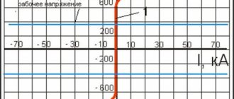
The average shape of the current pulse is shown below. It first increases steeply for about 10 microseconds, and then, having reached its apogee, begins to gradually decrease. Moreover, the decrease to the middle of the maximum current value occurs after 350 μs and continues further until zero.
This lightning impulse creates an overvoltage in the network, which approximately follows the shape of the current, but may differ due to the operation of surge suppressors installed on overhead power lines.
The shape of such a pulse processed by spark gaps is shown a little to the right, and a conventional sine wave with a frequency of 50 hertz is below for comparison.
Power line surge suppressors operate by breaking through a calibrated air gap with an increased discharge pulse. In the normal state, its resistance prevents the flow of currents from a voltage of normal magnitude.
The limiters of high-voltage power lines are quite impressive in size.
On 0.4 kV overhead power lines their dimensions are significantly smaller. They are located on a support next to the insulators.
Overvoltage suppressors for overhead lines are capable of extinguishing very high lightning voltages only up to 6 kilovolts. Such a pulse has a modified voltage rise and fall shape with a characteristic of 8/20 μs. It goes to the input devices of your home.
Transmission line surge protection has greatly reduced and transformed it. But this is clearly not enough to ensure the safety of equipment and residents.
Household wiring 220/380 volts is produced with insulation capable of withstanding impulses of 1.5 ÷ 2.5 kV. Anything bigger breaks it. Therefore, it is necessary to use an additional surge protection device for a private home.
The range of such designs is extensive. They need to be able to select and install correctly.
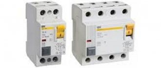
SPDs for a 0.4 kV network are available for 2 possible emergency extinguishing modes:
- discharge current with a form of 10/350 μs, which did not change from the surge arrester of the overhead power line;
- overvoltage pulse with characteristic 8/20 μs.
Based on these factors, it is convenient when choosing an SPD to use the algorithm that I showed in the picture below.
However, one should imagine that there are practically no devices capable of one-time extinguishing a 6 kilovolt pulse to a value of 1.5 kV that is safe for household wiring.
This process occurs in three stages. Each of them uses its own class of SPD, although there are small exceptions to this rule.
Class 1 modules are capable of reducing an overvoltage impulse from 6 to 4 kV, which penetrates:
- after power line limiters;
- or induced by the lightning discharge current flowing down the lightning rod;
- or its impact on nearby buildings, trees, or soil.
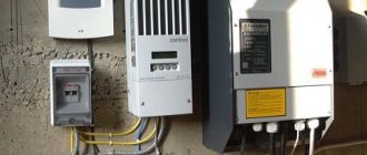
Class 1 surge protectors are installed in the building's input panel inside a separate sealed fireproof cell. Neglecting this rule is dangerous.
During installation, the protected cables must be laid correctly. They should not intersect with the discharge of emergency currents to the ground circuit and incoming, unprotected highways.
The modules are protected from overcurrents by power fuses with fuse links.
Automatic switches are not suitable for these purposes. Their contacts cannot withstand the generated impulse overloads. They are welded, and the damage continues to develop.
The next class of SPD No. 2 reduces the overvoltage impulse from four to 2.5 kV. It is placed in the next distribution board in the hierarchy, for example, an apartment one. It complements the work of the previous module, but can also be used autonomously.
Class No. 3 surge protection devices can be made in modules installed on a DIN rail or in kits built into household appliances, extension cords, and surge protectors.
SPD of class 3 is capable of ensuring safety only after protection of class No. 2 is triggered. It is placed in series behind it because at 4 kilovolts it burns out.
Manufacturers are concerned about the complexity of choosing the correct SPD design and offer a comprehensive solution to this issue with a general module called 1+2+3.
It is placed in a separate box. However, the price of such a development is not affordable for everyone.
Protection of electrical installations from direct lightning strikes
Protection against direct lightning strikes is based on the fact that the direction of the lightning leader is most likely towards the object on which there is a maximum value of the electric field strength. Elevated lightning rods are constructed as objects, which absorb the leader and main lightning discharge.
The correct choice of the location of the lightning rod allows you to virtually eliminate lightning from entering the protected object. To ensure that the voltage on the lightning rod does not exceed the permissible limit and that conditions for damage to the insulation of the protected object do not arise, the lightning rods must be grounded through low resistance.
To protect short objects (buildings, open substations), lightning rods are used.
A rod lightning rod is a tall wooden or steel mast vertically fixed in the ground. At the top of the mast, an lightning rod is strengthened in the form of a steel rod, pipe or corner steel with a cross-sectional area of at least 100 mm2. It must be at least 15 cm and more than 2 m higher than the mast. The lightning rod is connected to a down conductor, which is used as a steel wire with a diameter of at least 6 mm. The current conductor passes down the mast, it is connected to grounding made of rods or angle steel, the spreading resistance of which should not exceed 15...20 Ohms. Grounding is located no closer than 0.5...0.8 m from the foundations of buildings, and for livestock buildings - no closer than 4.5 m from their walls. It is more advisable to protect extended objects (power lines, large substations) from direct lightning strikes with grounded cables stretched over the protected object. It should be noted that it is not recommended to protect lines with voltages up to 35 kV inclusive, and on wooden supports and PO kV from direct lightning strikes for economic reasons.
The protection zone of a single lightning rod up to 60 m high is shown in Figure 11.1. The size of the zone is determined by the ratio
(11.1)
where P=
1 at
h≤3
0m and
P=5.5 h
at height
h
>30m.
For open switchgears of stations and substations, including rural ones, protection zones with a breakthrough probability of no more than 10~2 are adopted, i.e., no more than one lightning strike out of a hundred can hit the protected object.
Rice. 11.1. Protection zone of a single rod lightning rod up to 60 m high:
h
—height of the lightning rod;
hx
is the height of the point on the border of the protected zone;
ha=h- hx —
active height of the lightning rod;
rx
- protection radius at height hx
.
Expected frequency of lightning strikes per year into a single elevated object, including a lightning rod of height h
(m), year-1,
(11.2)
Where n=
0.06 – frequency of lightning strikes into the ground with an area of 1 km2 per 1 hour, (km2•h)-1;
T
— average intensity of thunderstorm activity for a given area, h/year;
R
=3.5
h
– equivalent radius of the circle describing the area from which the lightning rod “collects” lightning, m.
Frequency of lightning strikes to a group of towering structures (including lightning rods)
(11.3)
Where S
– the area limited by circular arcs described by a radius
R
around each lightning rod, and for a structure with a length
l
(m), width
m
(m) and height
h`
(m).
(11.4)
Let's show this with a numerical example. Let there be a transformer substation of size l =
80m,
m =
60m,
h'
= 12m.
Then the frequency of damage to a substation in an area with T
= 60 thunderstorm hours per year will be
or one every 11.8 years, which, of course, is unacceptable. If there is protection by lightning rods with a breakthrough probability of no more than 10-2, a defeat is possible only once every 118 years, i.e. during a period significantly longer than the service life of the substation.
If a single lightning rod does not provide coverage of the entire protected area or a lightning rod is required that is too high, the number of lightning rods should be increased. The protection zone of two lightning rods (double lightning rod) is shown in Figure 11.2.
The external protection zone of lightning rods is the same as for single ones,
using formula (11.1). The smallest width of the protection zone between lightning rods (double lightning rod) is shown in Figure 11.3.
The external protection zone of lightning rods is located in the same way as single ones, using formula (11.1). The smallest width of the protection zone between the lightning rod at level h0
determined by the curves shown in Figure 11.3.
The minimum height of the protection zone for lightning rods up to 30m high is
(11.5)
The protection zone of three or more lightning rods significantly exceeds the sum of the protection zones of single lightning rods. Constructing horizontal sections of the protection zone at level hx
are shown in Figures 11.4 and 11.5 using the example of three- and four-rod lightning rods.
Dimensions bx/2 are determined from curves (see Fig. 11.3) depending on a/ha and the height of the lightning rod. The protection radius rx is determined in the same way as for a single lightning rod.
The necessary condition for protecting the entire area at the ha level for lightning rods up to 30 m high can be written as follows: D < 8 ha (see Fig. 11.4, a and b).
To protect extended objects, mainly wires of overhead power lines with voltages of 110 kV and above, cable lightning rods are used, which are steel cables laid on the same supports above the main wires.
Protection zone of three (a) and four (b) lightning rods of the same height at level hx. The protection zone of a single cable lightning rod up to 30 m high - a horizontally suspended cable - has the shape shown in Figure 11.5, a. The protection zone at level hx is limited by two lines parallel to the cable, located at a distance rx from the vertical plane intersecting the lightning rod. This distance rх, conventionally called the protection radius by analogy with a single rod lightning rod, for h<30 m is determined by the formula
(11.6)
The value of K1 depends on the permissible probability of lightning breaking into the protection zone. For protection with a lightning breakthrough probability of no more than 10-2 K1 = 1.21, and with a lightning breakthrough probability of no more than 10-3 K1 = 0.6.
The construction of a protection zone for two parallel cable lightning rods up to 30 m high is shown in Figure 11.5, b. The external areas of the protection zones are determined as for a single catenary lightning rod. The vertical section of the protection zone between two cable lightning rods is limited by a circular arc passing through the lightning rods and the midpoint between the lightning rods O, located at a height
The value of K3 depends on the specified probability of lightning breaking into the protection zone. For a zone with a breakthrough probability of no more than 10-3 K3 = 3.
To protect an object between two cables, it is necessary to satisfy the condition ha = h - hx> a/K3, which determines the excess of the lightning rod over the protected object.
The frequency of lightning strikes per year into an extended object, including a cable lightning rod of height h and length l (m), in accordance with formula (11.2) is
(11.8)
The protection coefficient of a cable lightning rod is estimated by the tangent of the protection angle a
(11.9)
Two cables are installed on the line with the portal supports. The middle wire finds itself in more favorable shield conditions than the extreme ones. The construction of protection between the cables is shown in Figure 11.6.
Midpoint O of the arc of the protection circle between the cables
The smaller the angle a, the less likely it is for a lightning current to break through the protection zone. However, the angle should not be made less than 15° in order to avoid the cables and wires from tangling when the ice is released. The optimal value is a = 20...24°, and for 35 kV overhead lines, in order to reduce costs associated with increasing the height of supports, a = 35° is considered satisfactory.
Lines with a voltage of 110 kV and higher on reinforced concrete and metal supports are protected with lightning protection cables along the entire length, and lines with a voltage of 35 kV on wooden supports are protected only at the approach to substations with a capacity of more than 2×1.6 MV • And, if the number of thunderstorm hours in th,e 60, and also when there is no redundancy at a voltage of 10 kV.
The length of the protected approach (0.5...2 km) depends on the distance between the valve arresters and the equipment. Approach of 35 kV overhead lines to substations with lower power
they do not protect with a cable, but at the specified length they ground the equipment of reinforced concrete supports and the fastening of insulators on wooden supports. The grounding resistance depends on the resistivity of the soil.
Cable lightning rods protecting the approaches of overhead lines to outdoor switchgear with a voltage of 35 kV and substations of 35/(6... 10) kV are allowed to be connected to the grounded circuits of the outdoor switchgear with a soil resistivity during the thunderstorm season of up to 750 Ohm • m, as well as with a value of 750..1000 Ohm • m, if the area of the substation grounding loop is at least 10 thousand m2. Lines with voltages of 0.38...10 kV do not protect against direct lightning strikes.
Protection of substations from direct lightning strikes depends on voltage, installed power of transformers, number of thunderstorm hours and soil resistivity. Thus, with any number of thunderstorm hours per year, protection from lightning strikes of outdoor switchgear equipment and substations with a voltage of 20...35 kV, power of 1.6 MV • A is not required, and if the number of thunderstorm hours per year is 20 or less, protection of substations of any power is not required.
Lightning rods are installed on the end supports of 35 kV overhead line inputs, protected by a cable, on the racks of structures and the portal of an outdoor switchgear with a voltage of 110 kV, remote from the transformer at a distance of at least 15 m, with a soil resistivity in the thunderstorm season of up to 1000 Ohm • m, and an outdoor switchgear with a voltage of 35 kV - with a specific resistance of up to 500 Ohm • m. If the distance is not less than 15 m, and the specific resistance is not more than 350 Ohm • m, then the resistance of the grounding loop of 35 kV substations should not exceed 4 Ohm • m, and in places where lightning current enters it must be ensured that it spreads in three or four directions. In addition, at a distance of 3...5 m from the current entry point, two or three vertical electrodes 3...5 m long are driven in.
Complete transformer substations with voltage 6...35/0.4 kV, power up to 630 kV • But they do not protect against direct lightning strikes.
Bibliography
Surge protection: private house with single-phase power supply
Installation of electrical wiring in a private house, especially one made of wood and flammable materials, requires careful adherence to electrical safety rules.
It is necessary to take into account that the building can be powered using different grounding schemes:
- typical old TN-C;
- or modern, safer TN-S or its modifications.
Let's look at both cases.
SPD connection diagram: 2 options according to the TN-S grounding system
The picture below shows a detailed circuit with protection of combined class 1+2, which is used for installation after the input circuit breaker.
The surge suppressor varistor is built into the module housing and protects the electrical circuit from direct or remote atmospheric lightning discharges.
The signal flag, traditional for all SPDs, has two colors:
- the green position indicates that the device is working properly and is ready for operation;
- red - about the need for replacement in case of operation or burnout.
Such a module can be used in all grounding systems, not just TN-S. It has 3 connection terminals:
- top left L - phase wire;
- top right PE - protective grounding conductor;
- bottom N - neutral wire.
The SPD protects the electric meter and all circuits after it.
The next diagram shows an option for using protection with an RCD. After it, an additional working zero bus N1 is created, from which all consumers in the apartment are powered.
The scheme seems clear, there should be no questions.
For additional TN-CS and TT grounding systems, I propose two more schemes for study and analysis. They also have an SPD mounted in the input device.
I do not show the meter connection circuits, voltage control relays RKN and RCD, as well as consumers in detail. But the principle is clear: a PE protective bus is used.
But the old grounding system does not have it, which reduces reliability and safety. But it still provides protection, which is why it is considered.
SPD connection diagram using TN-C grounding system
The absence of a PE bus dictates the need to connect an SPD only between the potentials of the phase wire and PEN. There are simply no other options.
The method of installing protection for single-phase wiring is shown on the left, and three-phase wiring is shown on the right.
The overvoltage pulse is removed by the principle of creating an artificial short circuit in the supply circuit.
Surge protection: private house with three-phase power supply
I analyze the principles of connecting SPDs using the example of different grounding systems.
SPD connection diagram for three-phase power supply at home using the TN-S system
Wiring protection is assigned to:
- three-pole input circuit breaker;
- single-pole and three-pole circuit breakers of outgoing lines;
- surge protection device of combined type 1+2+3.
Electricity metering is carried out by a three-phase electric meter. After it, an additional bus N1 is formed in the working zero circuits. All consumers are powered from it.
The N and PE busbars and the SPD module are connected in a standard way.
When using protection classes No. 1, 2, 3 separately, they should be distributed among zones I, II, III.
The penetration of overvoltage pulses from all sides of the phase potentials, working zero and equipment connected to the ground circuit blocks the inclusion of modules between the phase, neutral and PE buses.
SPD connection diagram: 2 options for three-phase power supply at home using the TN-C system
The proposed development does not show a pure option for connecting protections under the TN-C grounding system, but a modification of the transition to TN-CS recommended by modern requirements with re-grounding.
The PEN conductor is supplied through the power cable from the supply transformer substation to its busbar, which is connected by a jumper to the working zero assembly and the re-grounding busbar.
A three-pole SPD, connected after the input circuit breaker, protects the electric meter and all its circuits, including the RCD, from overvoltage pulses. I remind you that it must be mounted in a separate fireproof box.
In the absence of re-grounding, the lower terminal of the SPD module is connected to the PEN conductor bus with a separate core, and the wiring works purely according to the old TN-C system.
Another technique for reducing the rising edge of an overvoltage surge is shown below. Special reactances work here - chokes LL1-3 with an inductance from 6 to 15 microhenry, selected by calculation.
They are used when equipment is located close to each other to create a short delay in the response of the protection required by selectivity conditions.
They are mounted in a separate protective shield together with the SPD. This makes it easier to perform settings, periodic maintenance, and preventive maintenance.
I believe that it is necessary to point out one more option for using surge suppressors and arresters, which is sometimes neglected by owners of complex electronic equipment.
In certain situations, as was the case in my electrical laboratory at a 330 kV substation. The desktop computer was exposed to various types of exposure to electromagnetic fields with frequencies in the low and high ranges. This affected the display of information and even performance.
A solution was found by creating a powerful shielding case and connecting it to a separate functional ground.
However, if lightning strikes nearby soil or lightning protection, such a path can become a source of danger. The situation can be corrected by the method of creating additional galvanic isolation.
It is created by connecting a spark gap. I used a Hakel design, as shown in the picture above.
Lightning, nature and causes of lightning
Lightning is a spark discharge of static electricity accumulated in thunderclouds.
Unlike discharges generated at work and in everyday life, electrical charges accumulated in clouds are disproportionately greater. Therefore, the energy of a spark discharge—lightning—and the resulting currents are very high and pose a great danger to humans, animals, and buildings. Lightning is accompanied by a sound impulse - thunder. The combination of lightning and thunder is called a thunderstorm. A thunderstorm is an exceptionally beautiful natural phenomenon. As a rule, after a thunderstorm the weather improves, the air becomes clear, fresh and clean, saturated with ions formed during lightning discharges.
Despite this, it must be remembered that a thunderstorm in certain conditions can pose a great danger to humans. Every person should know the nature of the thunderstorm phenomenon, the rules of behavior during a thunderstorm and methods of protection against lightning.
A thunderstorm is a complex atmospheric process and its occurrence is caused by the formation of cumulonimbus clouds. Heavy cloudiness is a consequence of significant atmospheric instability. A thunderstorm is characterized by strong winds, often intense rain (snow), sometimes with hail. Before a thunderstorm (an hour or two), atmospheric pressure begins to drop quickly, until the wind suddenly increases, and then begins to rise.
Thunderstorms can be divided into local, frontal, night, and in the mountains.
Most often a person encounters local or thermal thunderstorms. Water vapor in the rising flow of warm air condenses at altitude, releasing a lot of heat, and the rising air flows heat up. Compared to the surrounding air, the rising air is warmer and expands in volume until it becomes a thundercloud. Large thunderclouds contain ice crystals and water droplets. As a result of their fragmentation and friction with each other and with the air, positive and negative charges are formed, under the influence of which a strong electrostatic field arises (the electrostatic field strength can reach 100,000 V/m).
And the potential difference between individual parts of the cloud, clouds or cloud and earth reaches enormous values.
When the critical electrical intensity in the air is reached, an avalanche-like ionization of the air occurs - a lightning spark discharge.
A frontal thunderstorm occurs when a mass of cold air moves into an area where warm weather prevails. Cold air displaces warm air, with the latter rising to a height of 5-7 km. Warm layers of air invade into vortices of various directions, a squall is formed, strong friction between the layers of air, which contributes to the accumulation of electrical charges. The length of a frontal thunderstorm can reach 100 km. Unlike local thunderstorms, it usually gets colder after frontal thunderstorms.
Night thunderstorms are associated with the cooling of the ground at night and the formation of eddy currents of rising air.
Thunderstorms in the mountains are explained by the difference in solar radiation to which the southern and northern slopes of the mountains are exposed. Night and mountain thunderstorms are not strong and short-lived.
Thunderstorm activity varies in different areas of our planet. World centers of thunderstorms: Java Island - 220 thunderstorm days per year, Equatorial Africa - 150, Southern Mexico - 142, Panama - 132, Central Brazil - 106. Russia: Murmansk - 5, Arkhangelsk - 10, St. Petersburg - 15, Moscow - 20. As a rule, the further south (for the northern hemisphere of the Earth) and the further north (for the southern hemisphere of the Earth), the higher the thunderstorm activity. Thunderstorms are very rare in the Arctic and Antarctic. There are 16 million thunderstorms on Earth per year. For every m of the Earth's surface there are 2-3 lightning strikes per year. The ground is most often struck by lightning from negatively charged clouds.
By type, lightning is classified into linear, pearl and ball.
Pearl and ball lightning are quite rare occurrences.
The common linear lightning, which every person encounters many times, has the appearance of a branching line. The current strength in the linear lightning channel is on average 60 - 170 kA; lightning with a current of 290 kA has been recorded. The average lightning has an energy of 250 kW per hour (900 MJ).
The discharge develops in a few thousandths of a second; at such high currents, the air in the lightning channel zone almost instantly heats up to a temperature of 30,000 - 33,000°C. As a result, the pressure rises sharply, the air expands and a shock wave appears, accompanied by a sound impulse - thunder.
Pearl lightning is a very rare and beautiful phenomenon. Appears immediately after linear lightning and disappears gradually. Most often, a pearl lightning discharge follows a linear path. The lightning appears to be 12 m apart and resembles pearls strung on a string. Pearl Lightning may be accompanied by significant sound effects.
Ball lightning is also quite rare. For thousands of ordinary linear lightning, there are 2-3 ball lightning. Ball lightning, as a rule, appears more often towards the end of a thunderstorm, less often after a thunderstorm. It can have the shape of a ball, ellipsoid, pear, disk, or even a chain of balls. The color of lightning is red, yellow, orange-red.
Sometimes lightning is dazzling white with very sharp outlines. Color is determined by the content of various substances in the air. The shape and color of lightning may change during a discharge. It was not possible to measure the parameters of ball lightning and simulate it in laboratory conditions. Apparently, many observed unidentified flying objects (UFOs) are similar or similar in nature to ball lightning.