In industrial and household electrical networks, equipment is installed that operates within specified limits of current and voltage. However, at supply transformer substations and powerful power electric motors it is necessary to periodically change operating modes. The transition process is characterized by a sharp pulse increase in the electrical parameters of the network. The most dangerous are atmospheric discharges in the form of lightning, where the surge surge reaches a critical value that can damage electrical equipment. To prevent such emergency situations, a surge voltage limiter is used.
Principle of operation
In pulsed transients, the voltage changes much faster than the current. Therefore, the classic current circuit breakers known to everyone will be ineffective here. The presence of a limiter with a semiconductor element having a nonlinear current-voltage characteristic provides electrical network devices with protection from high voltage pulses.
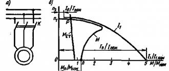
As can be seen from the graph, at the nominal voltage value the resistance of the semiconductor (it is called a varistor) is quite large and the current passing through it is practically zero (zone 1). When a varistor is exposed to high-voltage pulses (zone 2), its resistance decreases sharply, approaching almost zero (zone 3). In this embodiment, the limiter varistor will act as a shunt connection that takes on the entire current load, which is directed to the ground loop.
What is an SPD
SPD: features of selection and application
Even short-term impulse voltage surges, several times higher than the nominal voltage, can cause irreparable damage to expensive electrical equipment and electronics, and even cause a fire. Overvoltage in networks can occur due to thunderstorms, accidents or transients. For example, pulse overvoltages can result from lightning hitting a lightning protection system or power line, switching powerful inductive consumers such as electric motors and transformers, or short circuits.
What is an SPD and what is it for?
A surge limiter in electrical installations with voltages up to 1 kV is called a surge protection device - SPD. Surge protection devices are precisely designed to protect electrical equipment from such situations. They serve to limit transient overvoltages and drain current pulses to ground, reducing the amplitude of the overvoltage to a level that is safe for electrical installations and equipment. SPDs are used both in civil engineering and industrial facilities.
The main Russian document defining what an SPD is is GOST R 51992-2002, “Devices for protection against surges in low-voltage power distribution systems.”
SPDs are designed to provide protection from lightning strikes to the lightning protection system of a building (facility) or overhead power line (power line), to protect highly sensitive equipment and machinery from surges and switching power surges. SPDs with quick-release mounts for installation on a DIN rail are widely used.
Surge voltage protection devices include devices of several categories:
| Device type | What is it for? | Where is it used? |
| I class | For protection against direct exposure to lightning. Protects against 10/350 μs pulses: lightning entering an external lightning protection system and lightning striking a power line near an object. The amplitude of pulse currents with a wave front steepness of 10/350 μs is in the range of 25-100 kA, the duration of the wave front reaches 350 μs. |
|
| II class | They provide protection against overvoltages caused by switching processes, as well as performing the functions of additional lightning protection. Designed for protection against 8/20 µs pulses. They protect against lightning strikes in power lines and switching in the power supply system. Current amplitude is 15-20 kA. |
|
| III class | For protection against surges caused by residual voltage surges and asymmetrical voltage distribution between phase and neutral. They also work as high-frequency noise filters. Designed for protection against residual pulses of 1.2/50 μs and 8/20 μs pulses after SPDs of classes I and II. | Used to protect sensitive electronic equipment close to which they are installed. Typical applications include IT and medical equipment. Also relevant for a private house or apartment - they are connected and installed directly at consumers. |
The design of SPDs is constantly being improved, their reliability is increasing, and the requirements for maintenance and monitoring are being reduced.
How does an SPD work?
SPD eliminates overvoltages:
— Asymmetrical (common-mode) mode: phase - ground and neutral - ground.
— Symmetrical (differential) mode: phase - phase or phase - neutral.
In single-ended mode, when the voltage exceeds a threshold value, the protection device discharges energy to ground.
In symmetrical mode, the energy removed is directed to another active conductor.
SPD connection diagram in single-phase and three-phase networks of the TN-S system. The TN-C grounding system uses a three-pole SPD. It does not have a contact for connecting the neutral conductor.
According to the principle of operation of SPDs, valve and spark gaps, often used in high voltage networks, and surge suppressors with varistors are divided.
In arresters, when exposed to a lightning discharge as a result of overvoltage, an air gap breaks through the jumper connecting the phases to the ground loop, and a high voltage pulse goes into the ground. In valve-type arresters, the high-voltage pulse in a circuit with a spark gap is suppressed by a resistor.
SPDs based on gas-filled arresters are recommended for use in buildings with an external lightning protection system or supplied with electricity via overhead lines.
In varistor devices, the varistor is connected in parallel with the protected equipment. In the absence of pulse voltages, the current passing through the varistor is very small (close to zero), but as soon as an overvoltage occurs, the resistance of the varistor drops sharply, and it passes it through, dissipating the absorbed energy. This causes the voltage to drop to nominal and the varistor returns to non-conducting mode.
The SPD has built-in thermal protection, which provides protection against burnout at the end of its service life. But over time, after several trips, the varistor surge protection device becomes conductive. The indicator informs about the end of its service life. Some SPDs provide remote indication.
How to choose an SPD?
When designing surge protection in networks up to 1 kV, as a rule, three levels of protection are provided, each of which is designed for a certain level of pulse currents and wave front shape. Arresters (class I surge arresters) are installed at the input, providing lightning protection. The next class II protective device is connected in the distribution board of the house. It should reduce overvoltages to a level that is safe for household appliances and the electrical network. In the immediate vicinity of equipment sensitive to surges in the network, you can connect a class III surge protector. It is preferable to use SPDs from one vendor.
To coordinate the operation of the protection stages, the devices must be located at a certain distance from each other - more than 10 meters along the power cable. At shorter distances, a choke must be turned on to compensate for the missing active-inductive resistance of the wires. It is also recommended to protect the SPD using fuse links.
With cascade protection, a minimum spacing of 10 m is required between protection devices.
SPD classes are not unified and depend on the specific country. Each construction organization can refer to one of three test classes. The European standard EN 61643-11 includes certain requirements from the IEC 61643-1 standard. Based on IEC 61643, the Russian GOST R 51992 was created.
Assessing the significance of protected equipment.
The need for protection, the economic benefits of protective devices and the corresponding protective devices must be determined taking into account the risk factors: the relevant standards are prescribed in IEC 62305-2. Design, installation and maintenance criteria are considered for three separate groups:
| Group | What does it include | Where is it determined |
| First | Protective measures to minimize the risk of damage to property and harm to human health | IEC 62305-3 |
| Second | Protection measures to minimize electrical and electronic system failures | IEC 62305-4 |
| Third | Protection measures to minimize the risk of property damage and utility network failures (mainly electrical and telecommunication lines) | IEC 62305-5 |
Assessment of the risk of impact on the object.
The standards for installing lightning arresters are prescribed in the international standard IEC 61643-12 (Principles of selection and application). The international standard IEC 60364 (Electrical installations of buildings) contains several useful sections:
— IEC 60364-4-443 (Protection for safety).
If the installation is supplied from or includes an overhead line, a surge protection device must be provided if the lightning level for the facility in question corresponds to exposure class AQ 1 (more than 25 thunderstorm days per year).
— IEC 60364-4-443-4 (Selection of installation equipment).
This section helps in selecting the protection level for the arrester depending on the loads to be protected. The rated residual voltage of protective devices must not exceed the impulse withstand voltage category II.
Selection of equipment according to IEC 60364.
As the first stage, it is better to use an SPD based on arresters without a removable module. It is unlikely that you will be able to find a varistor device with a rated current Iimp of more than 20 kA. The cabinet in which an SPD of this type is installed must be made of fireproof material.
The most important parameter characterizing the SPD is the protection voltage level Up. It should not exceed the resistance of electrical equipment to impulse voltage. For class I SPDs Up does not exceed 4 kV. The protection voltage level Up for devices of class II should not exceed 2.5 kV, for class III - 1.5 kV. This is the level that technology must withstand.
There are a few more important parameters that you need to know to select an SPD. The maximum long-term operating voltage Uc is the effective value of alternating or direct current that is continuously supplied to the SPD. It is equal to the rated voltage, taking into account possible overvoltage in the electrical network.
Minimum required Uc value for SPD depending on the network grounding system.
Rated load current IL is the maximum continuous alternating (rms value) or direct current that can be supplied to the load. This parameter is important for SPDs connected to the network in series with the protected equipment. SPDs are usually connected in parallel to the circuit, so this parameter is not indicated.
Selection of protective equipment: sensitive equipment and building equipment.
Selection of protective equipment: household appliances and electronics.
Selection of protective equipment: production equipment.
Selection of protective equipment: critical equipment.
Today, many large consumers of electrical energy successfully use high-quality SPD elements in Russia. Positive test results and the effectiveness of using SPDs in Russia suggest that their use in Russian conditions is profitable and convenient. All that remains is to select the desired device model and install it on site.
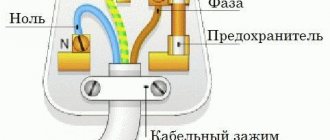
Design
In addition to the main element - a varistor with nonlinear characteristics, the surge suppressor is distinguished by a special housing made of porcelain or polymer. The varistor itself is made in most cases from vilit disks (from a special ceramic composition with a base in the form of zinc oxides with special additives). The disks are covered with insulating coating and installed in the housing.
Depending on the operating conditions, surge suppressors can have different designs.
- For installation on power lines and protection of equipment at industrial facilities.
- Protection against peak impulses of household equipment in a house or apartment is provided by compact devices with an attractive design.
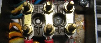
The following structural elements are indicated by numbers in the image:
- 1 - body;
- 2 - fuse, tripped after the passage of a voltage pulse, with short-circuit current parameters;
- 3 - varistor module, easily replaceable without disconnecting the base element;
- 4 - indicator showing the current operating life of the device;
- 5 - notches on the contact clamps, increasing the density and area of contact in order to prevent the wires from melting as a result of heating.
Main types
The type of network interference includes both overvoltage associated with a phase imbalance of a longer duration, and overvoltage caused by a lightning discharge.
Important! When a pulse overvoltage occurs, this indicates the occurrence of a short-term high voltage between phases or phase and ground with a duration, usually up to 1 ms.
A lightning discharge is a powerful impulse overvoltage. It occurs when lightning strikes an electrical system. If the distance from a lightning strike reaches up to 1 km, then such a pulse overvoltage can cause failure of electrical equipment. A direct impact produces an instantaneous pulse current of up to 100 kA/s. Typically, the discharge duration is up to 1 mS.
What types of voltage limiter are divided into?
If there is a lightning rod system, the discharge pulse can be evenly distributed between the lightning rod, power supply, communication line, and household communications. This process depends on the design of the structure itself, the communication system, and the laying of the line.
Switching in the power grid causes pulsed power overvoltage. For example, if you disconnect an isolation transformer that has a power of 1 kVA 220/220 V from the network, then all the energy is released into the load in the form of a high-voltage pulse with a voltage of up to 2 kV.
The power of any transformer in the power grid is much greater, and accordingly, the emissions will be more powerful. In addition, switching occurs against the background of an arc, which becomes a source of radio frequency interference.
Note! The electrostatic charge that accumulates during the operation of technological equipment, although it has little energy, is discharged at an unpredictable moment.
The amplitude and type of overvoltage pulse vary not so much from the source of interference, but from the parameters of the network itself. No two cases of surge overvoltage are the same, but for the production and testing of protection devices there is a standard for the parameters of current, shape and voltage, overvoltage in different cases.
For example, for the expected current from a lightning discharge, a current pulse of 10/350 μs is taken, and for the indirect effects of lightning and various switching overvoltages, a current pulse with characteristics of 8/20 μs is taken. When comparing two devices with a high pulse discharge current of 20 kA at 10/350 μs and 20 kA at a pulse of 8/20 μs, the real power of the first will be 20 times greater.
Switching protective devices
Such limiters have other names, for example, spark gap. The operating principle of this device is based on the use of the spark gap phenomenon. The design has an air gap in the jumper, which serves to connect power lines to the ground loop. The circuit in the jumper is open at rated voltage.
Switching protective devices are also called spark gaps
If a lightning discharge occurs due to overvoltage in the power line, an air gap breakdown will occur, the circuit between the phase and the ground will be closed, and the high voltage pulse will be directly grounded. The design of the valve arrester in a circuit with a spark gap is like a resistor on which high voltage pulses are suppressed. As a rule, arresters are used in high-voltage networks.
Limiters (SPD)
Thanks to new devices, it was possible to replace the more outdated huge models. To determine the performance of the limiter, you should carefully familiarize yourself with the characteristics of the nonlinear resistor, since the arrester operates on the basis of the current-voltage function.
In the production of varistors, zinc oxide material is usually used. The formation of the component occurs due to the combination of the solution with other substances. The result is a pn junction with current-voltage characteristics. If the voltage in the network corresponds to the nominal parameters, then the current in the varistor circuit is zero. When an overvoltage occurs in a pn junction, the current conductivity increases. Because of this, the voltage value drops to the nominal value.
You may be interested in Installing a motion sensor
Characteristics of the network surge suppressor
Note! After standardizing the network parameters, the varistor returns to non-conducting mode without affecting the operation of the device.
Combined
Combined devices operate under normal operating conditions with unfavorable voltages from 0.94 to 1.96 values. These models are equipped with a resistor. In action, the combined device not only grounds the voltage, but also simultaneously stabilizes the value in the structure itself.
Combined surge arrester
Classes
Such devices are divided into several categories:
- I prevents direct exposure to lightning strikes. As a rule, such devices have input distribution equipment (ADS). It is usually used for administrative and industrial buildings and residential apartment buildings;
- II helps to protect the distribution network from overvoltages that may be caused by switching or secondary protection functions. This is done to prevent exposure to a strong lightning strike. As a rule, they are installed and connected directly to the network in the panel;
- III carefully protects equipment from voltage surges that may result from residual surges and asymmetrical voltage distribution between phase and neutral lines. The operating principle of such a device is to operate in high-frequency interference filter mode. They are connected and installed in private houses or apartments. Particularly popular is the product made in the form of a module. This device can be easily installed on a DIN rail.
What classes are SPDs divided into?
Specifications
In addition to the design, an equally important factor when choosing the required (pulse) surge suppressor (SPD) is its following main technical parameters.
- The maximum operating voltage that acts on the surge arrester indefinitely without affecting its performance.
- The maximum voltage acting on the surge arrester for the time specified by the manufacturer without causing any damage to it.
- By applying operating voltage to the ends of the arrester, the current passing through the insulation is measured. This parameter is called leakage current. Its value in a good condition of the limiter tends to zero.
- Discharge current - its value determines the identity of the surge limiter in protection against various factors causing voltage surges: lightning, electromagnetic, switching.
- Ability to withstand emergency operation while maintaining the integrity of all structural elements.
Device selection criteria
How to choose the right SPD with any working element (varistor, spark gap, breakdown diode)? In general, the following factors should be considered:
- The main parameters of the network include rated current and voltage. The protection effect (throughput and protection voltage level) is also taken into account;
- factors that may affect the installation (design, device connection process);
- To protect the power circuit from negative factors, you need to install an SPD, taking into account the concept of the area. When choosing a device type, you should pay attention to the current load. The control and measurement circuit protection system is based on the type of signal to be protected and the choice of SPD;
- Initially, the basic parameters of the protected circuit are determined. Taking into account the rated withstand voltage, the low voltage 380/220 V network is divided into 4 categories (I-IV). Their normalized values are 1.5; 2.5; 4.0 and 6.0 kV. The class of the SPD must correspond to the level of protection.
What criteria are used to select a voltage limiter?
Please note! The protection level of the selected SPD should not be greater than the withstand voltage of the network.
Also, device parameters are determined by:
- rated voltage;
- maximum continuous operating voltage for a long time;
- the amplitude of the pulse current, which can pass once without damaging the circuit and the protection device (this belongs to class 1);
- pulse amplitude with an indicator of 8/20 μs, SPD (for class II);
- amplitude of the current pulse passing through the SPD. Therefore, the surge protection device can withstand many times;
- the upper level of protection voltage, which characterizes the SPD, limiting the voltage at the terminal when current flows;
- permissible accompanying current (for arresters);
- response time.
Kinds
The classification of (pulse) surge suppressors is determined by state standards. Regulatory documents indicate the basic requirements for protection devices depending on the nature of the source. The following overvoltage protection groups are distinguished:
- from short circuits on the high side of low-voltage networks;
- from the effects of lightning discharges and voltage surges caused by switching industrial electrical installations;
- from possible overvoltages caused by electromagnetic factors.
Depending on the specific type of issue being addressed, surge suppressors may differ from each other in such parameters.
- Voltage class. Limiters protect circuits whose operating voltages range from less than 1 kV to significantly higher values. There are, for example, surge arresters for voltage classes of 0.38 kV and 0.66 kV, surge arresters for voltage classes of 3, 6, 10 kV and others.
- Insulating jacket material. The most widespread are porcelain and polymers.
Ceramic surge arresters have good resistance to sunlight and have sufficient mechanical strength, which expands the possibilities of operation in different conditions. The use is limited only by the large weight characteristics and the nature of the spread of fragments upon rupture from a safety point of view.
Polymer surge arresters successfully compete with porcelain ones. With many times lower weight characteristics and practically safe in case of destruction by excess pressure, they are in no way inferior in dielectric properties. The disadvantages include the ability to cover the surface with dust, which increases the leakage current and causes insulation breakdown. In operation, they are more susceptible to the influence of solar radiation and fluctuations in ambient temperatures than porcelain (pulse) surge arresters.
- Security class. The possibility of installing it outdoors or indoors depends on the hermetic manufacturing of the surge arrester housing, which actually determines this indicator.
- Single-column surge arresters. They consist of one modular block of varistors with a different set of disks made of a protective semiconductor element, designed for all voltage classes.
- Multi-column surge arresters. Consist of several modular blocks. They are more reliable than single-column designs.
SPD for a private house: connection and diagram
A protective device for a private home can be connected via single-phase and three-phase networks, while for SPDs the connection diagram may be different.
Connecting equipment in a private home
Single-phase network (TN-S)
As an example, the Easy9 series electrical system from Schneider Electric. The conductors are connected according to the following principle: phase, neutral conductor for protection. It is usually installed after turning on the machine. All contacts for connection on any device are indicated.
How to connect to TN-S
Note! Connecting the SPD through the switched on circuit breaker will make it easy to determine where the phase is and where the zero is. A green mark on the body indicates working condition, and a red mark indicates a malfunction.
Three-phase network (TN-S)
The Easy9 series device is manufactured by Schneider Electric. It is used for a three-phase network. This electrical equipment alone cannot prevent direct lightning strikes. It is recommended to protect the equipment using a special fuse.
Three-phase network (TN-C)
Connection to the TN-CS grounding system is carried out according to modern standards. The first option is a 4-pole input circuit breaker, and the second is a 3-pole input.
Note! When installing multi-stage overvoltage protection, that is, installing class 1 SPDs in the ASU of a building together with class 2 SPDs in the distribution boards of the building and with class 3 SPDs, for example, in sockets, it is necessary to maintain a cable gap of about 10 m .
SPD is an extremely important device. Each grounding system needs to select the appropriate type. To make the right choice, it is advisable to listen to the advice of experienced specialists.
What does the abbreviation UZIP mean?
SPD stands for surge protection device. In addition to surge suppressors, the list of devices included in the SPD includes already outdated valve and spark gaps. The latter are used in high voltage networks (power lines).
The use of semiconductor varistors as a material made it possible to make the dimensions of the SPD so compact that it became possible to use it as protection against voltage surges in private houses and apartments.
SPD: features of selection and application
Even short-term impulse voltage surges, several times higher than the nominal voltage, can cause irreparable damage to expensive electrical equipment and electronics, or even cause a fire. Overvoltage in networks can occur due to thunderstorms, accidents or transients. For example, pulse overvoltages can result from lightning hitting a lightning protection system or power line, switching powerful inductive consumers such as electric motors and transformers, or short circuits.
How to connect surge protectors at home
The rules for the design of power installations regulate the mandatory installation of surge protectors in houses where power supply is provided by overhead lines and with a relatively long period of thunderstorms. There are a large number of SPD models on the market, such as, for example, surge voltage limiters OIN 1, OPS 1, OPN-RV and many others, the dimensions of which allow them to be placed in the incoming power supply panel of a private house.
The power supply to the house can be organized using single-phase or three-phase circuits. The organization of the grounding system of the home electrical network may also be different.
The image below shows a diagram of connecting an SPD to a single-phase electrical circuit. A grounding system with two neutral wires: one acts as a neutral conductor connected to the ground, and the second is used as a protective wire.
In the diagram:
- phase - indicated by a black wire;
- zero - indicated by a blue wire;
- green - protective ground wire.
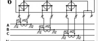
The following image shows a diagram of connecting an SPD to a three-phase electrical circuit. The design of the protection device and the meter is made for a three-phase network. The grounding is equipped according to the same principle as in the example with connection to a single-phase circuit.
In the diagram:
- black wire - the first of three phases;
- red wire - the second of three phases;
- brown - third phase;
- blue - neutral ground wire;
- green - protective ground wire.
How to determine the type of grounding system
To determine the type of grounding system, you need to consider the PEN conductors, that is, how they are separated. If everything is ready, the wiring is similar to the TN-CS system. In this case, for a three-phase circuit, five main wires come from the main distribution panel of the house, but for a single-phase circuit, only three wires are used. PEN conductors are divided into two components: PE and N.
Note! If it is not split, the wiring will work according to the TN-C system, with 4 wires from the three-phase system and 2 wires from the single-phase system coming from the distribution panel.
Based on the principles described, the type of grounding system can be easily determined. In all cases when the TN-C system is used in private homes, it is recommended to transfer it to the TN-CS scheme, which is more promising and safer.
You might be interested in Electricity metering: diagram
How to calculate a grounding system
Installation recommendations
If you follow the recommendations for installing and connecting a surge suppressor, the device will guarantee the safe operation of household equipment.
- It is important to have a very reliable grounding. Protection with an unreliable grounding loop, even with a not very large surge in the voltage pulse, will lead to an emergency in the form of burnt electrical appliances and the panel itself.
- It is necessary to ensure that the protection class of the SPD matches the installation location of the shield. If the shield is located outdoors, and the device is intended to work indoors, then at best it will fail, at worst it will harm the home electrical network.
- To ensure reliable protection, in some cases it is necessary to install SPDs of different protection classes.
- Not every protective device is suitable for a specific type of grounding of the home electrical network. You should carefully study the technical documentation of the device you are purchasing so as not to waste money on a fairly expensive device.
- It is important to connect the circuit correctly, without any violations. If you do not have the skills of an electrician, you should not take on the job. A qualified specialist will do it correctly, without much difficulty.
Lightning strikes, downed power lines or accidents at transformer substations cannot be predicted. Installing an arrester will protect you from unexpected troubles.
Operating principle of the device
The operating principle of the protective device is quite simple. Typically, a surge protector can eliminate an overvoltage instantly. This is a simple voltage tapping circuit. For example, if the voltage is normal, then the resistance of the varistor will be determined by megaohms. If an overvoltage appears on the line, then the varistor moves to the cable category. An electric current passes through the conductor and flows to ground.
How does a voltage limiter work?
For your information! The operating principle of SPDs is classified into two categories: valve/spark arresters. They are usually used for high voltage networks, like protective devices with varistors.
When the action of a lightning discharge during overvoltage is detected in the arresters, then this can break through the air passage in the jumper that connects the phases to the ground loop. A high voltage pulse hits the ground. In the case of valve-type arresters, the reduction of the high-voltage pulse in the circuit with the spark gap occurs through a resistor.
SPDs in gas-filled arresters are suitable for buildings where an external lightning protection system or electricity supply occurs through the air due to special lines.
Equipment with a varistor is connected in parallel with the protected device. In the absence of pulse voltage, the current flowing through the varistor is almost zero. However, when an overvoltage occurs, the resistance of the equipment drops sharply, it allows current to pass, dissipating the absorbed energy, causing the voltage to drop to its nominal value. Thus the varistor returns to non-conducting mode.
The SPD has built-in thermal protection, which prevents burnout at the end of its service life. However, over time, the device breaks down and the voltage limiter needs to be replaced. The indicator itself informs about problems.
You might be interested in what a capacitor looks like in the diagram
Characteristics and markings
Each protective device of one class or another has individual parameters that are taken into account when connecting an SPD. The main technical characteristics are applied to the product body, and full information is reflected in the passport. When choosing a device, you must first pay attention to the designation and the following indicators:
- The nominal and maximum voltages at which the device can operate normally for a specified time.
- An indicator of the operating frequency of the current for which the SPD is calculated.
- The value of the rated discharge current. Next to the numbers the shape of its wave is indicated. It is a current pulse with a wave of 8/20 ms, expressed in kA, passed through the device repeatedly, without any consequences.
- The value of the maximum discharge current that the protection passes once without losing its overall performance.
- The protection voltage level indicates the device's overvoltage limiting capabilities.
How to choose
When choosing an SPD with any working element (varistor, spark gap, breakdown diode), the following factors should be taken into account:
- Network parameters (rated current, voltage, transmission parameters), protection effects (throughput and protection voltage level).
- Factors influencing the installation (design, connection conditions).
The principle of power circuit protection is to install the SPD according to the concept of the area, and when choosing a type, it is important to reliably evaluate its current load. The control and measurement circuit protection system is based on the type of signal to be protected and the choice of SPD. First you need to determine the parameters of the protected circuit. In accordance with the rated withstand voltage, the low voltage network 380/220 V is divided into 4 categories (I - IV) with standardized values of 1.5; 2.5; 4.0 and 6.0 kV. The SPD class corresponds to the protection level: level I-≤4 kV; level II-1.3 ... 2.5 kV; level III-0.8 ... 1.5 kV. The protection level of the selected SPD must not exceed the withstand voltage of the mains.
You might be interested in Installing a single-phase meter
In addition, the device has the following parameters:
- Rated voltage.
- Maximum continuous operating voltage (mains operating voltage over a long period of time).
- The amplitude of the pulse current that can pass at least once without damaging the circuit and the protective device (for class I).
- Pulse amplitude is 8/20 µs, SPD at least once non-destructive (for class II).
- The amplitude of the current pulse flowing through the SPD that the surge protection device can withstand many times.
- Upper level of protection voltage - characterizes the SPD, limiting the voltage at the terminal when current flows.
- Permissible accompanying current (for arresters).
- Response time.
Definition of the grounding system
The type of grounding system used in a home can be determined by how the PEN conductors are separated. If everything is ready, the wiring is similar to the TN-CS system. In this case, for a three-phase circuit, five main wires come out of the main distribution panel of the house, and for a single-phase circuit, only three wires. PEN conductors are divided into PE and N components.
On a note! If it is not split, the wiring will work according to the TN-C system, with 4 wires from the three-phase system and 2 wires from the single-phase system coming from the distribution panel.
Based on the principles described, the type of grounding system can be easily determined. In all cases when the TN-C system is used in private homes, it is recommended to transfer it to the TN-CS scheme, which is more promising and safer.
Importance of protected equipment
Protected objects are divided into several classes:
- Special (critical) objects harmful to the environment, human and animal life. Examples: chemical and petrochemical products, biochemical and bacteriological centers, production of explosives, nuclear power plants, etc. The reliability of protection against lightning strike reaches 0.98 (for individual items in category A zones it can be set at a higher level of 0.995) . Negative consequences of lightning strikes: fires, explosions, releases of toxic substances, increased radiation over large areas, environmental disasters resulting in irreparable material and human casualties
- Types of special objects that pose a danger to the environment. Examples: oil refining, gas stations, flour mills, wood processing plants, production of plastic products, etc. The reliability of protection is guaranteed to be 0.95. Negative effects of lightning strikes: fires, explosions in and around the area. Walls and ceilings can collapse, causing serious injury and even death to employees and visitors. In this case, significant financial losses will be recorded.
- The object is a special critical infrastructure. Types of objects: communications and ICT enterprises, pipeline transport, power lines, central heating equipment, transport infrastructure, etc. Impact protection reliability is guaranteed - 0.9. Negative consequences of lightning strikes: communication disruption, partial or complete loss of control, interruption of water and heating, temporary reduction in quality of life and loss of material.
- General, industrial and civil facilities and associated infrastructure. Examples: residential buildings, industrial buildings (up to 60 m high), houses and huts in villages, social and cultural facilities, educational institutions, hospitals and museums, temples, churches. Guarantee against lightning strikes −0.8. Negative consequences of lightning strikes: severe fires, damage to buildings, disruption of transport, disruption of communication systems, possible loss of historical and cultural heritage. Significant material and financial losses. May cause personal injury or death.
You might be interested in Installing a three-phase meter
On a note! From the above classification system it is clear that any type of protected object differs from another in terms of the characteristics and purpose of lightning protection of the installation and the type of grounding device; its design is determined by the purpose and location of the structure.
Object exposure risk
Connecting SPDs of various classes together with a grounding system reduces the risk of equipment breakdown due to a power surge or lightning strike by 80-99%.
Preparing for work
Choosing and purchasing a voltage stabilizer for your home is only the initial stage that you will have to face if you decide to protect your household appliances from emergency situations in the electrical network. The next step should be to find an answer to the question - how to connect and install a voltage stabilizer?
connect the stabilizer to your home network
So, before starting installation work, you need to remove the device from the packaging and inspect it for possible mechanical damage. If the stabilizer has been at a negative temperature for a long time (during transportation), it should be kept for at least 2 hours before connecting it to the network. This will avoid the appearance of condensation when the equipment heats up during operation.
Next we move on to the question of how to install a voltage stabilizer for the home? The equipment may be installed indoors, where it will not be exposed to construction dust or other aggressive environments. There should be no flammable materials near the stabilizer.
Watch the video, connection steps:
https://youtube.com/watch?v=gsmqpvq0YFM
The device body must be grounded, and the connection to the network is made through the corresponding pair of terminals located on the rear panel. The stabilizer is turned on using a circuit breaker; the voltmeter should show 220 V. A load is connected to the output terminals and only after that can the switch be turned on.
How to calculate stabilizer power
To choose the right model, you need to decide which electrical appliances will be connected to the device. You can determine their power consumption using one of the methods provided on the Internet or use the simplest of them. It is as follows. There is a circuit breaker on the electrical panel, the rating of which is selected in such a way as to protect the wiring from damage due to overload.
Watch the video to correctly calculate the power of the device:
But how to calculate the power of a voltage stabilizer for your home? From the physics course we know that this parameter is equal to the product of current and voltage. The values of these quantities are easy to determine. The voltage in a single-phase network is 220V, and the rated current is usually indicated on the circuit breaker. Let's say it is 16A, then the power will be 16*220=3520 W. But you need to choose a stabilizer with a margin of at least 30%. This is due to the fact that as the voltage increases, the output power drops.
Device malfunctions and their solutions
Possible options for equipment failure are usually given in the documentation supplied with it. Among them, the following malfunctions most often occur:
- Spontaneous shutdown of the device usually occurs due to exceeding the permissible load;
- The network indicator light does not light up if the device is not connected, the fuse is faulty or the connections are mixed up;
- It is not possible to achieve an output voltage of 220 V with an unacceptable load;
- There is no stabilization - this may be due to problems with the input-output button or turning off the Bypass mode.
Expert advice
Many consumers are interested in the answer to this question. Those who believe that this can increase the power of the stabilizer are mistaken. On the contrary, the output parameters will correspond to the value produced by the weakest device in the network. For example, if three devices of 5;10;15 kW were connected in parallel, then the output power will be only 5 kW, since this figure is the lowest.
Types of surge arresters
- Voltage class - the operating value for which the limiter is designed, is divided into devices up to 1 kV and higher, as a rule, the voltage rating corresponds to the standard value of the electrical parameters of the network (6, 10, 35 kV).
- Jacket material - determines the type of insulation of the outer layer; porcelain or polymer models are most often used.
- Security class - determines the possibility of installation either in an open part or only indoors.
- Number of elements or phases - the number of surge suppressors depends on the number of protected phases and the magnitude of the voltage supplying them.
Depending on the causes of overvoltage in the network, the protection device must be built in accordance with the requirements of the standards:
- GOST R 50571.18-2000 – against possible overvoltages in low-voltage networks during short circuits on the high side.
- GOST R 50571.19-2000 – against surges caused by lightning and resulting from switching electrical installations.
- GOST R 50571.20-2000 – against overvoltages generated by electromagnetic influences.
The combination of several types allows you to build multifunctional or step limiters.
Surge suppressors - how to connect the device
There are connection diagrams for both one phase and three phases. In addition to the OIN-1 device described here, there are many identical protective voltage limiters from different brands, so the principle of their connection is no different from each other. The typical circuit presented below can practically be used with any type of device.
In the first option, the device is connected to the circuit according to a parallel connection scheme, the second option shows a connection in series with a disconnector. It follows from this that when the surge suppressor operates with a sharp increase in the mains voltage, the disconnector will open the supply circuit.
Attention! In addition to the correct installation of the phase and grounding cables, the cross-section and length of the installation wire are of significant importance.
From the connection point on the terminal block of the device to the grounding bus, the length of the installation wire should not be more than 500 mm.
Stages of installation of surge protectors in a distribution board
Let's consider a household case when a distribution switchboard with an arrester is assembled for an apartment or a private house, a panel of the appropriate volume is selected to accommodate a meter, an input circuit breaker and individual circuit breakers in groups, an SPD of the surge arrester type for installation on a DIN rail. When all elements with the appropriate technical characteristics and wires for connection have been purchased, you can begin installation:
- On the back wall inside the control panel, a sheet plate is fastened with screws, on which DIN rails and all other elements are installed. For ease of assembly, remove this plate and mount it on a table;
- First of all, the metering unit (meter) is attached to the plate, usually in the upper left part;
- On the right side of the meter, we attach a DIN rail of the appropriate size using metal screws or bolts to install the input circuit breaker and surge arrester on it;
- On the din river in the bottom row, RCDs and circuit breakers are installed in groups;
- At the very bottom there are contact blocks with screw clamps for connecting the neutral wires and separately the ground wires;
- If there is space left in the control panel, you can install a surface-mounted socket for open wiring.
The placement of elements on the plate is not strictly regulated by governing documents; individual elements can be placed on the right or left, depending on the conditions. Practice shows that it is easier to disconnect wires from above the input circuit breaker, so a meter, an input circuit breaker, and an arrester are placed in the upper part. In the second row there are RCDs and circuit breakers in groups, at the bottom there are blocks for grounding and neutral wires. After placing all the elements, you can start connecting the wires. To disconnect the entire distribution switchboard, a detailed consideration is required in a separate topic; let’s look at where and how the surge arrester is connected:
- From the lower terminal of the output of the input circuit breaker, the phase wire is connected to the input terminal of the upper part of the surge arrester;
- If the network is three-phase, the remaining phases are connected in the same way to the corresponding terminals;
- Output from the surge arrester, the terminals at the bottom are connected by wires to the block or grounding bus;
- The neutral wire is connected to the lower terminal with the sign “N”;
One of the options for placing elements and connecting an SPD in a distribution panel
Tip No. 2 Look carefully at the terminal designations; there are options when the grounding is connected to the terminal at the top. The phases are marked with the letter “ L ”, neutral wire “ N ”, PEN or a grounding symbol.
When the switching of all elements is completed, the plate is inserted into the panel housing on the wall, secured with bolts, then the phases of the incoming cable are connected to the input of the input machine, and the grounding wire is connected to the appropriate block. The wires of various groups of the power supply network are connected to the output of the corresponding machines.
Please note that the surge arrester indicator in the initial state should be green; if it has completed its protective function, the indicator is red.
How much does it cost to buy an SPD in Moscow?
The cost of an SPD for a home varies greatly and can range from 5 to 50 thousand rubles for a three-phase power device, depending on the class and manufacturer. We hasten to warn against excessive savings when choosing a device. The abundance of inexpensive, low-quality offers, often made in China, can encourage you to choose a device that is budget-friendly, but at the same time does not fulfill its function at the decisive moment. And saving 5-15 thousand rubles can result in repairs and the purchase of new equipment worth hundreds of thousands. Selecting an SPD is not an easy task, which is best left to specialists. SPD is an obligatory component of modern lightning protection, which is always taken into account by Amnis engineers when developing any lightning rod
Main causes
Most often, overvoltage in a 220 and 380 Volt network occurs for the following reasons:
- Break in the neutral wire (indicated in the diagram as N, blue). The purpose of zero is to equalize the current in the phases and, accordingly, when it breaks, a sharp failure occurs, in which some consumers receive less than the required 220 V, and some more, up to 380 V. If in the first case the equipment simply does not work correctly, then in the second it will simply fail if protection devices are not installed.
- Inattention when connecting the contacts in the switchboard, as a result of which an overvoltage will flow through the wires - not 220, but 380 V.
- A pulse voltage has arisen due to a thunderstorm hitting a power line (which is why it is recommended to turn off all household appliances during a thunderstorm, as well as provide lightning protection in the area).
- Powered from one line with a powerful plant, which at a certain moment can start all its equipment, creating a huge surge of current in the network. It occurs rarely, but isolated cases have been observed.
A visual example of the action of overvoltage
As you can see, overload in single-phase and three-phase networks is influenced by many factors, including natural ones. Therefore, it is imperative to protect your home wiring to avoid becoming a victim of an accident.
Connecting various modifications
All SPDs are produced in different modifications, which significantly expands the scope of their use. In this regard, the connection of these devices is carried out in its own way in each specific case.
Connecting single-pole devices can be considered using the example of the RN-101M modification. This device is made in the form of a contact block and is installed in alternating current networks. They are often used in conjunction with transformers equipped with high-voltage relays. The total resistance indicators for this device are on average 22 Ohms, the output voltage is only about 200 volts. The design is complemented by internal contacts and a modulator. The phase connection is made using a linear-type transceiver. Many models feature tetrodes that work in conjunction with converters and rectifiers.
Purpose and scope of application of SPDs
Voltage parameters in networks are not always stable and comply with established standards. Values exceeding the norm can occur for various reasons:
- Hitting a lightning strike line,
- Emergency overlap of power line wires with different phases, phases with zero or grounding;
- When switching at transformer stations or switchgears, there are many reasons.
Such emergency situations lead to large voltage surges and failure of expensive equipment of electricity consumers. Equipment often cannot be restored after power surges; companies and individuals suffer losses.
To avoid such cases, an SPD (surge protection device) is installed in the power line circuit. They come in various models, differ in appearance, dimensions, technical characteristics, and are installed on ASU buses in buildings and structures for various purposes. First of all, the separation is carried out according to its intended purpose based on operating conditions.
How does the SPD work?
The operating principle of SPDs is based on the use of special elements - semiconductor varistors. Their resistance is nonlinearly dependent on the applied voltage. That is, when the voltage increases and exceeds a certain value, the resistance of the varistor will be sharply reduced.
In normal operating mode, the voltage is within 220 volts, and the resistance of the varistor installed in the SPD or UZM is very high during this period, up to several thousand megohms. Thus, the varistor has practically zero conductivity and does not allow electric current to pass through it.
Purpose of SPD
The device is used to limit transient voltage and redirect current to ground. Thus, the current amplitude is reduced to acceptable values that are safe for equipment. SPD performs a number of functions:
- Short circuit protection – eliminates the effects of overvoltage.
- Lightning protection – provides complete protection when a thunderstorm strikes.
- Protection against surge voltage - can be triggered by connecting new electrical equipment to the network (electric motors, power units, energy conversion devices, etc.).
The operating principle of the device is based on the use of nonlinear elements (resistors). These are semiconductor devices with two terminals that are nonlinearly dependent on current. That is, when there is a voltage surge, the resistance of the conductor begins to decrease sharply.
A drop in resistance causes current to be redirected to the ground, causing a short circuit and shutting down the network. As a result, the limiter completely protects household appliances in the house.