Safety Information
This multimeter is designed to comply with the IE-1010 test equipment safety standard for CAT II overvoltage and pollution category 2.
Digital multimeters comply with the requirements of GOST R 52319 (IEC 61010-1) in terms of device safety and GOST R 51522.1 (IEC 61326-1), GOST R 51522.2.2 (IEC 61326-2-2) in terms of electromagnetic compatibility.
To ensure proper operation when working with the device, follow the recommendations in this manual. Full compliance with safety standards can only be ensured by using the supplied test leads. If necessary, they can be replaced with similar ones.
Attention! Only qualified personnel who have the appropriate permit to carry out electrical measuring and installation work are allowed to work with electrical networks.
To avoid electric shock and/or damage to the multimeter, do not test voltages that may exceed 500V to ground.
Before using the multimeter, check the wires, connectors and probes for cracks, breaks or cracks in the insulation.
If the value of the measured parameter is not known in advance, set the maximum range.
Do not touch unused jacks while the multimeter is connected to the circuit being measured.
Never use the multimeter with the back cover open or the case not tightly closed.
Connect the test probe after connecting the common one. Disconnect in reverse order.
Do not measure resistance in a live circuit.
To avoid electric shock due to incorrect meter readings, replace the battery immediately when the low battery icon appears.
Always use caution when working with voltages above 42 V. Keep your fingers behind the barrier edge of the probes when taking measurements.
Measures to protect the multimeter from misuse
To avoid damaging the multimeter, follow these guidelines:
- turn off the power and discharge high-voltage capacitors when measuring electrical resistance, checking circuit integrity, diodes);
— use sockets, functions and measuring ranges in accordance with the instructions;
— before turning the range switch to change the function and measurement range, disconnect the test leads from the circuit being tested;
— when working with television receivers, monitors and switching power supplies, always remember that at some points in their electrical circuits there are high-amplitude pulse voltages that can damage the multimeter;
- Protect the multimeter from direct sunlight, high temperature and humidity.
.
How to use a multimeter when measuring DC voltage.
Now let me tell you in detail, step by step, how to measure DC voltage with our multimeter.
The first thing you need to do is select the type of voltage being measured and the measurement limit. To measure DC voltage, the multimeter has a whole range of DC voltage values, which are set using the limit switch.
To set the measurement limit, we first determine approximately what voltage value we want to measure. Here you need to act according to the situation, if you measure the voltage of the batteries (batteries, accumulators), then look for the inscriptions on the elements, if you measure the voltage in various electrical circuits, then I think since you “got into it”, then you already know how use a multimeter!
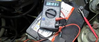
Let's say we need to measure the DC voltage on a battery from some electronic device (I'll take a video camera battery).
1. We carefully study the inscriptions on the battery, we see that the battery voltage is 7.4 volts.
2. We set the measurement limit to be greater than this voltage, but preferably close to this value, then the measurements will be more accurate.
For our example, the measurement limit is 20 volts.
Still, when measuring voltage, for example in circuits, I advise you to set the limit higher than the supply voltage of the circuit, so as not to cause the device to fail.
3. Connect the multimeter to the battery terminals (or parallel to the area where you measure the voltage).
— a black probe, one end to the COM socket of the multimeter, the other to the minus of the measured voltage source;
- red probe to the VΩmA socket and to the plus of the measured voltage source.
4. Read the DC voltage value from the LCD indicator.
Note: if you do not know the approximate value of the measured voltage value, then the measurement must begin by setting the highest limit, that is, for M-831 - 600 volts, and successively approach the limit closest to the measured voltage value.
Purpose of a digital multimeter
The 8ХХ series (830B, 830ВZ, 830C, 831, 832, 833, 838, etc. depending on the manufacturer) is intended for use in the field, laboratories, workshops and households. The multimeter, depending on the model, allows you to make the following measurements:
- measuring direct current - measuring direct voltage - measuring alternating voltage - measuring electrical resistance - checking diodes and transistors - checking circuit integrity (audio continuity) - measuring temperature - generating 50Hz signals (square wave).
How to use these measuring devices
How to use the most common multimeter DT 830B
Working with this model involves the following types of measurements:
- Current Measurement: This device can only measure DC current.
To do this, the probes included in the “COM” and “VΩmA” sockets are connected to the circuit in series with the load. If the current is more than 0.2 A, switch the “VΩmA” probe to the “10A” socket. Set the limit switch to the required position. To measure alternating current, you must use a device like DT-9202A/9208A. The device cannot measure current strength above 10A. For these purposes, use a model with a current clamp, such as the Mastech MY-68 model. - Voltage measurement: The device can measure DC and AC voltage values. To do this, the probes are connected to the “COM” and “VΩmA” sockets, and the switch selects the type of voltage DCV - constant, ACV - alternating, and the required limit. How to determine the polarity of the voltage: When connecting the black probe to the “COM” connector, the red one to the “VΩmA” connector, and the other ends to the “minus” and “plus” respectively, the readings on the device indicator will be without the “-” (minus) sign.
- Resistance measurement: the switch is set to the “Ω” position at the required measurement limit. The DT-830B meter allows you to control this parameter within the range of 200 Ohm - 2 MOhm with an accuracy of 1%
- How to use testers DT-832, DT-838 and others in this series: exactly the same as model 830
- Multimeters M-830 .. M-838 are complete analogues of the devices described above. In addition, M 838 is equipped with a thermocouple for measuring temperatures in the range of 20 .. 300 degrees C
I bought this device for myself the other day, I’m going to learn the basics of electronics. I didn’t find a lot of information about it and how to use it! If there are any errors or additions, please write in the comments.
Even from the packaging it is clear that this is China. The font is very specific.
The device itself
And come to him.
Where to go FAQ
This multimeter can measure the following parameters: - alternating and direct voltage; - direct current; - active resistance; - direct current; - checks diodes and transistors. As you can see, the variety of parameters is not very large, but for repairs at home or in the car enough. For safety reasons, when taking measurements, I recommend installing a temporary plug on the 10A hole. There is a shunt (a piece of thick wire), which can lead to unexpected consequences if switched on incorrectly, say, to measure a voltage of 220V. Top clockwise: - DCV is a measurement of constant voltage values from 20 mV to 1000; - OFF - power off; - ACV - measurement of variable quantities up to 750 V. ; - DCA - meas. current strength in constant voltage. up to 10 A; - hFe for checking transistors; - continuity testing; - resistance measurement.
One black wire to the COM connector, the second, red to V omega mA for measurement. voltage resistance and current The topmost connector for measuring DC voltage
Multimeter connection diagrams.
The DT-838 Digital Multimeter is a good option for home use. It is small in size, highly reliable and simple in design.
Description of the device
A digital multimeter is a portable, universal measuring instrument for measuring parameters of electrical circuits. The device is equipped with a 3.5-digit indicator and has an autonomous battery power supply.
Measurement method - double integration ADC with automatic zero correction, automatic polarity detection and overload indication. Designed for use in field conditions, laboratories, workshops and households.
The multimeter is equipped with overload protection at all measurement ranges and provides low battery indication. Features an automatic power-off feature to extend battery life.
Some functional features
• Switch of operating modes and limits. • High sensitivity - 100 µV. • Automatic overload indication - “1”. • Automatic detection of DC current or voltage polarity. • Resistance measurement from 0.1 Ohm to 2 MOhm. • Testing diodes with direct stable current 0.8 mA. • Measurement of h21E transistors at Ib=100 µA.
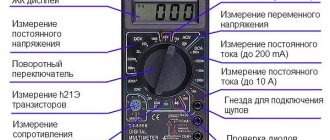
This table shows the functions of the multimeter:
| M832 | M833 | M838 | |||
| DCV (DC Voltage) | + | + | + | + | + |
| ACV (alternating current voltage) | + | + | + | + | + |
| DCA (DC Current) | + | + | + | + | + |
| Ω | + | + | + | + | |
| + | + | + | + | + | |
| + | + | + | + | ||
| hFE | + | + | + | ||
| Square wave generator | 50 Hz | 1000Hz | |||
| TEMP | + |
..
Multimeter dt830b instructions for use
A multimeter is one of the inexpensive measuring instruments that is used by both professionals and amateurs who repair home wiring and electrical appliances.
Without it, any electrician feels like he has no hands. Previously, three different instruments were required to measure voltage, current, and resistance. Now all this can be measured using one universal device. Using a digital multimeter is very easy. The main two rules to remember:
- ⚡where to properly connect measuring probes
- ⚡in what position should the switch be set to measure different quantities?
Specifications
The error is defined as ±(reading + number of least significant units). The measurement accuracy is guaranteed for 1 year, under external conditions of air temperature from 18 to 28°C and relative humidity not exceeding 75%.
General characteristics
• Maximum display reading: number 1999 with automatic polarity detection. • Indication method: LCD display • Measurement method: double integration ADC. • Measurement time: 2-3 measurements per second. • Overload indicator: “1” in the most significant digit on the LCD display indicator. • Maximum common mode voltage: 500V AC/DC. eff. • Low battery indicator: symbol on the LCD display. • Polarity indicator: “-” sign for negative polarity (Automatic detection of DC current or voltage polarity). • High sensitivity - 100 µV. • Resistance measurement from 0.1 Ohm to 2 MOhm. • Testing diodes with direct stable current 0.8 mA. • Measurement of h21E transistors at Ib=100µA. • Overcurrent protection: 500 mA/250 V fuse. • “10 A” input without fuse. • There is no overload protection when measuring resistance and voltage in all ranges. • Guaranteed accuracy temperature: 23°С ±5°С • Temperature range Operation: 0°С +40°С, Storage: -10°С +50°С • Safety category according to GOST R 52319 (IEC 61010-1): CAT II 600 B • Housing insulation: double, class 2. • Degree of protection according to GOST 14254: IP20. • Operating temperature: from 0 to plus 40 °C, with relative humidity not exceeding 80%. • Altitude above sea level up to 2000 meters. • Supply voltage: 9 V. Battery type “KRONA” (NEDA1604, 6F22). • Dimensions, mm: 126x70x24. • Weight: 150 g (with battery). • Accessories: Instructions, test leads, box
Constant pressure.
| LIMIT | PERMISSION | ACCURACY |
| 200 mV | 100 µV | ±0.25%±2 units. accounts |
| 2000 mV | 1 mV | ±0.5%±2 units. accounts |
| 20 V | 10 mV | ±0.5%±2 units. accounts |
| 200 V | 100 mV | ±0.5%±2 units. accounts |
| 1000 V | 1 V | ±0.5%±2 units. accounts |
Input impedance: 10 MOhm at all limits. Overload protection: 200 V eff. at the limit of 200 mV and 1000 V DC. or 750 V eff. AC at other limits
AC voltage.
| LIMIT | PERMISSION | ACCURACY |
| 200 V | 100 mV | ±1.2%±10 units. accounts |
| 750 V | 1 V | ±1.2%±10 units. accounts |
Input impedance: 10 MOhm at all limits. Frequency range: 40Hz - 400Hz. Overload protection: 1000 VDC or 750 V eff. AC at all limits. Calibration: Average (rms sine wave).
D.C.
| LIMIT | PERMISSION | ACCURACY |
| 2000 µA | 1 µA | ±1%±2 units accounts |
| 20 mA | 10 µA | ±1%±2 units accounts |
| 200 mA | 100 µA | ±1.2%±2 units. accounts |
| 10 A | 10 mA | ±2%±2 units accounts |
Overload protection: 200 mA 250 V - fuse, 10 A limit without fuse. Voltage drop: 200 mV.
Resistance.
| LIMIT | PERMISSION | ACCURACY |
| 200 Ohm | 0.1 ohm | ±0.8%±2 units. accounts |
| 2000Ohm | 1 ohm | ±0.8%±2 units. accounts |
| 20 KOhm | 10 ohm | ±0.8%±2 units. accounts |
| 200 KOhm | 100 Ohm | ±0.8%±2 units. accounts |
| 2000 KOhm | 1KOhm | ±1%±2 units accounts |
Maximum voltage on open probes: 2.8 V. Overload protection: 15 sec. maximum 220V at all limits.
…
Audible dial (only in models DT-830C, DT-831, DT-832, DT-838)
Built-in buzzer sounds if resistance is less than 1kOhm
Overload protection: 15 sec. 220V maximum, a signal sounds.
Temperature measurement (DT-830C, DT-838 only)
| LIMIT | PERMISSION | ACCURACY |
| from -20 °C | 1 °C | ±3°С±2 units (up to 150°С) |
| up to +1370 °С | ±3% (above 150 °C) |
Safe and correct operation of the multimeter
Working with electrical devices and networks must be safe. This rule also applies to the procedure for ringing conductors with a multimeter. Let us highlight the main recommendations that must be followed before and during work:
- First of all, the circuit must be completely de-energized by turning off the machine in the switchboard and removing the batteries (if the object in question is an electronic device).
- The capacitors in the circuit must be discharged by short-circuiting. Otherwise, during measuring work, the multimeter may fail.
- For convenience when making measurements, it is recommended to use special tips (“crocodiles”) at the ends of the measuring wires. These devices create reliable contact with the conductor being tested and, at the same time, free your hands.
- When trying to fix the probe, it is not recommended to touch the bare wires and the tip of the probe with your fingers. Otherwise, the results obtained may be incorrect.
Multimeter Guide
1. Check the 9V battery by turning on the device. If the battery is low, [- +] will appear on the display. If you need to replace the battery, see the “Device Care” section.
2. Sign "!" next to the device sockets warns that input currents and voltages should not exceed the specified values. This is done to prevent damage to the device circuitry.
3. Before measurement, the limit switch must be set to the required measurement range.
4. If the limit of the current or voltage to be measured is not known in advance, set the limit switch to maximum and then switch down as necessary.
5. When “1” (overload) appears on the display, you must switch to the upper measurement limit.
DC voltage measurement
1. Insert the red probe into the “V,Ω,mA” socket and the black one into the “COM” socket
2. Set the limit switch to the V= position and connect the ends of the probes to the voltage source being measured. The polarity of the voltage on the display will correspond to the polarity of the voltage on the red probe.
Comment
Built-in buzzer sounds if resistance is less than 1kOhm
Comment
Do not connect the device to a voltage exceeding 1000V. Indication is also possible at high voltages, but there is a risk of damage to the device circuit.
AC voltage measurement
1. Insert the red probe into the “V,Ω,mA” socket and the black one into the “COM” socket
2. Set the limit switch to the V= position and connect the ends of the probes to the voltage source being measured. The polarity of the voltage on the display will correspond to the polarity of the voltage on the red probe.
Comment
Do not connect the device to a voltage exceeding 1000V. Indication is also possible at high voltages, but there is a risk of damage to the device circuit.
DC current measurement
1. Insert the red probe into the “V,Ω,mA” socket and the black one into the “COM” socket. Connect the black wire to the COM connector, and the red wire to the mA connector for currents up to 200mA. For currents up to a maximum of 10A, connect the red probe to the 20A socket.
2. Set the limit switch to the A= position and connect the ends of the probes in series with the load. The polarity of the current on the display will correspond to the polarity on the red probe.
Comment
The maximum input current is 200mA or 20A depending on the socket used. Exceeding the limits will cause the fuse to burn out, requiring replacement. The fuse should be replaced with a similar one for a current of no more than 200 mA. Failure to comply with these requirements may result in damage to the circuit. Input 20A is not protected. Maximum voltage drop 200mV.
….
Resistance measurement
1. Insert the red probe into the “V,Ω” socket and the black one into the “COM” socket.
2. Set the function switch to the required range and connect the ends of the probes to the resistance being measured.
Note 1.
If the value of the measured resistance exceeds the maximum value of the ranges on which the measurement is made, the indicator will display “1”.
Select a larger measurement range. For resistances of 1 MΩ and higher, the readings take a few seconds to settle. This is normal for measuring large resistances. Note 1.
When the circuit is open, the display will indicate “1”.
3. When changing resistances in the circuit, make sure that the circuit is de-energized and all capacitors are completely discharged.
4. The open circuit voltage at the 200M limit is 3V. When the ends are short-circuited at this limit, the display shows 1.0+-0.1 MOhm, this is normal. When measuring a resistance of 10 MΩ, the display will show 11 MΩ; when changing a resistance of 100 MΩ, the display will show 101 MΩ. 1.0 (+-0.1) is a constant that must be subtracted from the reading.
Checking diodes and sound continuity
1. Connect the red wire to the “V,Ω” connector and the black wire to the “COM” connector. (The polarity of red will be “+”)
2. Set the range switch to the “—|>|—” limit and connect the probes to the diode being measured (red probe to the anode and black probe to the cathode of the diode being tested), the display will show the forward voltage drop across the diode. If the diode is turned on in reverse, the number “1” will be displayed.
3. Connect the probes to two points of the circuit under test. If the resistance is less than 5 Ohms, a signal will sound.
Measuring h FE transistor
1. Set the function switch to h FE band.
2. Determine the type of transistor: “NPN” or “PNP” and find the emitter, base and collector terminals. Insert the leads into the corresponding holes in the socket on the front panel.
3. The display will show the h FE value at a base current of 10 μA and a collector-emitter voltage of 2.8 V.
Signal generator 5V 50Hz (Mod. DT-832 only)
In this mode, a 5V (internal resistance 50kOhm) 50Hz rectangular signal appears at the output probes of the device connected to the VΩmA” and “COM” sockets of the device.
The output voltage will be approximately 5V peak-to-peak, DC, so a decoupling capacitor may be needed.
Temperature measurement
1.Set the function switch to the TEMP range; the housing temperature will be displayed on the display with the °C sign.
2. Connect a type K thermocouple to the “COM” and “V,Ω,mA” sockets.
3. Touch the object being tested with the thermocouple.
4. Read the temperature on the display in °C.
Operating modes
The desired operating mode is set by the switch by placing its handle opposite the corresponding sector:
- DCV. Additionally divided into five ranges. This sector is intended for measuring DC voltage in the range 0-500V. Maximum voltage occurs infrequently, for example, during TV repair. When the switch is set to 500V, an HV warning icon will appear in the upper left corner of the display to indicate the maximum level and the need for attention and caution. If the voltage value is not known in advance, switching is performed from the maximum position with a gradual transition to lower values. Failure to comply with this condition may lead to inaccurate readings or failure of the device.
- ACV. Designed for measuring alternating voltage. The sector is divided into two parts - 200 and 500V. When using the 220-380V range you need to be extremely careful. The procedure is the same as in the previous constant voltage sector.
- DCA. This sector performs the function of a milliammeter and is intended for measuring small direct currents. It is not recommended to use this sector unless necessary, and caution should be used when measuring large currents. In this case, you need to ring the chain for no longer than a few seconds.
- hFE. The sector performs continuity measurements of transistors and checks for breakdown or breakage. Elements are tested regardless of their conductivity. The legs of the transistors must be placed in the appropriate sockets, as indicated on the special socket.
- DIODE sector. When the diode is working properly, the voltage drop in the forward direction is shown in the range of 400-700 mV. For the reverse direction, infinity is used. If the diode is faulty, then a value close to zero means a breakdown, and one close to infinity means a break.
- OM sector. Used for resistance measurements. The measurement range is in the range of 200-2000000 Ohms. You should take into account the errors of the Chinese multimeter and its too high sensitivity when making accurate measurements. It is imperative to take into account the resistance that occurs when the probes are connected to each other. This is especially true when measuring resistances that are too small.
Caring for the device
Attention
In case of violation of the operating rules established by the manufacturer, the protection used in this device may deteriorate.
If malfunctions or errors occur in the operation of the multimeter, stop using it immediately. Checking the operation and repairing the device must be carried out in specialized workshops.
Wipe the multimeter with a soft cloth; do not use abrasives or solvents for cleaning. The electronic circuit of the multimeter does not need to be cleaned.
Battery Replacement
If the low battery symbol appears on the display, the battery must be replaced. To replace the battery, remove the screws on the back cover of the multimeter. Remove the back cover from the multimeter body. The battery and fuse are replaced with the power turned off and the probes disconnected from the device.
Remove the old battery and install a new one that meets the specification: 9V CROWN type (NEDA1604, 6F22). Replace the case back cover and tighten the screws. When installing a new battery, ensure correct polarity.
Replacing the fuse
The fuse fails only in the event of a significant and prolonged overload of the device due to the incorrect selection of measurement ranges.
To replace the fuse, remove the back cover from the multimeter, as when replacing the battery, and replace the fuse with a new fuse corresponding to the 0.5 A/250 V type. Close the case.
ATTENTION! To prevent fire, use fuses with a current/voltage rating similar to the current/voltage rating of the fuse installed at the factory.
Classification of multimeters
Multimeter mastech m890c+
There are two main groups of testing instruments (multimeters). Some of them are called analog. A multimeter of this type is distinguished by the presence of a dial with a scale. Readings are taken visually when the arrow, deviating from the “zero” position, points to specific numbers. Such systems are already outdated. Therefore, everything that will be discussed further concerns a new type of devices - electronic. It’s more convenient to work with them, there are more possibilities, the readings are accurate, the error is smaller.
How to use an analog type tester is described in another instruction. Nowadays they are rarely used, because when taking readings, for example, voltage, the degree of error is too great. Initially the measurements are plausible, but are shown with deviation. But here we need to add the human factor, when the eye does not always catch the minimum deviation of the arrow. Digital devices are not afraid of vibration. The readings do not depend on mechanical vibrations. The indicator clearly indicates the value of the measured parameter.
Transportation and storage rules
The product can be transported in any position by any type of transport. Store in a heated, ventilated area at an air temperature of 0 to +40°C and air humidity up to 80%.
When storing after use, the following recommendations must be observed: - disconnect the probes from the multimeter, - make sure that the multimeter and accessories are dry, - if you are not going to use the multimeter for a long time, remove the battery, otherwise it may leak and damage the device.
The storage room should be free of dust, acid and alkali vapors that cause corrosion.
How to use the DT-830B multimeter
There are two points to learn when using a DT multimeter:
- where to connect the probes;
- what position of the selector should be to measure the required value for each specific testing purpose;
The user must know the relationship between the parameters of the two listed items, and this will be completely sufficient for technically correct operation. But besides this, you also need to know how to interpret the readings.
Most tester breakdowns are associated with setting the selector to a position that does not correspond to the values of the measurements being taken.
The inscriptions on the segments with graduation ranges mean the following:
Connecting the probes
There are 2 probes and 3 sockets for them
It is important to connect them correctly when measuring certain electrical parameters, otherwise the device may burn out
The black probe is connected to the COM socket (translated as “common”). For red, depending on the testing needs, there are 2 connectors: 10ADC - measure large currents of 200 mA...10 A. VΩmA connector - for all other tests, for voltage, current up to 200 mA, for resistance, continuity.
Disposal
To prevent environmental pollution, this device must not be disposed of as household waste. The consumer is obliged to hand over all electrical and electronic devices, regardless of whether they contain harmful substances, to specialized collection points to ensure their correct disposal and recycling. Remove the batteries before disposing of the device. You can hand over the batteries to specialized collection points at your place of residence that collect this type of waste.
Device information
The multifunctional tester is easy to use and universal. The model is suitable for work at home, but it has all the features of a professional tool. The device includes measuring probes, a tool for self-diagnosis and a large scale of indicators. The multimeter receives power from a special 9 W power source. The manufacturer has provided only one battery in the set.
The device looks like standard testers, but has several significant differences. The data is presented in digital form, and the device itself can operate with several parameters. All internal elements are enclosed in a reliable housing. The central place on the surface is occupied by a switch. The main advantages of the multimeter:
- performance;
- portability;
- ergonomics.
The device is easy to operate thanks to the massive handle with twenty positions. Around it there are designations of types of work, which is useful for inexperienced users. Data about the parameter being measured is displayed on the digital LCD screen.
How to check wire continuity in resistance detection mode
In multimeters that do not have a continuity function, checking the integrity of the wire can be done in the resistance measurement mode.
In this case, the probes are connected in the same way as during dialing, and the device is set to resistance determination mode ( Ω ).
You need to start measuring at the very minimum threshold of the instrument scale - for example, 200 Ohms. All actions are the same as when calling. You just need to monitor the readings of the device. If the wire is intact, the display will show its resistance value. If there is a break, then the resistance will not be displayed (OL - overload condition).