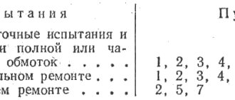
May 26, 2016
engine management Texas Instruments article
The range of semiconductor components manufactured by Texas Instruments includes a wide range of driver chips for controlling all types of electric motors , which, as they improve, are increasingly used in a wide variety of equipment. The company offers solutions for creating drives operating in a wide range of currents and voltages, ensuring reliable and convenient operation of brushed , brushless and stepper motors with a full range of protections for current, voltage and temperature.
Electric motors are widely used in the modern high-tech way of life. This type of electromechanical drive is still one of the most common and in demand. Electric motors for various purposes are one of the main components of any production; they are widely used in office and home appliances, in monitoring and control systems for buildings and facilities. Electric motors are very widespread in modern transport. An even more exciting future lies ahead for electric motors in electric vehicles and robots.
With the development of technology, traditional engines are being improved and are finding new applications. Modern high-precision machine tools and robotics are unthinkable without electric motors with intelligent control systems. On land, in the air and under water, electric motors remain a widely used converter of electrical energy into mechanical energy.
Types of electric motors, control methods and difficulties encountered
First created in 1834 by the Russian scientist Jacobi, the converter of electrical energy into rotational motion was called an electric motor. Since then, it has been seriously improved - many new options have appeared, but the principles of electromagnetism used in its creation are still the basis of all modifications of modern electric motors.
A conductor with a current passing through it (Figure 1) creates a magnetic field around itself, the intensity (magnetic induction) of which is proportional to the number of turns, in the case of using a coil (N), and the magnitude of the current passing through it (I), where B is the magnetic vector induction, K – magnetic constant, N – number of turns, I – current strength.
Rice. 1. Electromagnetism is the basis of the operation of an electric motor
Changing the direction of the current also affects the direction of the magnetic field of the conductor.
In this case, a current-carrying conductor placed in an external magnetic field is acted upon by the Lorentz force, causing it to rotate. The direction of rotation is easily determined using the well-known right-hand rule for a current-carrying conductor in a magnetic field (Figure 2). The force (F) acting on a conductor in a magnetic field is equal to the product of the current strength (I) in the conductor by the field magnetic induction vector (B) and the length of the conductor (L). F = LIB.
Rice. 2. Movement of a conductor with current in a magnetic field (Lorentz force)
Selecting a driver for the MT-1703HD200AW stepper motor. Comparison between DRV8825 and A4988
The driver is an intermediary between the stepper motor (SM) and the source of control actions. With its help, the motor motor is controlled with the possibility of precise positioning of the motor motor shaft. The main task of the driver is to supply the appropriate voltage to the windings of the stepper motor, depending on the input signal. [1]
The task is to experimentally determine the most optimal driver for the SD MT-1703HD200AW. It is necessary to determine the limiting frequencies at which a smooth, stable start and rotation of the motor occurs, as well as stall frequencies at which the motor stops rotating stably. The cutoff frequencies are recommended for creating devices based on the SD and driver data.
The stepper motor is controlled through the driver inputs “ENABLE”, “MS1”, “MS2”, “MS3”, “STEP” and “DIR”.
– ENABLE — is responsible for enabling the driver;
– “MS1”, “MS2”, “MS3” - are responsible for switching microstepping modes.
– DIR — is responsible for the direction of rotation of the motor;
– STEP—responsible for receiving rotation pulses.
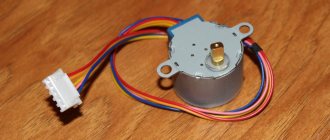
The type of stepper motor is the most important factor when choosing a stepper motor driver. In our study we will use a bipolar stepper motor MT-1703HD200AW.
It is worth paying attention to the current strength that the driver can provide. You need to choose a driver that will provide a current not less than the phase current of the selected stepper motor. [2]
The supply voltage affects the dynamics, vibrations, heating of the motor and driver.
The presence of microstepping modes ensures smooth operation of the motor at low speeds and high resolution of the positioning angle. Using the microstep mode reduces the resonant effect of the stepper motor. When this occurs, the motor begins to vibrate and lose torque, until the shaft stops completely.
For this work, two drivers DRV8825 and A4988 were selected. The A4988 driver was created by Allegro, and the DRV8825 driver was created by TI (Texas Instruments Inc.). The pinout and interface of these modules are almost the same. This allows you to replace drivers in devices without changing the board layout, but with the possible editing of the software control code.
Rice. 1. Stepper motor driver A4988 and DRV8825
The main differences between the DRV8825 and A4988 drivers:
The DRV8825 driver has a FAULT output, but the A4988 driver does not have it. FAULT—protection alarm output. At this output, a logical “0” signal indicates that the field-effect transistors of the H-bridge were turned off as a result of overcurrent protection or due to overheating.
The SLEEP pin on the DRV8825 is not connected to the power supply by default, like on the A4988, but it is connected on the board to the FAULT pin via a 10k resistor.
Different position of the potentiometer regulating the current limit. Different ratio of limit current to reference voltage.
The driver on the DRV8825 supports 1/32-step microstepping. The A4988 has a maximum of 1/16-step. The 1/16-step input on the A4988 corresponds to the 1/32-step input on the DRV8825. The remaining driver switching modes are the same.
DRV8825 supports higher supply voltage 8.2..45V, and A4988 8...35V. This means that the DRV8825 driver is safer when operating at high voltages and is less susceptible to inductive-capacitive voltage surges.
The DRV8825 driver provides current up to 1.5A per phase without a radiator, and the A4988 1A.
The A4988 driver is cheaper than the DRV8825 driver.
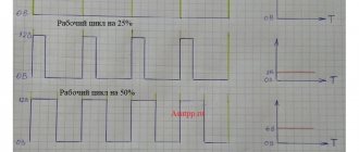
In the table - 1 and 2, with a driver supply voltage of 4.5V, we accelerate the motor smoothly from a stable start to the stall frequency, for various microsteps. We determined the limit value of the frequency at which the stepper motor starts stably.
Table 1
Frequencies of starting and stalling of stepper motor with A4988 driver
| Microstep assignment | Optimal crossover frequency at 4.5 V | Motor start limit value | |
| launch | limit | ||
| Full step | 850 Hz / 255 rpm | 9000 Hz / 2700 rpm | 1000 Hz |
| Half step | 1500 Hz / 450 rpm | 2560 Hz / 768 rpm | 2500 Hz |
| Quarter step | 3050 Hz / 915 rpm | 31500 Hz / 9450 rpm | 4500 Hz |
| One eighth step | 6200 Hz / 1860 rpm | 91100 Hz / 27330 rpm | 7900 Hz |
| One sixteenth of a step | 12500 Hz / 3750 rpm | 192300 Hz / 57690 rpm | 15300 Hz |
table 2
Frequencies of starting and stalling of stepper motor with driver DRV 8825
| Microstep assignment | Optimal crossover frequency at 4.5 V | Motor start limit value | |
| launch | limit | ||
| Full step | 700 Hz / 210 rpm | 1780 Hz / 534 rpm | 1300 Hz |
| Half step | 1200 Hz / 180 rpm | 10400 Hz / 1560 rpm | 2800 Hz |
| Quarter step | 2600 Hz / 195 rpm | 67000 Hz / 5025 rpm | 5700 Hz |
| One eighth step | 5100 Hz / 191.25 rpm | 93000 Hz / 3100 rpm | 13400 Hz |
| One sixteenth of a step | 10500 Hz / 196.875 rpm | 389000 Hz / 7293.75 rpm | 26700 Hz |
| One thirty-second step | 19000 Hz / 178.125 rpm | 463000 Hz / 4340.625 rpm | 55000 Hz |
From Tables 1 and 2 it can be seen that the A4988 driver begins to operate stably at lower frequencies than the DRV8825 driver, but the stall frequency of the DRV8825 driver is significantly higher at steps of 1/8 and 1/16, which makes the DRV8825 driver more attractive when operating MT step motors -1703HD200AW at low speeds.
Literature:
- Pushkarev, O. “The first step” of a stepper motor / O. Pushkarev //Modern electronics. - 2004. - No. 1. - P. 46–47.
- Vychuzhanin, V. Control of a stepper motor using FPGA / V. Vychuzhanin // Components and technologies. — 2004. – No. 3. — P. 96–98.
Brushed motors
Brushed DC motors (BDC or BDC, in TI terminology) are among the most common electromagnetic rotation mechanisms today.
In the magnetic field of a stator assembled from permanent magnets, a multi-section rotor with coils rotates, which are connected in pairs and alternately through switched collector lamellas on the rotor axis (Figure 3). The selection of a pair of activated coils is carried out on the basis of Lorentz's law in accordance with Gimlet's rule. The current source is always connected to coils whose magnetic field lines are shifted at an angle close to 90° relative to the stator magnetic field.
Rice. 3. Operating principle of a commutator motor (BDC)
Electric motors of this type often use a permanent magnet stator. They make it easy to adjust the rotation speed and are inexpensive.
A variant of a 2-winding electric motor of this type is also widely used, but with a stator winding instead of a permanent magnet. Such models have a large starting torque and can operate not only on direct current, but also on alternating current. Electric motors of this type are almost universally used in various household appliances.
The disadvantages of this BDC design include wear of the brush-commutator assembly during operation. In addition, due to sparking during commutation of individual rotor windings, an increased level of electromagnetic interference is observed, which does not allow the use of such motors in explosive environments.
A feature of BDC engines is also increased heating of the rotor, the cooling of which is difficult due to the design features of the engine.
Advantages of commutator motors:
- low cost;
- simple control system;
- 2-winding brushed motors with high torque and capable of operating on DC and AC.
Features of operation of commutator motors:
- brushes require periodic maintenance and reduce engine reliability;
- during the switching process, electrical sparks and electromagnetic interference occur;
- It is difficult to remove heat from an overheating rotor.
Simple driver circuit for a unipolar stepper motor
unipolar stepper motor driver circuit described in this article implements the following tasks: • controlling a 4-phase unipolar stepper motor. • provides smooth adjustment of rotation speed and change of direction of rotation. • performs the function of stopping the engine.
Electric soldering iron with temperature control
Power: 60/80 W, temperature: 200'C-450'C, quality…
More details
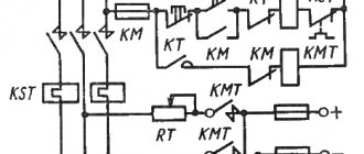
Below is a schematic diagram of a stepper motor driver. The driver is built using three 4000 series microcircuits and four power MOSFET transistors.
The circuit is clocked by a rectangular pulse generator built on 2I-NOT logic elements with a Schmitt trigger at the output. The operating frequency of the generator is determined by the total resistance PR1 + R2 and the capacitance of capacitor C1, and can be changed over a wide range using potentiometer PR1.
A fragment of the circuit on the EXOR elements and the JK flip-flop creates a modulo 4 counter, with high-level clocks. Switch SB1 (JP1) is designed to change the direction of operation of the counter, and, consequently, to change the direction of rotation of the stepper motor. Using switch SB2 (JP2) you can start and stop the engine.
The coils of a 4-phase stepper motor are controlled using four MOSFET transistors (VT1...VT4). The use of high power transistors of the BUZ11 type in this circuit is a solution that guarantees proper operation of the high power motor.
Below are the waveforms at connector X2, to which the stepper motor windings are connected.
The driver is assembled on a printed circuit board, the picture of which is shown below. Installation should begin with the installation of resistors, sockets for microcircuits and finish with connectors and power transistors.
Professional digital oscilloscope
Number of channels: 1, screen size: 2.4 inches, resolution...
More details
JP1 and JP2 have the same function as push button SB1 and SB2, so you can connect buttons to them and take them off the board. The printed circuit board is designed in such a way that you can install transistors on a common heatsink, after insulating them with mica or silicone gaskets.
After assembly, you must carefully check the board for short circuits in the tracks. A driver assembled from serviceable parts does not require configuration and starts working immediately.
It is worth mentioning the method of connecting the power supply and motor windings to the driver board. If the control circuit and motor are powered with the same voltage, which is in the range from 5...15 V, and the current consumption does not exceed 1 A, then it is necessary to install jumper JP3 and apply power to the VDD connector.
If the power parameters of the stepper motor are not within the supply voltage of the driver circuit, then it is necessary to remove jumper JP3, and supply a supply voltage of 5...15 V to the VDD connector, and supply power to the X2 connector in accordance with the parameters of the stepper motor.
PCB drawing (8.5 KiB, downloads: 2,060)
Brushless motors
Somewhat less common among DC motors are brushless design models (BrushLess DC or BLDC), which use a rotor with permanent magnets that rotate between stator electromagnets (Figure 4). Current switching here is performed electronically. Switching the windings of the stator electromagnets causes the rotor's magnetic field to follow its field.
Rice. 4. Operating principle of brushless DC motor (BLDC)
The current rotor position is usually monitored by encoders or a Hall effect sensor, or technology is used to measure the back-EMF voltage on the windings without using a separate rotor position sensor (SensorLess) in this case.
Current switching of the stator windings is performed using electronic switches (valves). This is why brushless BLDC motors are often called "valve-type" motors. The order of connection of a pair of motor windings depends on the current position of the rotor.
The operating principle of BLDC is based on the fact that the controller switches the stator windings so that the stator magnetic field vector is always shifted by an angle close to 90° or -90° relative to the rotor magnetic field vector. The magnetic field rotating during switching causes the rotor with permanent magnets to move after it.
When using a three-phase control signal, only two pairs of windings are always connected to the current source, and one is disconnected. As a result, a combination of six states is used sequentially (Figure 5).
Rice. 5. Phase rotation when rotating BLDC
Electric motors without rotor position sensors are characterized by increased manufacturability of the manufacturing process and lower cost. This design simplifies the sealing of external connected terminals.
Hall sensors can be used as rotor speed and position sensors in BLDC, which are low cost, but also have a fairly low resolution. Increased resolution is provided by rotating transformers (resolvers). They are expensive and require the use of a DAC, since their output signal is sinusoidal. Optical sensors have high resolution, but reduced reliability. Figure 6 shows the output signals of different types of sensors when the engine rotor rotates.
Rice. 6. Rotor position sensors for electric motors
So, when I was thinking about a driver for field workers for bipolars, I didn’t think that the topic would arouse such interest and that I would have to write a short article on assembly and configuration. Here the driver will be considered as a separate block. Because I use block construction. Those. three drivers, interface board, power supply. Firstly, when one driver fails, the driver is simply replaced with a spare one, and secondly (and most importantly) modernization is planned, it’s easier for me to remove one driver and install the upgraded version for testing. “Single-payer” is already a development of the topic, and I think Dj_smart will be happy to answer questions about setting up a UPS, and will also complement and correct my work. And now to the point...Point one (those who have filled the board don’t have to read J). After etching, tinning, and drilling, carefully inspect the entire board for jambs. Snot, etched tracks, etc. can seriously ruin the whole buzz. Next we fill the board, first all the jumpers, then resistances, diodes, panels, capacitors and bipolar transistors. I would like to draw special attention to your attention, sorry for... Don’t be lazy before soldering to check the part for serviceability. Dialing sometimes saves you from smoke... I know the color coding of resistors very well, and made fun of me several times, and with a special one. effects. When you use resistors from stashes that have been soldered for years from everything that comes to hand, you forget that when heated, red can turn orange, and orange can turn yellow... We solder in the +5V power wires, step, GND, and Vref control wires. This is roughly what it looks like:
Point two (setting up operating and holding modes). 555 I personally solder into the board, whoever installed the panel means we plug it in, the display unit must be turned off. Trimmers to the middle. We close the step output to general (working mode). We call the +5V circuit and if there is no short, turn on the power. The tester is connected to the Vref control points (well done Dj_smart, he provided it on the board), if the values of the trimmers and the resistance between them correspond to the circuit, then the trimmer is slave. mode, you can adjust the voltage to about 0 - 1V i.e. current 0 – 5A. Let's set it to 1A. Everything is simple here. Rmeas. we have 0.2 Ohm. We need 1A. 0.2x1=0.2V. Those. if we set Vref - 0.2V, the current in the winding will be 1A. If we need a current in the winding, say 2.5A, then Vref = 0.2x2.5 = 0.5V.
In short, we set it to 0.2V.
Now we open the step and general. If all the elements are normal and according to the scheme, then after opening, after about half a second, Vref will decrease by half (if the second trimmer is in the middle). We adjust the hold Vref with it. I have 50 percent. from a worker:
The main thing to pay attention to is the mandatory delay when switching. When the step is closed to general, the operating mode should instantly turn on, and when opened, it should go into hold mode with a delay of 0.5 s. If there is no delay, look for problems, otherwise there will be serious glitches during operation. If it doesn't start, go to the forum topic, don't start fires.
Point three (setting up the display block). The signet is wired for 315-361, like Dj_smarta, there is also a bag, you need to solder somewhere... But in principle, any pair can be soldered there, of ours I tested 502 - 503, 3102 - 3107, everything works, just be careful with the pinout! If everything is soldered correctly and working, then it works without problems. The indication makes a small adjustment to Vref, so after connecting the indication, finally adjust the current to your stepper motor (preferably 70% of the nominal one to start with). J did not take photos of how the LEDs were lit.
Point four, important (297) Turning off the power, plug 297 into its place. We check the installation again, and the piping elements, if everything is OK (if there is any doubt, we check it twice), turn on the power. We check the signal on the first leg with an oscilloscope, it is like this:
Or on the 16th leg, it’s like this:
This means that the shim has started, the lucky ones who have a frequency meter can measure the frequency, it should very approximately correspond to 20 kHz.
ATTENTION!!! It is important!!! Even if the shim does not start, the logical part 297 will work, i.e. when the load is connected, all signals will go... But estimate 24V without a shim at 2 Ohm SD. So it is important to make sure that the chip generator is running.
Point five. Again, turn off the power and insert the IR, solder the field terminals. When using a motor with a winding current of more than 2.5A, it is necessary to place the field switches on the radiator. Please pay attention when soldering diodes, they may differ in marks. I really haven’t come across it (I have a mix of 522 and 1N4148 (analogue), they have the same pinout) But considering that people come across IRs with incorrect operating logic, be careful. We check the power circuits for short circuits and check the installation. I immediately turned on all the power, only instead of the SD I soldered the LEDs connected in parallel in opposite directions:
If they walk, then everything is OK, we cut off the motor, connect it to an LPT or an interface board with optical isolation (as you like) and go crazy.
This description does not pretend to be a bestseller; it can be supplemented and criticized, but only on its merits...
Checking L297 using TM2
In short, the essence of the joke.
Our pulse is about 20 kHz. We won't hear. We assemble a divider by 2 on TM2, at 10 kHz - it will already beep at full blast. Here is the diagram Connecting Pin 3 to Pin 1 of L297. Pin 5 through a 0.01-0.1 uF capacitor to the earphone, the second end of the earphone to ground. Tex... Yes, her nutrition is 14th +5, 7th - mass. Leave the remaining legs free.
[47.38 Kb] (downloads: 1289) diagram and signet from delta24
Discussion in the private part of the forum (regular users only, contact delta24 for access)
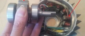
Stepper motors
Stepper motors (SM) have become quite widespread in automation and control systems. They are another type of brushless DC motor. Structurally, motors consist of a stator on which the field windings are located, and a rotor made of magnetic materials. Stepper motors with a magnetic rotor make it possible to provide greater torque and rigid fixation of the rotor when the windings are de-energized.
During rotation, the motor rotor moves in steps under the control of power pulses supplied to the stator windings. Stepper motors are convenient for use in drives of machines and mechanisms operating in start-stop mode. Their range of movement is set by a specific sequence of electrical impulses. Such motors are highly accurate and do not require sensors or feedback circuits. The angle of rotation of the rotor depends on the number of control pulses supplied. The positioning accuracy (step size) depends on the design features of the motor, the connection diagram of the windings and the sequence of control pulses supplied to them.
Depending on the configuration of the winding connection diagram, stepper motors are divided into bipolar and unipolar. A bipolar motor has in each of the two phases a single winding for both poles of the stator, which must be reversed by the driver to change the direction of the magnetic field. A bipolar motor has two windings and, accordingly, four outputs. To control such a stepper motor, a bridge driver or half-bridge circuit with 2-polar power supply is required. With bipolar control, two windings operate simultaneously and the torque is approximately 40% greater. Figure 7 shows the sequence of control signals during rotation of the bipolar motor.
Rice. 7. Sequence of bipolar stepper motor control signals
A unipolar motor uses one winding in each phase with a middle terminal and allows the use of a simpler control circuit with one switch for each of the four half-windings.
Four-winding motors can be used in both bipolar and unipolar configurations.
When current flows through one of the coils, the rotor tends to change position so that the opposite poles of the rotor and stator are positioned opposite each other. To ensure continuous rotation of the rotor, the coils are switched alternately.
In practice, different methods are used to supply power to the four stator windings. Most often, paired connections with full-step or half-step operating modes are used. In full-step mode, a rotor with two poles, rotating in the switchable magnetic field of two pairs of coils, can occupy four positions (Figure 8).
Rice. 8. Full-step motor control mode
The half-step operating mode allows you to obtain double positioning accuracy and eight positions (Figure 9). To implement it, an intermediate step is added with simultaneous powering of all four coils.
Rice. 9. Half-step motor control mode
The microstepping mode allows you to significantly increase the number of intermediate positions and positioning accuracy. The idea of a microstep is to supply a continuous signal resembling a stepped sine wave in shape to the windings of a stepper motor instead of control pulses (Figure 10). In this case, the full step is divided into small microsteps, and the rotation becomes smoother. Microstepping mode allows you to get the most accurate positioning. In addition, in this mode, the vibration of the housing inherent in stepper motors is significantly reduced.
Rice. 10. Motor control in microstep mode
Stepper motor operation
A stepper motor is a multi-winding synchronous brushless motor in which current applied to one of the stator windings causes the rotor to lock. Sequential activation of the motor windings causes angular movements (steps) of the rotor.
Stepper motors have fairly high reliability and a long service life. As the engine speed increases, the rotating torque decreases. Stepper motors produce more vibration along with other types of motors because the discrete step tends to grab the rotor from one position to another. This makes the stepper motor noisier. The vibration can be strong, which can cause the motor to lose torque because the shaft is in a magnetic field and behaves like a spring. Stepper motors operate without feedback, meaning they do not use encoders or resolvers to determine position.
There are four main types of stepper motors:
- Permanent Magnet Stepper Motors
- Hybrid stepper motor
- Variable reluctance motors
- Bipolar and unipolar stepper motors
Stepper motors consist of a stator with field windings and a rotor made of soft magnetic or hard magnetic material. Stepper motors with a magnetic rotor allow you to obtain greater torque and provide fixation of the rotor when the windings are de-energized. Depending on the design of the rotor, the following types of stepper motors are distinguished: with permanent magnets (rotor made of hard magnetic material), reluctance (rotor made of soft magnetic material), hybrid. Hybrid motors combine the best features of variable reluctance motors and permanent magnet motors.
In mechanical engineering, high-torque two-phase hybrid stepper motors with angular movement of 1.8°/step (200 steps/revolution) or 0.9°/step (400 steps/revolution) are more common. The accuracy of pitch setting is determined by the quality of machining of the rotor and stator of the electric motor. Stepper electric motors are used in drives of machines and mechanisms operating in start-stop mode or in continuous motion drives, where the control action is set by a sequence of electrical pulses. Unlike servos, stepper drives allow precise positioning without the use of feedback from angle encoders. Stepper motors with permanent magnets can be used as rotation angle sensors due to the generation of EMF on the windings when the rotor rotates.
Traditional solutions for electric motor control
A modern precision DC motor control system includes a microcontroller for data processing and a motor control unit, often called a driver. The driver includes a logic circuit for converting encoded messages into digital control signals, from which analog signals are generated in the Gate Driver block to control power switches based on field-effect transistors (FETs). FETs can be part of the driver or placed in a separate block. In addition, the driver includes power circuit protection circuits and feedback circuits to control engine operation.
Figure 11 shows the block diagram options for the integrated and pre-drivers. Each of the solutions has its own advantages and features. The Pre-Driver has a significantly improved temperature regime and allows you to select external power switches in accordance with the power of the connected engine. A full-featured integrated driver allows you to create more compact control systems, minimizes external connections, but makes it much more difficult to ensure the required temperature conditions.
Rice. 11. Block diagrams of engine control systems
Thus, for the integrated driver TI DRV8312, the maximum operating temperature of individual elements on the board can reach 193°C, while for the preliminary driver DRV8301 this figure does not exceed 37°C.
Rice. 12. Changing the direction of rotation of the commutator motor
One of the most common circuits for switching motor windings is the “H” bridge. The name of the circuit refers to the connection configuration, which looks like the letter “H”. This electronic circuit allows you to easily change the direction of current in the load and, accordingly, the direction of rotation of the rotor. The voltage applied to the windings through the bridge transistors can be either constant or modulated using PWM. The H-bridge is designed, first of all, to change the polarity of the motor power supply - reverse (Figure 12), but also allows you to slow down the rotation by short-circuiting the terminals of the windings (Figure 13).
Rice. 13. Rotation, fast and slow braking modes
The most important characteristic of the power elements of the bridge, which today are often used as field-effect transistors with an insulated gate, is the resistance value of the open channel between the source and drain of the transistor - RDSON. The RDSON value largely determines the thermal characteristics of the unit and energy losses. As the temperature increases, RDSON also increases, and the current and voltage on the windings decrease.
The use of PWM control signals can reduce torque ripple and ensure smoother rotation of the motor rotor. Ideally, the PWM frequency should be higher than 20 kHz to avoid acoustic noise. But as the frequency increases, the losses on the bridge transistors during the switching process increase.
Due to the inductive properties of the load in the form of windings, the shape of the current in it does not correspond to the shape of the applied PWM voltage. After applying a voltage pulse, the current increases gradually, and during pauses the current gradually fades due to the occurrence of back-EMF in the windings. The slope of the current curve, amplitude and frequency of the pulsations affect the performance characteristics of the motor (torque ripple, noise, power, etc.).
To accelerate the attenuation in the windings of electric motors of the current excited by the back-EMF effect, diodes are used in reverse connection, shunting the drain-source transitions of transistors, or the windings are short-circuited through the drain-source transitions of two transistors simultaneously connected in different arms of the bridge. Figure 13 shows three states of the bridge: working, fast braking (Fast Decay) and slow braking (Slow Decay).
And the most effective is considered to be the combined mode (Mixed Decay), in which, during the pause between operating pulses, the diodes that shunt the drain-source of the transistors first operate, and then the transistors in the lower arms of the bridge turn on.
EQUIPMENT TECHNOLOGY DEVELOPMENT
As a rule, the logical signals for controlling the stepper motor are generated by a microcontroller. The resources of modern microcontrollers are quite enough for this even in the most “heavy” mode – microstepping.
To connect stepper motors via low-current logic signals of microcontrollers, signal amplifiers - drivers are needed.
Driver features include:
- ensuring the required current and voltage on the phase windings of the motor;
- winding switching; inclusion;
- shutdown;
- polarity change;
This article is about simple drivers that are sufficient for most applications. There are drivers with much greater capabilities:
- ensuring a rapid increase in current when turned on and a rapid decrease when turned off;
- reducing the current to fix the position of a stopped engine;
- protective functions;
- generation of winding current and voltage for microstepping mode;
- and many others.
The circuitry of such drivers is quite complex, and these functions are not necessary in most applications.
According to the connection diagram, stepper motors are divided into unipolar and bipolar. The drivers for these two engine options are fundamentally different.
- Unipolar stepper motor driver.
- Unipolar stepper motor driver circuit.
- Bipolar stepper motor driver.
- Bipolar stepper motor driver circuit.
- L298N bipolar stepper motor driver.
- Characteristics of the L298N chip in Russian.
- L298N driver connection diagram.
Unipolar stepper motor driver.
Motors with the following winding configurations can operate in unipolar mode.
Let me remind you of the principle of controlling a unipolar stepper motor. Four windings with a common wire connected to one pole of the power source. If the other terminals of the windings are connected in series to the other pole of the source, the motor rotor will rotate.
To switch the windings in this way, only four keys are enough to connect the windings to ground. The switching diagrams for the windings of the two previous engine options look like this.
If you close keys 1, 2, 3, 4 in sequence, the engine rotor will rotate.
Unipolar stepper motor driver circuit.
In practice, switches can be made using bipolar transistors, but it is preferable to use low-threshold MOSFET transistors. I use IRF7341 transistors. These are MOSFET transistors with the following parameters:
- maximum permissible current 4 A;
- maximum voltage 55 V;
- open resistance 0.05 Ohm;
- switching threshold 1 V;
- made in a miniature SO-8 case;
- There are two transistors in the housing.
An extremely convenient option for use in a unipolar stepper motor driver.
- There is no need for key cooling radiators;
- very low voltage drop across an open transistor;
- small sizes;
- only two 8-pin packages for a two-phase stepper motor driver.
It is impossible to create switches with such parameters on bipolar transistors. There are many other options for MOSFET transistors for switches, for example IRF7313 (6 A, 30 V, 0.029 Ohm).
The switch circuit on a MOSFET transistor for one phase looks like this.
The key is controlled directly from the microcontroller by logical levels KMOP or TTL (0 / +5 V). When the control signal is high (+5 V), the switch is open and current flows through the phase winding. The diode bypasses the motor winding in the opposite direction. It is necessary to protect the transistor from self-induction voltage surges when a phase is turned off. To control motors at significant rotation speeds, it is better to use high-frequency diodes, for example, FR207.
Here is a fragment of a diagram for connecting a unipolar stepper motor to a microcontroller.
There is no protection against short circuits in this circuit. Implementing protection significantly complicates the driver. And short circuits in the windings of stepper motors practically never happen. I have not encountered such a phenomenon. And against the backdrop of troubles about a burnt-out expensive engine, replacing the transistor does not look like a problem.
By the way, mechanical jamming of the stepper motor shaft does not cause unacceptable currents in the driver keys and does not require protection.
And this is an image of a controller board for a unipolar stepper motor with a PIC controller from Microchip.
A simple board with an eight-bit PIC18F2520 microcontroller controls:
- two stepper motors with phase current up to 3 A;
- two PWM keys for electromagnets;
- reads the status of 4 sensors;
- exchanges data over the network with the central controller.
This controller is used as part of the stepper motor control system in almost all ROST packaging equipment.
Despite the simplicity of the controller, the following control modes are implemented:
- full-step, one phase per full step;
- full-step, two phases per full step;
- half-step;
- fixing the engine position when stopping.
The advantages of controlling a stepper motor in unipolar mode include:
- simple, cheap, reliable driver.
Disadvantages:
- in unipolar mode the torque is approximately 40% less compared to bipolar mode.
An example of a practical circuit for a simple unipolar stepper motor controller.
An article about connecting a unipolar stepper motor to an Arduino board.
Bipolar stepper motor driver.
Motors with any winding configuration can operate in bipolar mode.
A bipolar motor has one winding for each phase. Usually there are two windings AB and CD. In the first two options, four windings are connected so that two windings are obtained. The windings are connected in turn to the power source in one polarity, then in the other.
The bipolar motor driver must provide complex switching. Each winding:
- connected in direct polarity to the voltage source;
- disconnected from the voltage source;
- connected with opposite polarity.
The switching diagram of one winding of a bipolar motor looks like this.
To provide two polar switchings from one power source, 4 switches are required. When switches 1 and 2 are closed, the winding is connected to the power source in straight polarity. Closing switches 3 and 4 supplies the winding with reverse voltage polarity.
The complexity of the bipolar stepper motor driver is caused not only by the large number of switches (4 keys per winding, 8 keys per motor), but also:
- complex control of the upper keys (1 and 4) from logical signals “tied” to ground;
- problems with through currents when simultaneously opening the keys of one arm (1.3 or 2.4).
Through currents can arise due to different speeds of the lower and upper switches. For example, the lower key has already opened, but the upper key has not had time to close.
Bipolar stepper motor driver circuit.
It is quite difficult to implement a bipolar stepper motor driver circuit using discrete elements. I can show you my circuit that connects a bipolar motor to a unipolar driver. This circuit is used to control bipolar motors from the controller given as an example in the previous chapter.
The scheme is quite simple. The problem of through currents is solved by using 0.22 Ohm resistors in switched circuits. At the moment of commutation of MOSFET transistors, the upper and lower switches are simultaneously open for a short time. These resistors limit the through current. Unfortunately, they also limit the operating current of the motor. Therefore, despite the powerful transistors, a driver according to this circuit can be used for switching currents of no more than 2 A. The circuit does not require diodes to protect against the self-induction emf of the windings, because these diodes are integrated into MOSFET transistors.
It is much more convenient and practical to use integrated bipolar stepper motor drivers. The most common of them is the L298N chip.
L298N bipolar stepper motor driver.
There is practically no description of this microcircuit in Russian. Therefore, I present the parameters of the L298N in sufficient detail, according to the official materials of the manufacturer of this chip - STMicroelectronics (datasheet l298n.pdf).
The L298N is a full bridge driver for driving bidirectional loads up to 2A and 46V.
- The driver is designed to control components with inductive loads such as electromagnets, relays, stepper motors.
- Control signals are TTL compatible levels.
- Two enable inputs make it possible to turn off the load regardless of the input signals of the microcircuit.
- It is possible to connect external current sensors to protect and control the current of each bridge.
- The logic power supply and the L298N load are separated. This allows the load to be supplied with a voltage of a different value than the power supply to the microcircuit.
- The microcircuit has overheating protection at + 70 °C.
The block diagram of the L298N looks like this.
The microcircuit is made in a 15-pin package with the ability to attach a cooling radiator.
L298N pin assignments.
| 1 | Sense A | Resistors are connected between these terminals and the ground - current sensors to monitor the load current. If current control is not used, they are connected to ground. |
| 15 | Sense B | |
| 2 | Out 1 | Bridge A outputs. |
| 3 | Out 2 | |
| 4 | Vs | Load power supply. A low-impedance capacitor of at least 100 nF must be connected between this pin and ground. |
| 5 | In 1 | Bridge control inputs A. TTL compatible levels. |
| 7 | In 2 | |
| 6 | En A | Bridge operation permission inputs. TTL compatible levels. Low signal level prohibits bridge operation. |
| 11 | En B | |
| 8 | GND | General conclusion. |
| 9 | Vss | Power supply for the logical part of the microcircuit (+ 5 V). A low-impedance capacitor of at least 100 nF must be connected between this pin and ground. |
| 10 | In 3 | Bridge control inputs B. TTL compatible levels. |
| 12 | In 4 | |
| 13 | Out 3 | Bridge B outputs. |
| 14 | Out 4 |
Maximum permissible parameters L298N.
| Designation | Parameter | Meaning |
| Vs | Supply voltage | 50 V |
| Vss | Logic supply voltage | 7 V |
| Vi,Ven | Logic input voltage | -0.3…7 V |
| Io | Output current (per channel)
| 3 A 2.5 A 2 A |
| Vsens | Voltage current sensors | -1…2.3 V |
| Ptot | Power dissipation (case temperature 75°C) | 25 W |
| Top | Operating temperature of the crystal | -25…130 °C |
| Tstg | Storage temperature | -40…150 °C |
Parameters for calculating thermal conditions.
| Designation | Parameter | Meaning |
| Tth j-case | Thermal resistance crystal-case | 3 ºC/W |
| Tth j-amb | Thermal resistance crystal-environment | 35 ºC/W |
Electrical characteristics of the L298N driver.
| Designation | Parameter | Meaning |
| Vs | Supply voltage (pin 4) | Vih+2.5 …46 V |
| Vss | Logic power | 4.5…5…7 V |
| Is | Quiescent current consumption (pin 4)
| 13 … 22 mA 50 … 70 mA 4 mA |
| Iss | Quiescent current consumption (pin 9)
| 24 … 36 mA 7 … 12 mA 6 mA |
| Vil | Input voltage low (pins 5, 7, 10, 12, 6, 11) | -0.3…1.5 V |
| Vih | High level input voltage (pins 5, 7, 10, 12, 6, 11) | 2.3…Vss V |
| Iil | Low level input current (pins 5, 7, 10, 12, 6, 11) | -10 µA |
| IIh | High level input current (pins 5, 7, 10, 12, 6, 11) | 30 … 100 µA |
| Vce sat(h) | Upper switch saturation voltage
| 0.95…1.35…1.7 V 2…2.7 V |
| Vce sat(l) | Lower key saturation voltage
| 0.85…1.2…1.6 V 1.7…2.3 V |
| Vce sat | Total voltage drop across public switches
| 1.8 ... 3.2 V 1.8 ... 4.9 V |
| Vsens | Current sensor voltage (pins 1, 15) | -1…2 V |
| Fc | Switching frequency | 25 … 40 kHz |
Connection diagram of a stepper motor to a microcontroller using the L298N driver.
The operation diagram of this circuit in full-step mode looks like this.
If enabling inputs and current sensors are not used, the circuit looks like this.
And here is a fragment of the bipolar stepper motor controller circuit.
In terms of functions, this is an analogue of the controller described in the chapter on unipolar motors, only for bipolar ones. It is also assembled on a Microchip PIC controller and controls two bipolar stepper motors with a phase current of up to 2 A. The functionality and motor control modes are the same.
The advantages of controlling a stepper motor in bipolar mode include:
- the torque is approximately 40% greater compared to unipolar mode.
- You can connect stepper motors with any winding configuration.
Disadvantages:
- complex driver.
Another stepper motor controller circuit.
Support the project
0
Author of the publication
offline for 3 days
Edward
214
Comments: 1748Publications: 178Registration: 13-12-2015
TI Motor Control Solutions
TI's semiconductor components include a wide range of different drivers for controlling DC motors. All of them require a minimum of external components, allow you to create compact solutions for controlling motors with operating voltages up to 60 V, are characterized by increased reliability, and provide quick and simple design of electric motor drive systems.
Intelligent features built into the drivers require minimal external microcontroller (MCU) support, provide advanced winding switching capabilities, and support external sensors and digital control loops. The set of protective functions includes limiting the supply voltage, protection against overcurrent and short circuit, undervoltage and increased operating temperature.
The entire range of TI drivers is divided into three sections: stepper, brushed and brushless DC motors. In each of them, the company’s website has a convenient selection system based on a number of parameters. There are separate drivers designed for use with different types of engines.
↑ Selecting a stepper motor
2 windings, with minimum current, minimum inductance and maximum torque - that is, the most powerful and economical motor.
Conflicting demands. Low current means high resistance, which means many turns of motor winding wire, which means high inductance. And a large torque means a large current and many turns. We choose in favor of higher current and lower inductance. And the moment must be chosen based on the load, but more on that later.
The characteristics of some engines are shown in the table:
For a small machine with a working space measuring 300x300x100 mm and a lightweight milling cutter, engines with a torque of 0.3 Nm and higher are quite suitable. The optimal current is from 1.5 to 2.5 Amps, FL42STH38-1684 is quite suitable
TI Drivers for Stepper Motors
TI's large portfolio of motor control solutions includes motor drivers (Figure 14), which are available both with built-in FET-based power switches and as pre-drivers that provide the user with the selection of necessary power switches. In total, the company’s model range includes more than 35 drivers for SD.
Rice. 14. TI drivers for controlling stepper motors
TI offers a wide range of state-of-the-art motion control and precision positioning solutions using microstepping control circuits that enable motors to move smoothly over a wide range of voltages and currents.
Separate drivers, using one control controller, allow you to control two motors at once, having for this purpose four built-in bridges based on FET. There are drivers with built-in FETs, such as the DRV8834, which can be connected to drive two stepper motor windings or use the same pins to drive two DC motors (Figure 15).
Rice. 15. DRV8834 driver block diagram
To move the rotor more smoothly, drivers for stepper motors use a customizable mechanism for smoothing current pulses (Slow, Fast, Mixed Decay modes). The microstep calculation system can be of the following types:
- built into the driver;
- using an external reference signal.
The DRV881, DRV8818, DRV8821, DRV8824 and DRV8825 drivers do not require an external controller for microstepping . Here, the movement step and the winding switching algorithm are calculated by a circuit built into the driver.
The simpler drivers DRV8812, DRV8813, DRV8828, DRV8829, DRV8841, DRV8842 and DRV8843 provide micro-stepping rotation using an external reference voltage (Vref) controller. The main step crushing level can reach 1/128 or 1/256.
To control step motors with unipolar winding connections, TI offers drivers DRV8803, DRV8804, DRV8805 and DRV8806 .
Stepper Motor Driver
A stepper motor driver is an electronic power device that, based on digital control signals, controls the high current/high voltage windings of a stepper motor and allows the stepper motor to take steps (rotate). The control standard is STEP/DIR/ENABLE signals. STEP is the step signal, DIR is the rotation direction signal, ENABLE is the driver enable signal.
Controlling a stepper motor is more difficult than a conventional brushed motor; you need to switch the voltages in the windings in a certain sequence while simultaneously controlling the current. Therefore, special devices called drivers were developed to control stepper motors. They allow you to control the rotation of the rotor in accordance with control signals and in a certain way divide the physical step into smaller discretes.
The driver is connected to a power supply, a stepper motor, and control signals from the controller board. The standard for control signals is the control of STEP/DIR or CW/CCW signals and the ENABLE signal.
STEP/DIR protocol:
STEP signal - Timing signal, step signal. One pulse causes the motor rotor to rotate one step (not the physical step of the motor, but the step set on the driver - 1:1, 1:8, 1:16, etc.). Typically, the driver executes a step on the leading or falling edge of a pulse.
DIR signal - Potential signal, direction signal. Logical one - the motor rotates clockwise, zero - the motor rotates counterclockwise, or vice versa. You can usually invert the DIR signal either from the control program or swap the connection of the motor phases in the connection connector in the driver.
CW/CCW protocol:
CW signal - Timing signal, step signal. One pulse causes the motor rotor to rotate one step (not the physical step of the motor, but the step set on the driver - 1:1, 1:8, 1:16, etc.) clockwise. Typically, the driver executes a step on the leading or falling edge of a pulse.
CW signal - Timing signal, step signal. One pulse causes the motor rotor to rotate one step (not the physical step of the motor, but the step set on the driver - 1:1, 1:8, 1:16, etc.) counterclockwise. Typically, the driver executes a step on the leading or falling edge of a pulse.
Signal ENABLE - Potential signal, signal to turn on/off the driver. Usually the logic of operation is as follows: logical one (5V is applied to the input) - the stepper driver is turned off and the stepper windings are de-energized, zero (nothing is supplied or 0V is supplied to the input) - the stepper driver is turned on and the stepper windings are energized.
Stepper motor drivers may have additional features:
- Overcurrent control.
- Control of excess supply voltage, protection against the effect of back EMF from the motor. When the rotation slows down, the motor produces a voltage that adds up to the supply voltage and briefly increases it. With faster deceleration, the back EMF voltage is larger and the supply voltage surge is larger. This surge in supply voltage can lead to failure of the driver, so the driver is protected against surges in supply voltage. When the supply voltage threshold is exceeded, the driver is turned off.
- Polarity reversal control when connecting control signals and supply voltages.
- Mode of automatic reduction of winding current when idle (no STEP signal) to reduce motor heating and current consumption (AUTO-SLEEP mode).
- Automatic compensator of mid-frequency resonance SD. Resonance usually appears in the range of 6-12 rps, the motor starts to hum and the rotor stops. The onset and strength of resonance strongly depends on the parameters of the motor and its mechanical load. An automatic mid-frequency resonance compensator allows you to completely eliminate the resonance of the motor and make its rotation uniform and stable over the entire frequency range.
- Scheme for changing the shape of phase currents with increasing frequency (morphing, transition from microstep mode to step mode with increasing frequency). The stepper motor is capable of delivering the torque declared in the technical specifications only in full step mode, therefore, in a conventional stepper motor driver without morphing, when using a microstep, the stepper motor operates at 70% of the maximum power. A stepper motor driver with morphing allows you to get maximum torque output from the stepper motor over the entire frequency range.
- Built-in STEP frequency generator is a convenient function for test running the driver without connecting to a PC or other external STEP frequency generator. The generator will also be useful for building simple movement systems without the use of a PC.
Stepper motor drivers vary in complexity. Modern drivers can be combined with many different types of stepper motors. Engine-specific settings are typically configured by the user during installation. But in general, stepper motor drivers are relatively simple devices.
The illustration above shows the A4988 driver. The components' job is to respond to pulsed step commands coming from the machine controller and convert them into the correct on-off circuit needed to drive the stepper motor. This circuit activates the phases in the correct order to move the motor step by step in one direction or another.
An important point to note here is that there is very little intelligence in a stepper motor driver. This function is provided to the 3D printer controller. In fact, the driver performs only two main functions: phase ordering and phase current control.
Drivers can be supplied as a separate component or together with controller boards for 3D printers, such as Creality 4.2.7.
TI Drivers for BDC
To control brushed DC motors, a special family of drivers DRV8x , a number of representatives of which are shown in Figure 16. They provide complete protection against overvoltage and current, short circuit and overheating. Thanks to the control interface capabilities, these drivers enable simple and efficient operation of motors. Users can control one or more motors with an operating voltage of 1.8...60 V using a single chip.
Rice. 16. TI drivers for controlling brushed motors
The drivers of the family are available both with integrated power switches and as pre-drivers. They require a minimum of additional components, provide compact solutions, reduce development time and allow you to quickly release new products to the market.
Sleep mode minimizes power consumption when idle and provides faster activation when the engine starts. To control the rotation speed, external PWM signals or PHASE/ENABLE signals can be used to select the direction of rotation and turn on the output bridge switches.
Having four output bridges, the DRV8823 is capable of controlling two motors, or one motor and two BDCs, or four BDCs, using the SPI control interface.
Figure 17 shows the functional diagram of a simple DRV8837 for controlling a single brushed motor.
Rice. 17. DRV8837 driver block diagram
Selecting a stepper motor driver
Availability of opto-isolated inputs
The third aspect is the presence of optically isolated inputs. In almost all drivers and controllers produced in factories, especially branded ones, optocoupler is required, because the driver is a power electronics device, and breakdown of the key can lead to a powerful impulse on the cables through which control signals are supplied, and burnout of an expensive CNC controller. However, when purchasing an unfamiliar model, you should additionally inquire about the presence of opto-isolation of inputs and outputs.
Presence of resonance suppression mechanisms
The fourth aspect is the presence of resonance suppression mechanisms. Stepper motor resonance is a phenomenon that always occurs. The only difference is the resonant frequency, which primarily depends on the moment of inertia of the load, the driver supply voltage and the set motor phase current. When resonance occurs, the stepper motor begins to vibrate and lose torque, until the shaft stops completely. Microstepping and built-in resonance compensation algorithms are used to suppress resonance. The rotor of a stepper motor oscillating in resonance generates micro-oscillations of EMF induction in the windings, and by their nature and amplitude the driver determines whether there is resonance and how strong it is. Depending on the data received, the driver slightly shifts the motor steps in time relative to each other - such artificial unevenness levels out the resonance. A resonance suppression mechanism is built into all Purelogic R&D drivers. Drivers with resonance suppression are high-quality devices, and if your budget allows, it is better to buy these. However, even without this mechanism the driver remains fully functional: the majority of drivers sold do not have resonance compensation. However, tens of thousands of machines operate without problems around the world and successfully perform their tasks.
Availability of protective functions
The sixth aspect is the presence of protective functions. Among them are protection against excess supply voltage, winding current (including winding short circuit), supply voltage reversal, incorrect connection of stepper motor phases. The more such functions, the better.
Availability of microstepping modes
The seventh aspect is the presence of microstepping modes. Now almost every driver has many microstepping modes. However, there are exceptions to every rule, and in Geckodrive drivers there is only one mode - 1/10 step divisions. This is motivated by the fact that larger divisions do not bring greater accuracy, which means they are not necessary. However, practice shows that microstepping is useful not at all by increasing the discreteness of positioning or accuracy, but by the fact that the larger the step division, the smoother the movement of the motor shaft and the less resonance. Accordingly, the larger the division, other things being equal, the better. The maximum permissible step division will be determined not only by the Bradis tables built into the driver, but also by the maximum frequency of input signals. So, for a driver with an input frequency of 100 kHz, there is no point in using a division of 1/256, since the rotation speed will be limited to 100,000 / (200 * 256) * 60 = 117 rpm, which is very low for a stepper motor. In addition, a personal computer will also have difficulty generating signals with a frequency of more than 100 kHz. If you don't plan to use a hardware CNC controller, then 100 kHz will most likely be your ceiling, which corresponds to a division of 1/32.
Availability of additional functions
The eighth aspect is the presence of additional functions. There can be many of them, for example, a function for detecting a “stall” - a sudden stop of the shaft when jammed or a lack of torque in a stepper motor, outputs for external error indication, etc. All of them are not necessary, but can make life much easier when building a machine .
Driver quality
The ninth and most important aspect is the quality of the driver. It is practically unrelated to characteristics, etc. It is quite difficult for a beginner to determine the driver level in advance based on some indirect data. You can try to focus on the number of intelligent functions, such as resonance suppression, morphing, and also use a proven method - focus on brands and the quality of technical support.
TI Drivers for BLDC
TI's brushless motor drivers, or BLDCs, can include an integrated power bridge or use external power transistors. The circuit for generating 3-phase control signals can also be external or built-in.
The family of drivers for controlling brushless electric motors includes models with different control principles and with different torques. These drivers, which provide different noise levels when driving BDLC, are ideal for use in industrial equipment, automotive systems and other equipment. To ensure reliable motor operation, the drivers provide a comprehensive set of overcurrent, overvoltage and overtemperature protections. Figure 18 shows just a few of the 3-phase BLDC drivers in TI's extensive and growing product line.
Rice. 18. TI drivers for controlling brushless motors
To monitor the current position of the rotating rotor, external sensors of various types or a control circuit can be used to determine the rotor position by the value of the back EMF (Back Electromotive Force, BEMF).
Control can be performed using PWM, analog signals or via standard digital interfaces. Sets of configurable parameters for rotation control can be stored in internal non-volatile memory.
Figure 19 shows an intelligent driver for BLDC operating in a wide temperature range of 40...125°C with built-in power switches on field-effect transistors, with an open channel resistance of only 250 mOhm. With an operating voltage range of 8...28 V, the driver can provide a nominal current of 2 A and a peak current of 3 A.
Rice. 19. DRV10983 driver block diagram
The driver does not require an external sensor to monitor the rotor position, but can use an external resistor to monitor the power consumed by the motor. The DRV10983 features low power consumption of only 3 mA in standby mode. And in the DRV10983Z this figure is increased to the level of 180 μA.
The built-in I2C interface provides diagnostics and configuration, access to logic circuit operation control registers and driver operating profiles stored in EEPROM memory.
An advanced set of protective functions ensures that the motor stops in case of overcurrent and undervoltage. Input voltage limitation is provided. Overcurrent protection works without the use of an external resistor. Methods for using protection are configured through special registers.
Bipolar Stepper Motor Driver
Below is a schematic diagram of a bipolar stepper motor driver with two L298 (reinforced) 48V, 4A.
This driver can be used to drive almost any 2-phase 4-pin bipolar hybrid stepper and can provide up to 4 amps of operating current at a maximum voltage of 35V.
The driver supports full step and half step operating modes, which can be selected using the H/F jumper. The CTRL jumper is designed to set the motor type unipolar/bipolar, in the bipolar position PWM works on the INHIBIT outputs, otherwise on the ABCD outputs. Driver power supply is 12-35V for the motor and 15-24V for the circuit, diodes D1-D8 are fast at 3 amperes, preferably Schottky. Using the R9 and C15 chain, you can select the PWM frequency; at the indicated ratings, it is higher than the range of audible sounds, so the engine does not buzz. Potentiometer RV1 sets the operating current of the motor.
If you drive at maximum power, then you need to put it on a good radiator and install a cooler, and don’t forget to apply thermal paste.
The circuit and board are drawn in Proteus 7.7.
The circuit has been tested and showed full functionality of the driver.
Radioelements used:
| IC | L297 | DIP | 1 |
| IC | L298 | Multiwatt | 2 |
| IC | 7805 | 1 | |
| IC | 7812 | 1 | |
| Diode | FR207 | 8 | |
| Resistor | 0R47 | 5Watt | 2 |
| CAP | 100nF | Ceramic | 7 |
| POT | 10k | Multiturn | 1 |
| Header | 40pin | DIL | 0,2 |
| Connector | 3 pin | 3 | |
| Terminal block | 2 pin | 4 | |
| IDC | IDC10 | 1 | |
| IC_Socket | DIP20 | 1 | |
| CAP | 100uF, 50V | Electrolytic | 2 |
| CAP | 10uF, 25V | Electrolytic | 1 |
| CAP | 330uF, 100V | Electrolytic | 1 |
| CAP | 3.3nF | Ceramic | 3 |
| Resistor | 4k7 | 5 | |
| Resistor | 15k | 1 |
List of radioelements
| Designation | Type | Denomination | Quantity | Note | Shop | My notepad |
| U1, U2 | Motor Driver | L298 | 2 | Search in the Otron store | To notepad | |
| U3 | Chip | L297 | 1 | Search in the Otron store | To notepad | |
| U4 | Linear regulator | LM7805 | 1 | Search in the Otron store | To notepad | |
| U5 | Linear regulator | LM7812 | 1 | Search in the Otron store | To notepad | |
| D1-D8 | Rectifier diode | FR207 | 8 | 1N5340BRL | Search in the Otron store | To notepad |
| C1-C6, C10-C12, C14 | Capacitor | 100 nF | 10 | Search in the Otron store | To notepad | |
| C7, C8 | Electrolytic capacitor | 220 µF 25 V | 2 | Search in the Otron store | To notepad | |
| C9 | Electrolytic capacitor | 100 µF 10 V | 1 | Search in the Otron store | To notepad | |
| C13 | Electrolytic capacitor | 470 µF 100 V | 1 | Search in the Otron store | To notepad | |
| C15 | Capacitor | 1000 pF | 1 | Search in the Otron store | To notepad | |
| R1, R2 | Resistor | 0.47 Ohm | 2 | 5 W | Search in the Otron store | To notepad |
| R3-R8 | Resistor | 1 kOhm | 6 | Search in the Otron store | To notepad | |
| R9 | Resistor | 15 kOhm | 1 | Search in the Otron store | To notepad | |
| RV1 | Variable resistor | 10 kOhm | 1 | Search in the Otron store | To notepad | |
| J1 | Connector | CONN-DIL10 | 1 | Search in the Otron store | To notepad | |
| J2, J3 | Connector | TBLOCK-14 | 2 | Search in the Otron store | To notepad | |
| J4-J6 | Connector | SIL-100-03 | 3 | Search in the Otron store | To notepad | |
| J7 | Connector | CONN-DIL8 | 1 | Search in the Otron store | To notepad | |
| Add all | ||||||
Attached files:
- driver_297-298.rar (196 Kb)
Tags:
- Stepper motor
- Proteus
Selecting and configuring a stepper motor driver
This series of articles relates to setting up stepper motors - any CNC specialist faces this task. For the base, we will take the driver settings for a 3D printer, but in fact the rules will apply to any machine. So, let's go.
1. SELECTING A STEPPER MOTOR DRIVER
What you need to pay attention to when choosing a stepper motor:
- Its mode of operation. For example, for the X and Y axes the degree of involvement of the stepper will be maximum (since these are the main coordinates of movement), and for the Z axis it will be minimum (in 3D printers, a unit of movement along this axis occurs only when a layer is changed)
- Place of use. Everything is simple here - what are your requirements in terms of silence. If you are in a production facility, the noise requirements will be low. If at home in a separate room, then average. If in the bedroom - maximum.
- Engines used. This item assumes a direct dependence on current consumption in the motor. Weak drivers are not suitable for powerful engines. And, of course, there is no need for weak engines to install “adult” drivers.
- Positioning accuracy (or microstep). On the one hand, this parameter shows how many microsteps are needed to make one full step (1.8 degrees of shaft rotation or, sometimes, 0.9) and essentially determines the accuracy. In addition, it reduces noise, reduces resonances and increases smoothness of movement. But this is a double-edged sword - the more microsteps, the weaker the holding moment. To imagine this process, try holding the slider with your fingers at 1/16 and 1/256. In the first case, this cannot be done. In the second it is quite easy (torque approximately = 1% of the nominal value). In addition, increasing microsteps results in a significant increase in temperature, which means we are gradually coming to the need to increase driver cooling. Another interesting point is that increasing the number of microsteps is sometimes a pointless exercise. For the M6 shaft, with a crushing of 1/16, we get a theoretical positioning accuracy of 300 nm, which is already some insanity for FDM printers. Those. There is no point in looking at accuracy when choosing a microstep.
So, our options:
Z Axis: This is the least used axis in terms of number of movements. This means there will be little noise from it in any case. The simplest A4988 is always suitable for this axis. Moreover, this driver has a fairly large current reserve - a stable 2A, which means it is suitable not only for the standard 17HS4401 (1.7A) engine, but also for the more powerful 17HS8401. Don't overpay for drivers for this axis! As a last resort, take the DRV8825 in 1/32 mode.
X and Y axis: If noise is not important to you, then take A4988 (1/16) or DRV8825 in 1/32 mode. For other cases, our recommendation is TMC2208 or TCM2209 (1/32). Both engines have a current reserve, but are surprisingly quiet.
Extruder: the most difficult part. On the one hand, the extruder motor is used very often, and on the other hand, these movements are generally extremely smooth. The exception is retracts. If you have Bowden, then retracts occur not only often, but also over long distances (4-7mm). If direct - for shorter distances. Our pick is either the A4988 or TMC2208/TMC2209 depending on your available budget.
2. CONNECTION AND SETUP
In this introductory article we will simply describe the main steps of what needs to be done. It is physically impossible to collect all the information within one article. In the future, we will describe the installation rules for each board (or series of boards) separately.
IMPORTANT: follow the connection rules, because otherwise you will burn the control board!
Before connecting, first install the jumpers correctly to set the microstep. Please note that each type of driver has its own jumper installation order. For example, for the DRV8825 driver and the BIGTREETECH SKR 1.3 board, you must use the following table:
The next step after installing the jumpers is the actual installation of the drivers themselves. The rule is very simple - you need to align the driver pins with the board pins. How to find out which pins are located where? Elementary - type in Google “NAME OF PINOUT BOARD”, write down the pinout on a piece of paper (it will be enough to write down the DIR and EN pins). Then type “PINOUT DRIVER_NAME” and combine these pins on the board. In addition, you can navigate in the direction of the trimming resistor (located on the driver, similar to the head of a screw), with which we will further adjust VRef.
IMPORTANT: Don't forget to install a heatsink on the driver, because... the driver is one of the hottest modules, and overheating can lead to missed steps
.
After installing the driver, you need to adjust VRef correctly. This number depends on both the driver itself and the motor used. Again, this is a separate article. We will also make a table for the different drivers and motors. Well, the last thing left to do is, if necessary, to register the selected driver in the firmware.
That's all for today, stay tuned to our blog.
Sincerely, Human & Gears Robotics Workshop
Features and Benefits of Digital Stepper Motor Drivers
This article, using Leadshine digital drivers as an example, discusses the features of digital stepper motor drivers, their functions and advantages, in comparison with conventional drivers.
Unlike conventional drivers, which have a simple microcontroller on board, or without one at all, digital drivers have a full-fledged digital signal processor that provides a wide range of control, settings and monitoring functions.
Rice. 1. Leadshine DM556 digital driver.
Advantages of Leadshine digital drivers over conventional drivers:
- A set of functions to combat resonance;
- Automatically determines the parameters of the connected motor and sets the optimal settings for it;
- Microstep up to 102400 imp/rev;
- Automatic holding current regulation;
- PI controller to control winding current;
- Maximum input frequency up to 200 kHz;
- Supports PUL/DIR and CW/CCW operating modes;
- Possibility of fine tuning from a personal computer;
- Possibility of testing engine operation in the absence of an external pulse source, thanks to the built-in generator.
Let's take a closer look at the features of digital drivers and the possibilities of their use in real situations.
When connecting a new motor to a digital driver, the latter automatically determines the motor parameters, setting the required maximum operating current. This function is very useful in cases where the specifications for the connected motor are not available and its operating current is unknown. However, you can forcefully set the maximum motor current using switches on the driver, or by configuring from a computer using the ProTuner program. The current configuration mode (switches or computer) is selected using switches SW1, SW2, SW3. When these switches are in the “OFF” position, the settings set from the computer “work”. Their other position sets the maximum motor current depending on which switch is in which position, while the settings from the computer are ignored.
As for the microstep mode, of course, it is not selected automatically. Its configuration is done manually, either using switches, or from a computer through the ProTuner program. The algorithm is similar to current settings. Switches SW5 – SW8, in the “ON” position, determine configuration from the computer; Any other position of these switches sets the microstep according to which switch is in which position, and the settings from the computer are ignored.
In general, configuring current and microstepping using a computer turns out to be very convenient in cases where the user’s physical access to the driver is limited.
The computer also makes it possible to fine-tune other parameters, the configuration of which is not even provided for in conventional drivers.
For example, setting the proportionality coefficient and integration time constant for the built-in PI current controller. When using a conventional driver, you cannot be sure that the actual operating current of the motor matches the set one. It may be greater than the established one - in this case, excessive heating of the engine occurs, loss of power due to increased resistance. The current may also be less than the set one - in this case, the engine will not develop the declared torque. These current deviations from the set value are small, but they are possible.
Possible because most conventional drivers have proportional current control circuitry. As is known from the theory of automatic control, when using only the proportional component, residual unevenness is inevitable, in which the actual value will be less than the specified value. With a sufficiently large proportionality coefficient, there will be no residual unevenness, however, undamped oscillations will arise, leading to the fact that the actual current value will be either greater or less than the specified one.
Leadshine digital drivers have a built-in proportional-integral controller. The integral component allows you to remove residual unevenness at a given proportionality coefficient, eliminating the possibility of self-oscillations. ProTuner allows you not only to change these coefficients, but also to view the actual current values and its deviations from the set value using graphs.
Rice. 2. The integration time constant Ki is equal to 0, that is, off. The graph shows that the actual value of the motor current is less than the set value. The torque is less than the rated value.
Rice. 3. With correctly selected regulator settings, the actual value of the motor current is equal to the set value. The torque corresponds to the rated value.
Another important feature implemented using the ProTuner program is the fight against resonance. As you know, there are three regions of resonant frequencies of a stepper motor, each of which has its own nature: low-frequency, mid-frequency, high-frequency. Theoretical determination of the resonant frequency of any region is a very labor-intensive task, and, as a rule, no one does this. The work is based on the principle “maybe it will blow through,” and if suddenly “it won’t,” then in this case some measures begin to be taken, for example, increasing the moment of inertia of the load, installing damping couplings, etc.
ProTuner allows you to identify resonant frequencies at the setup stage and eliminate resonance. This is done using the internal pulse generator of the Leadshine digital driver.
Rice. 4. At the top there are settings for microstep, current and operating mode. In the middle part there are anti-resonance settings. At the bottom of the window, the built-in pulse generator is controlled.
The engine with a load (namely, a working load!) is connected to the driver, then, as can be seen from Figure 4, you can smoothly change the frequency of the generator and go through the entire range of engine shaft rotation speed. In this case, it is possible to physically observe at what frequency of the generator the engine resonance occurs, after which in the corresponding resonant region the user changes the “Amp” and “Phase” values, selecting them empirically, until the resonance is eliminated.
As you can see, a digital driver in most cases turns out to be preferable to a conventional one, despite the slightly higher price, since in return the user receives many functions that are not possible with conventional analog drivers.