Direct start
The most common method of starting a squirrel cage induction motor is direct starting . When we talk about direct starting, we mean the direct connection of an asynchronous motor to the network, at rated voltage and constant frequency. In this case, the engine quickly gains rated speed. This method is the most cost-effective because it does not require the cost of additional devices.
Direct starting is used mainly for low-power motors because they create a relatively small moment of resistance at the moment of starting. But even to overcome it, the engine needs to do significant work. After all, when starting even such low-power motors by direct starting, you can get starting currents that exceed the rated ones by 10-12 times! Undoubtedly, this affects the power supply network, as well as the cables connected to the blood pressure. Also, high starting currents have a significant impact on the winding of the motor itself, which also negatively affects it. Another disadvantage of direct starting is the high load on the mechanical part of the engine.
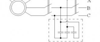
The direct start circuit looks like this (k – magnetic starter)
Rheostat start of an asynchronous drive
Before the advent of reliable and high-quality controlled semiconductor converters, the most common way to control the start of an asynchronous motor was a rheostat start. This type of launch of asynchronous drives is still popular today.
Rheostatic starting is relevant only for asynchronous motors that have a wound rotor with special terminals for connecting resistances. The main advantage of the rheostatic start of an asynchronous drive is the fact that when resistance is introduced into the rotor circuit, the motor torque does not drop, only its speed decreases.
Therefore, in drives that are forced to start under load, asynchronous motors with a wound rotor are most often used, the start-up of which is carried out not by switching from star to delta, but by removing rotor resistances.
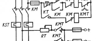
There are a lot of rheostatic starting circuits for an asynchronous drive, but they have one thing in common: active resistances are sequentially output in the rotor circuit of the engine as it accelerates. Usually they are shunted by the power contacts of individual contactors, but there are asynchronous drives, the start of which is controlled by a stepless rheostat.
For example, the rotor circuits of asynchronous motors of many mine hoisting machines contain liquid rheostats. These are devices with fixed and movable electrodes located and moving in a reservoir filled with a special electrolyte.
The use of a liquid rheostat not only allows for a smooth, stepless start, but also helps to avoid such undesirable phenomena as an electric arc when removing resistances, which is important for powerful engines.
Stepped rheostat starting circuits differ in some variety. The most popular of them are:
1. Rheostatic step start using a command controller. The operator controlling the drive switches the handle of the controller, which alternately turns on the contactors located in the rotor circuit of the motor and shunt resistors. In this case, the drive operator requires some experience and an understanding of the correct operation of the drive, since he will determine the duration of engine operation at each acceleration stage independently, “by eye.”
This starting scheme is typical for industrial mechanisms that have an uneven operating mode with frequent starts and stops under different conditions. The most typical case is a tram car or a crane.
2. Rheostatic step start as a function of time. For drives that start only under the same conditions, it is possible to calculate not only the resistance value of each stage of the rheostat in order to avoid jerks and current surges, but also to determine the required operating time at each stage. By installing a time relay in the circuit of contactor coils of the rotor circuit, you can provide the engine with an almost perfect start by pressing just one button. All that is needed is to select the correct setting for each relay.
3. Rheostatic step start as a function of current. This is a more complex scheme for starting an asynchronous motor, taking into account the starting conditions. A rectifier is installed in the rotor circuit of the engine, the voltage from which is supplied to the current relay.
When the current reaches a certain value, the drive switches to the next stage of the rheostat. Thus, starting the same drive under different conditions may take different times. But for the drive operator it will be enough to simply press the “START” button, as in the case of start in the time function.
Starting an asynchronous motor with a wound rotor starting current
Asynchronous motors can be started at full voltage (direct starting) or at reduced voltage.
Direct starting is carried out using switches, switches, magnetic starters and other starting devices.
During direct starting, the motor is supplied with full mains voltage. The disadvantage of this starting method is the large starting currents, which are 2-7 times greater than the rated currents of the motors.
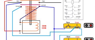
The simplest is the direct start of asynchronous motors with a squirrel-cage rotor. Starting and stopping such motors is done by turning on or off a switch (magnetic starter), etc. In Fig. 261 shows a diagram of the direct start of an asynchronous squirrel-cage motor.
Rice. 261. Direct start of an asynchronous motor with a squirrel-cage rotor
To reduce the starting currents of asynchronous motors with a squirrel-cage rotor, the voltage supplied to the motor stator windings is reduced.
Let's take a closer look at the method of starting asynchronous motors at reduced voltage using a star-delta switch.
In Fig. 262 shows a schematic diagram of switching on the stator winding with a star-delta switch. When starting, the stator winding is connected in a star using a switch and, as soon as the engine reaches the maximum possible rotation speed, the switch is tilted to the left, the stator winding is connected in a triangle. With this method of starting the engine, the starting current is reduced by three times. Let's explain this with an example.
Rice. 262. Switching the stator winding from star to triangle when starting the engine
In Fig. 263, and the stator winding is schematically shown, connected during star starting. Let the voltage between the linear wires of the motor be equal to 380 V, and therefore the voltage per phase of the motor at start-up:
Rice. 263. Turning on the motor stator winding: a - star, b - triangle
Several ways to start an asynchronous motor
- Direct start
- Undervoltage starting
- Connecting the rotor to the rheostat during switching on
- Starting a single-phase motor
- Applying resistance at start
- Using a capacitor
There are requirements that the starting of an asynchronous motor must meet. Firstly, there is no need to use special devices. Secondly, this is the reduction of starting currents to a minimum and the starting torque (hereinafter referred to as Mstart ) to a maximum. Let's consider methods of starting an asynchronous motor that meet the requirements.
Starting an asynchronous motor
Starting properties of engines .
When starting, the engine rotor, overcoming the load torque and moment of inertia, accelerates from rotation speed n = 0 to n . In this case, the slip changes from s p = 1 to s . When starting, two basic requirements must be met: the torque must exceed the moment of resistance ( Mvr>Ms ) and the starting current I p must be as small as possible.
Depending on the design of the rotor (short-circuit or phase), motor power, and the nature of the load, various starting methods are possible: direct starting, starting using additional resistances, starting at reduced voltage, etc. Below, various starting methods are discussed in more detail.
Direct start.
Starting a motor by directly connecting the stator winding to mains voltage is called direct starting. The direct start circuit is shown in Fig. 3.22. When the switch is turned on at the first moment, slip s = l , and the reduced current in the rotor and the stator current equal to it
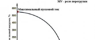
are maximum (see paragraph 3.19 at s=1). As the rotor accelerates, the slip decreases and therefore at the end of the start the current is significantly less than at the first moment. In serial motors with direct starting, the multiplicity of the starting current is kI = IP / I1NOM = ( 5,..., 7), with a larger value referring to motors of higher power.
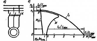
The starting torque value is found from (3.23) at s = 1:
From Fig. 3.18 it can be seen that the starting torque is close to the nominal and significantly less than the critical one. For serial engines, the starting torque multiplicity is MP/MNOM = (1.0,…,1.8).
The data shown shows that during direct starting, a current surge occurs in the network supplying the motor, which can cause such a significant voltage drop that other motors powered from this network may stop.
On the other hand, due to the small starting torque when starting under load, the engine may not overcome the moment of resistance on the shaft and will not move. Due to these disadvantages, direct starting can only be used for low and medium power motors (up to approximately 50 kW).
Starting engines with improved starting properties.
Improving the starting properties of asynchronous motors is achieved by using the effect of current displacement in the rotor due to the special design of the squirrel cage. The effect of current displacement is as follows: the flux linkage and inductive reactance X2 of the conductors in the rotor slot are higher, the closer to the bottom of the slot they are located (Fig. 3.23). Also X2 is directly proportional to the frequency of the rotor current.
Consequently, when starting the engine, when s = 1 and f2 = f1 = 50 Hz, inductive reactance X2 = max and under the influence of this, the current is forced into the outer layer of the groove. The current density j along the h coordinate is distributed along the curve shown in Fig. 3.24. As a result, the current mainly passes through the outer section of the conductor, i.e. over a significantly smaller cross-section of the rod, and, consequently, the active resistance of the rotor winding R2 is much greater than during normal operation. Due to this, the starting current decreases and the starting torque of the MP increases (see (3.37), (3.38)).
As the engine accelerates, the slip and frequency of the rotor current drops and by the end of the start reaches 1 - 4 Hz. At this frequency, the inductive reactance is small and the current is distributed evenly over the entire cross-section of the conductor. With a strongly pronounced current displacement effect, direct starting becomes possible with lower current surges and higher starting torques.
Engines with improved starting properties include engines with deep slot rotors, double squirrel cage rotors, and some others.
Motors with deep slots.
As shown in Fig. 3.25, the rotor groove is made in the form of a narrow slot, the depth of which is approximately 10 times greater than its width. The winding in the form of narrow copper strips is placed in these slot-slots. The magnetic flux distribution shows that the inductance and inductive reactance at the bottom of the conductor are significantly greater than at the top.
Therefore, when starting, the current is forced into the upper part of the rod and the active resistance increases significantly. As the engine accelerates, the slip decreases, and the current density across the cross section becomes almost the same.
In order to increase the effect of current displacement, deep grooves are made not only in the form of a slot, but also in a trapezoidal shape. In this case, the depth of the groove is slightly less than with a rectangular shape.
Double cage engines.
In such motors, the rotor windings are made in the form of two cages (Fig. 3.26): in the outer slots 1 there is a winding made of brass conductors, in the inner slots 2 there is a winding made of copper conductors.
Thus, the outer winding has a higher active resistance than the inner one. When starting, the outer winding is coupled to a very weak magnetic flux, and the inner winding is coupled to a relatively strong field. As a result, the current is forced into the outer cell, and there is almost no current in the inner cell.