There is another, more popular full-wave rectifier design based on a four-diode configuration. This design is known as a full-wave bridge rectifier or simply a bridge rectifier.
The advantage of this type of rectifier over the center-tapped version of the rectifier is that it does not require a center-tapped mains transformer in the secondary, which dramatically reduces its size and cost.
Hantek 2000 - 3 in 1 oscilloscope
Portable USB oscilloscope, 2 channels, 40 MHz….
More details
Also, this design uses the entire secondary voltage as input. Using the same transformer, we get twice the peak voltage and twice the DC voltage with a bridge rectifier than with a center-tapped full-wave rectifier. This is why bridge rectifiers are used much more often than full-wave midpoint rectifiers.
Full Wave Bridge Rectifier
To rectify both half cycles of a sine wave, as we discussed earlier, a bridge rectifier uses four diodes connected together in a “bridge” configuration. The secondary winding of the transformer is connected on one side of the diode bridge, and the load on the other.
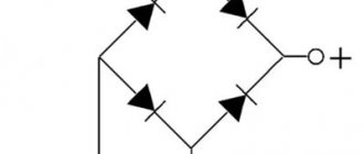
The following figure shows the circuit of a bridge rectifier.
During the positive half-cycle of the AC voltage, diodes D1 and D2 are forward biased, while diodes D3 and D4 are reverse biased. This creates a positive voltage across the load resistor (note the plus and minus polarity on the load resistor).
During the next half cycle, the polarity of the alternating voltage is reversed. Now diodes D3 and D4 are forward biased, and diodes D1 and D2 are reverse biased. This also creates a positive voltage across the load resistor as before.
Power supply 0…30 V / 3A
Adjustable power supply assembly kit…
More details
Note that regardless of the polarity of the input voltage, the polarity across the load is constant and the current in the load flows in one direction. Thus, the circuit converts the input AC voltage into a pulsating DC voltage.
If you have difficulty remembering the correct diode placement in a bridge rectifier circuit, you can refer to an alternative diagram representation. This is exactly the same circuit, except that all the diodes are horizontal and pointing in the same direction.
Bridge device type
A three-phase bridge rectification circuit uses six diodes (or thyristors if control is required). The output voltage is characterized by three values: minimum U, average U and peak voltage. A full-wave three-phase rectifier is similar to a Heitz bridge.
A conventional three-phase rectifier does not use a neutral. For 230 V / 400 V network between two rectifier inputs. Indeed, there is always a composite voltage U (= 400 V) between the 2 inputs. An uncontrolled device means that the average output U cannot be adjusted for that input U. Uncontrolled rectification uses diodes.
A controlled rectifier allows you to regulate the average output voltage by influencing the response delay of the thyristor (used instead of diodes). This command requires complex electronic circuitry. The diode behaves like a thyristor loaded without delay.
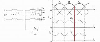
Output U three-phase output voltage. There are 7 curves in total: 6 sinusoids and a red curve connecting the upper part of the sinusoids (“sinusoidal caps”). 6 sinusoids represent 3 voltages that make up U between phases and 3 identical voltages, but with opposite sign:
U31 = -U13U23 = -U32U21 = -U12.
The red curve represents U at the output of the rectifier, that is, at the terminals of the resistive load. This U does not refer to neutral. She swims. This U fluctuates between 1.5 Vmax and 1.732 Vmax (root of 3). Umax is the peak value of one voltage and is 230 × 1.414 = 325 V. Popular models of bridge rectifiers are presented in the table below:
Table of characteristics of popular models of bridge rectifiers.
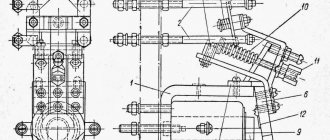
Device operation diagram
A bridge rectifier consists of four diodes connected in a "bridge" shape, with the transformer secondary winding connected through the opposite corners of the "bridge" and the load resistance connected through the other two corners. The output voltage of a bridge rectifier is twice that of a full-wave rectifier because the bridge carries all of the secondary voltage.
During the first half of the AC cycle, current flows from the negative side of the secondary winding through diode D1, through load resistance RL, through diode D3, to the positive side of the secondary winding. This current through RL is a positive half-wave.
During the second half of the AC cycle, current flows from the negative side of the secondary winding through diode D4, through load resistance RL, through diode D2, to the positive side of the secondary winding. This current through RL is a positive half-wave.
Properties of three-phase voltage
A curve acting only on a resistive load, uncontrolled rectification (with diodes), does not return to zero, unlike a monofrequency device (Graetz bridge). Thus, the ripple is much lower and the dimensions of the inductor and/or smoothing capacitor are less restrictive than for a Heitz bridge.
At least two phases are required to obtain a non-zero output U. Minimum, maximum and average voltage value. Numerically, for a 230 V / 400 V network, the rectified voltage fluctuates between a minimum voltage: 1.5 V min = 1.5 x (1.414×230) = 488 V, and a maximum: 1.732 Vmax = 1.732 x (1.414×230) = 563 IN.
It will be interesting➡ What is electromotive force (EMF) and how to calculate it
Output voltage of three-phase output rectifier (zoom). 3-phase full wave rectifier MDS 130A 400V. 5 terminals: 3 phases, + and -. This rectifier contains 6 diodes.
Thus, the following points can be summarized:
- 6 diodes, 2 diodes per phase - weak ripple compared to a single-wave rectifier (Heetz bridge);
- average value of rectified voltage: 538 V for a network of 230 V / 400 V;
- the neutral is not used by the three-phase rectifier.
DC output voltage value
Here the formula for calculating the average voltage value is the same as for a full-wave rectifier with a midpoint:
This equation tells us that the DC voltage value is about 63.6 percent of the peak value. For example, if the peak AC voltage is 10V, then the DC voltage will be 6.36V.
When you measure the voltage at the output of a bridge rectifier using a voltmeter, the reading will be equal to the average value.
Operating principle
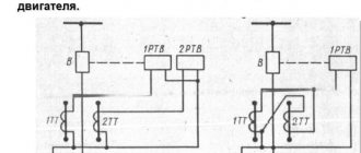
Devices for rectifying, detecting and mixing signals can be built on the basis of bridge circuits. In this circuit, the alternating voltage applied to the opposite nodes of the diode bridge is converted into a pulsating rectified voltage, which is removed from the other two nodes. When the load resistor RH is turned on, the ripple voltage generated across it is unipolar, which is typical for full-wave rectification.
When a half-wave alternating voltage of positive polarity is applied to the input, terminal T1 will be positive with respect to terminal 7Y. In this case, electrons enter terminal T2 and are output through terminal T1.
Electrons from terminal T2 arrive at the assembly with diodes D3 and D4, and only D3 has the switching direction required for conduction. Therefore, the electrons move, having passed through this diode, to the node with diodes D3. and Db. The polarity of the voltage applied to the diode Db is blocking, so that the electrons from this node go to the resistor.
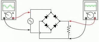
Bridge rectifier operation
When current flows through resistor RH, a voltage drop occurs across the latter (the polarity is indicated in the figure). After passing through the resistor, the electrons reach the node with diodes D2 and D4. But only on diode D2 there is a gate voltage that allows electrons to move to terminal T1, the potential of which is positive for a given half-wave of alternating current. Diode D4 turns out to be locked, since the potential T2 is negative.
Bridge Rectifier - A device or circuit that conducts current during both halves of an alternating current cycle. Since the bridge rectifier uses all the secondary voltage, the output voltage is twice that of a full-wave rectifier.
During the next half-cycle of the input voltage change, the potential of terminal T1 is negative, and terminal T2 is positive. Therefore, electrons from the TI terminal move to the node with diodes D] and D2, and since only the diode D] has the necessary switching polarity for conductivity? electrons pass through this diode and again enter the resistor RH, creating a voltage drop across it of the same polarity as in the first case. Next, the electrons, as before, arrive at the node with diodes D2 and D4, but they pass to terminal T2 through diode D4.
Interesting read! What is a varistor and where is it used?
Thus, since a bridge rectifier uses each half-cycle of the input AC voltage and reverses the phase of the negative polarity oscillation to produce a unipolar ripple voltage at the output of the circuit, it provides full-wave rectification.
A significant disadvantage of the midpoint full-wave rectification circuit is the need for two input voltage sources. This need is due to the fact that one of the terminals of the load resistance periodically switches between two voltage sources, and the other terminal is constantly connected to the midpoint of these sources.
However, the need for a midpoint will disappear if the second output of the load, using a second similar diode circuit, is connected synchronously and in antiphase to the outputs of the power supplies that are not used for the corresponding time interval.
It will be interesting➡ Electric circuit and its elements
The circuit implementation of this method is presented below. This circuit is called a single-phase bridge rectifier and is probably the most common of all rectification circuits designed to work with single-phase AC voltage sources.
Just like in a full-wave rectification circuit with a midpoint, in a bridge circuit the voltage is applied to the load during the entire period of voltage change Uin. Moreover, its value at Uin = Uin1 + Uin2 is twice the output voltage of the circuit in Fig. 3.4-8. Therefore, at the same load voltage in the bridge circuit, a voltage is applied to the reverse-biased diodes that is two times less than in the circuit in Fig. 3.4-8 (Uobrmax=Uinmax=π⋅Unsr/2.
The fundamental ripple frequency of the rectified voltage in a full-wave bridge circuit will be equal to twice the frequency of the input voltage. The ripple coefficient is the same as in a full-wave circuit with a midpoint: Kp=0.67.
Three-phase bridge rectifier
A feature of the bridge circuit is that it has two diodes connected in series with the load at all times, while in the single-phase half-wave and single-phase full-wave circuits described above there is only one such diode.
Therefore, at low input voltages (4...5 V), the use of a bridge circuit may be ineffective (the voltage drop across the diodes will be comparable in magnitude to the output voltage of the rectifier) - to increase the efficiency, a full-wave circuit with a midpoint is usually used (it is also possible to switch to using Schottky diodes with low voltage drop at forward bias).
As the voltage increases, the difference in the efficiency of the circuits decreases and the determining factor becomes the amount of reverse voltage applied to the blocked diodes during operation of the rectifier. Therefore, at high output voltage levels, a bridge rectifier is usually used.
The single-phase fully controlled rectifier allows you to convert single-phase AC to DC. It is commonly used in various applications such as battery charging, speed control of DC motors and front end UPS (Uninterruptible Power Supply) and SMPS (Switched Mode Power Supply).
All four devices used are thyristors. The moments when these devices are turned on depend on the trigger signals. Shutdown occurs when the current through the device reaches zero and is reverse biased for at least a duration equal to the device shutdown time specified on the data sheet:
- In positive semi-cyclic thyristors T1 and T2 are fired at an angle α.
- When T1 & T2 conduct Vo = Vs IO = is = Vo / R = Vs / R.
- In the negative half-cycle of the input voltage SC3, T3 and T4 are driven at an angle (π + α).
- Here the output current and supply current are in opposite directions. T3 & T4 are switched off at 2π.
If a bridge rectification circuit is used in conjunction with a source equipped with a midpoint, and the middle output of each pair of diodes is connected to the midpoint of the input source through its own load, the output of the rectifier will produce two voltages of equal but opposite sign (Fig. 3.4-10). This rectifier circuit is often used to power devices built using operational amplifiers.
DC voltage filtering
The output signal we get from a full-wave bridge rectifier is essentially a pulsating DC voltage that rises to a maximum and then drops to zero.
In order to get rid of ripples, we need to filter the two-wave signal. One way to do this is to connect a smoothing capacitor.
Initially the capacitor is discharged. During the first quarter of the cycle, diodes D1 and D2 are forward biased and because of this, the smoothing capacitor begins to charge. The charging process continues until the voltage from the bridge rectifier reaches its peak value. At this moment, the voltage across the capacitor will be equal to Vp.
After the voltage from the rectifier reaches its peak, it begins to decrease. As soon as the voltage drops below Vp the corresponding pair of diodes (D1 and D2) will not conduct.
When the diodes are turned off, the capacitor discharges through the load until the next peak is reached. When the next peak occurs, the capacitor is charged through diodes D3 and D4 to the peak value.
Three-phase device (Larionov circuit)
A three-phase bridge rectifier (Fig. 2.2, a) can be considered as a connection of two three-phase rectifiers with a zero terminal, in one of which diodes VD1, VD3, VD5 form the cathode group, and in the other diodes VD2, VD4, VD6 form the anode group. The transformers of these rectifiers are combined into one. When a bridge circuit operates, two diodes always conduct current; one in the anodic and the other in the cathodic group.
At any moment in time, the diode in the cathode group will be open whose potential, relative to the midpoint of the transformer, is higher (more positive) than the anode potential of other diodes. In the anode group, the diode conducts, the potential of which is lower (more negative) in relation to the potentials of the cathodes of other diodes.
For example, at the moment of time θ = θ1 (Fig. 2.2, b), diode VD1 conducts in the cathode group, and VD6 conducts in the anode group. The transition of current from diode to diode in both groups occurs at the natural commutation points K1, K2, K3,..., A1, A2, A3, etc. The order in which the diodes come into operation corresponds to their numbers.
It will be interesting➡ What is step voltage and why is it dangerous?
Thus, in relation to the zero point of the transformer, the potential of the common cathodes is measured along the upper envelope, and the potential of the common anodes is measured along the lower envelope of the phase voltage curves ua, ub, uc.
The instantaneous rectified voltage ud of the bridge rectifier is equal to the potential difference between the cathode and anode groups and corresponds to the ordinates contained between the upper and lower envelopes. Ripple of the rectified voltage ud and current id a, with an active load, the key K is closed, occurs with a frequency of six times relative to the network frequency.
Material on the topic: What is a control relay.
The shape of the rectified current and the current through the diode is shown in Fig. 2.2, c, d, with an active load of the rectifier rв and the rectifier operating on the excitation winding (see Fig. 2.2 c, dashed line). The reverse voltage has the same shape as in the zero circuit, but with half the amplitude. The current in each phase of the secondary winding of the transformer flows twice per period in opposite directions. In this regard, in the bridge circuit there is no forced magnetization of the transformer core.
The shape of the primary current is found from the condition of compensation of magnetomotive forces (MFF) of the primary and secondary windings when the primary winding is connected in a star. The rectifier is loaded onto the excitation winding.
The design relationships for the bridge circuit are found from general formulas (2.1 – 2.8), with m = 6. With a comparative analysis of three-phase zero and bridge circuits, the same conclusions can be drawn as for the corresponding single-phase circuits.
Improving the harmonic composition of the rectified voltage and mains current curves is achieved in multiphase rectification circuits used for high-power machines. In practice, twelve-phase rectification circuits (m = 12), formed by a series or parallel connection of two bridge rectifiers, are widely used.
Calculation of rectifiers
Disadvantages of a bridge rectifier
The only drawback of the bridge rectifier is that the output voltage is less than the input voltage by 1.4 V, as a result of the drop across the two diodes.
This drawback is only noticeable in very low voltage power supplies. For example, if the peak source voltage is only 5V, then the load voltage will only have 3.6V.
But if the peak source voltage is 100 V, the load voltage will be close to the ideal full-wave voltage and the effect of diode drop will not be significant.