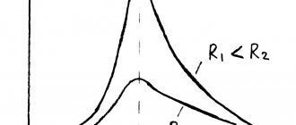
Generation and transmission of alternating electric current
Alternating current is a current whose magnitude and direction change periodically. It is thanks to alternating current that we have light and heat in our homes today. It is only thanks to alternating current that all industrial enterprises and production facilities of our time operate. Without alternating current, the technological progress of modern civilization would simply be impossible.
To produce alternating current, electromechanical devices called induction generators are used. In them, the mechanical energy obtained in one way or another is transferred to the rotor, the rotor rotates, as a result, the mechanical energy of rotation of the rotor is converted into electrical energy through electromagnetic induction.
Recall that if you rotate a magnet inside a conducting frame, an alternating current will be induced in the frame. The generator operates on this principle. Only in an industrial generator the role of the frame is played by the stator, and the role of the magnet is played by a rotor with a magnetizing winding, essentially a rotating electromagnet.
In an industrial generator, the stator is a huge ring-shaped steel structure with grooves on its inside. A copper three-phase winding is laid in these grooves. The magnetic field, as we have already said, is created by the rotor, which is a steel core with a pair (or several pairs, depending on the rated speed of rotation of the rotor) of poles generated by the current in the rotor winding. Direct current is supplied to the rotor winding from the exciter.
From the schematic diagram of a two-pole induction alternating current generator, it is easy to understand that the lines of force of the rotor magnetic field intersect the turns of the stator winding, while once per revolution the magnetic flux of the rotor changes its direction in relation to the same turns of the stator.
Thus, the stator winding produces alternating current, and not pulsating direct current. If we are talking about a nuclear power plant, then the generator rotor receives mechanical rotation from steam, which is supplied under enormous pressure to the turbine blades associated with the rotor. Steam in a nuclear power plant is produced from water, which is heated by the heat from the nuclear reaction supplied to the water through a heat exchanger.
In Russia, the frequency of alternating current in the network is 50 Hz, which means that the rotor of a two-pole generator needs to make 50 revolutions per second. So, at a nuclear power plant, the rotor makes 3000 revolutions per minute, which exactly gives the frequency of the generated current at 50 Hz. The direction of the generated current changes according to a sinusoidal (harmonic) law.
The generator winding is divided into three parts, so the alternating current is three-phase. This means that in each of the three parts of the stator winding the resulting EMF is shifted in phase relative to each other by 120 degrees. The effective value of the voltage generated at the power plant can be from 6.3 to 36.75 kV, depending on the type of generator.
To transmit electrical energy over long distances, high-voltage power lines (PTLs) are used. But if electricity is transmitted without conversion, at the same voltage that comes out of the generator, then the energy losses during transmission will be colossal, and practically nothing will reach the end user.
The fact is that energy losses in transmission wires are proportional to the square of the current and are directly proportional to the resistance of the wires (see Joule-Lenz Law). This means that for more efficient transmission and distribution of electricity, the voltage must first be increased several times so that the current decreases by the same amount and, consequently, transport losses are greatly reduced. And only increased voltage makes sense to transmit to power lines.
Therefore, electricity from the power plant is first supplied to the transformer substation. Here the voltage increases to 110-750 kV and only after that it is supplied to the power line wires. But the consumer needs 220 or 380 volts, so at the end of the line the high voltage is lowered back, again using transformer substations, to 6-35 kV.
A transformer is installed at a substation near our house or built into the house. Here the voltage drops again - from 6-35 kV to 220 (380) volts, which are already distributed to consumers. A network of wires and cables disperses through the input distribution device into different rooms.
Obtaining alternating sinusoidal current
Method for producing alternating current
The advantage of alternating current over direct current is:
- It is quite easy to move over long distances with minimal losses.
- The voltage value can be changed using a transformer.
- AC motors are simple to operate, easy to design and light in weight.
If a copper wire frame is placed in an electromagnetic field and begins to rotate, a potential difference will appear at its ends. And if the frame is closed through the load, then an electrical alternating sinusoidal current will flow. The magnitude and polarity of the alternating current will depend on the position of the frame in the electromagnetic field, and with its uniform rotation we obtain an alternating sinusoidal current.
Frame rotation in an electromagnetic field
Depending on the frame rotation speed, we obtain different alternating current frequencies. To increase the EMF value, the number of turns is added, and a multi-turn coil is obtained. Synchronous generators are used to generate alternating current. The synchronous alternating current generator can withstand large current overloads well and easily stabilizes the alternating current frequency and emf.
Power plants operate on three-phase generators that produce three-phase voltage. This voltage is considered economically beneficial and, from a technical point of view, a good solution for operating electric generators. For generators whose rotor has a rotation speed of 3000 rpm with a frequency of 50 Hz, only two poles are needed, and at 1500 rpm the generator has four poles.
A synchronous generator contains a stator with windings, a rotor with an excitation coil and brushes. The brushes slide along the rings and therefore the electromagnetic field does not change sign and direction. It is possible to change the magnitude of the excitation current and automatically maintain the operating mode of the synchronous generator. New Omsk prostitutes, independents, call girls.
Generator device
In industrial quantities, electricity is generated by three-phase synchronous generators. In particular cases, single-phase and three-phase generators are used. For power tools with high starting currents, synchronous generators are used, which can withstand large short-term current overloads well. For private homes where there are no large overloads, asynchronous generators are used.
The coils of a three-phase generator can have two types of connections, as for a three-phase load - these are star and delta connections. In generators, electric current is produced in three windings connected in a star configuration. This type of connection is more economical, since it does not have a fourth wire.
From the common connection point of the windings, with the same voltages and loads on 3 phases, the wire is not removed. So in symmetrical networks with equal loads, a common wire is not necessary. In low-voltage electrical networks, for single-phase loads, a uniform load is not possible, so four-wire networks with a solidly grounded neutral are used here.
The voltage between phases is called line voltage, and between a phase and the central wire is called phase voltage. In power plants and substations, a star connection scheme is used. For low-voltage networks up to 1000 V, the line voltage (between phases) is 380 V, and the voltage between phase and neutral (phase) is 220 V.
Networks up to 1000 V using different loads in different phases may have phase imbalance. According to the rules of the PUE, networks up to 1000 V must be four-wire with a solidly grounded neutral. Thus, at the step-down substation, the neutral wire from the secondary winding of the transformer is connected to the grounding device and the fourth wire goes to consumers.
Four-wire secondary winding of the substation
It is not always rational to use synchronous generators. Sometimes it becomes necessary to obtain alternating voltage from constant 12-220 V or 24-220 V. In this case, electronic converters are used. In cheap versions of electronic converters, the AC sine wave is impure. Therefore, they are suitable for active loads (incandescent lamps, heating elements, various heaters). For inductive loads (electric motors) you need a pure sine wave of alternating voltage. Such electronic converters are much more expensive.
Alternating electric current
Alternating current - or AC ( Alternating Current ). Designation (
Electric current is called alternating if it changes its direction over time and continuously changes in magnitude.
Alternating current , which is used to connect household or industrial electrical appliances, varies according to a sinusoidal law:
i = Imsin(2πft)
AC graph
- i – instantaneous current value
- Im – amplitude or maximum current value
- f – AC frequency value
- t – time
Alternating current is widely used due to the fact that alternating current electricity can be technically simply and economically converted from lower voltage energy to higher voltage energy and vice versa. This property of alternating current allows electricity to be transmitted through wires over long distances.
AC period
Industrial alternating electric current is obtained using electric generators, the operating principle of which is based on the law of electromagnetic induction. The generator is rotated by a mechanical engine using thermal, hydraulic or nuclear energy.
Alternating single-phase electric current has the following main characteristics:
f – frequency of alternating current determines the number of cycles or periods per unit of time. The unit of measurement for alternating current frequency is Hertz (Hz):
1Hz = 10 3 kHz = 10 6 MHz
Τ – period – time of one complete change of a variable.
If 1 period T occurs in 1 second, then the frequency f = 1 Hz (Hertz).
1s = 10 3 ms = 10 6 µs = 10 12 ns
In the Russian Federation, the period Τ of alternating current is taken equal to 0.02 seconds, therefore, using the formula f = 1/T, the frequency of alternating current can be determined:
ω – angular velocity
In addition to the frequency f, when studying AC circuits, the concept of angular velocity ω is introduced. Angular velocity ω is related to frequency f by the following relationship:
At a frequency of 50 Hz, the angular velocity is 314 rad/s (2 × 3.14 × 50 = 314).
Instantaneous value ( i,u,e,p ) – the value of a quantity at a given moment, instantaneous.
Maximum or amplitude value ( Im,Um,Em,Pm ).
The effective value of the current is the value of the alternating current, equal to the current that, at the resistance R, creates heat generation equal to this alternating current, for the same time t ( I,U,E,P).
Getting a sine curve
In the system of Cartesian rectangular coordinates, a trigonometric circle and a curve are combined, reflecting the change in the value of the trigonometric function sinβ from the angle β between the 0x axis and the radius vector r. The radius vector r rotates counterclockwise. Let's rotate the radius vector by an angle β and from the end of the vector r draw a dotted line parallel to the 0x axis. From the circle (point a) along the 0x axis we plot a segment to scale. From the end of the segment we construct a perpendicular to the intersection with the dotted line. We obtain point c at the intersection of the perpendicular and the dotted line.
AC sine wave
We will carry out a similar construction, increasing the angle β until the radius vector rotates through the angle β = 360°, and we will obtain points similar to point c. Let's connect the points of a smooth curve, which will reflect the sinusoidal law of change in the magnitude of alternating current.
Concept of phase
If two variables simultaneously pass through their zero and maximum values, then they are in phase.
If two variables do not simultaneously pass through their zero and maximum values, then they are out of phase.
EMF in the generator winding
With uniform rotation of the rotor in its winding (in Fig. 12.2, a - in a coil), e.m. is induced. d.s., determined by the formula
Substituting the expression for magnetic induction, we get
At β = 90°, i.e., in the position of the conductor under the middle of the pole, the greatest emf is induced.
The EMF equation can be written as follows:
Given the formula
, we obtain the same dependence of emf. from time, as when rotating the frame (see Fig. 12.1), considering the initial position of the turn (t=0), when its plane coincides with the neutral:
Thus, in this case as well. d.s. is a sinusoidal function of time (Fig. 12.5). The same result is obtained if the poles are rotated and the conductors are left motionless.
In a rectangular coordinate system, e. d.s. can be represented as a function of angle β=ωt or as a function of time t. The dependence e(ωt) and e(t) can be represented by one curve, but at different scales along the abscissa axis, differing by ω times.
Receiving alternating electric current
Alternating current, in the traditional sense, is the current obtained due to alternating, harmonically varying (sinusoidal) voltage. Alternating voltage is generated at the power plant, and is constantly present in any wall outlet.
To transmit electricity over long distances, alternating current is also used, since alternating voltage is easily increased using a transformer, and thus electrical energy can be transmitted over a distance with minimal losses, and then lowered back using a transformer to a value acceptable for a household network.
The generation of alternating voltage (and therefore current) is carried out at a power plant, where industrial alternating current generators are driven by turbines driven by high pressure steam. Steam is produced from water that is highly heated by the heat generated by a nuclear reaction or by burning fossil fuels, depending on the type of power plant. In any case, the rotation of the alternator is what causes alternating voltage and current to be generated.
To answer the question of how alternating current is generated in a generator, it is enough to consider an elementary model consisting of a piece of wire and a magnet, simultaneously recalling the Lorentz force and the law of electromagnetic induction. Let's say a wire 10 cm long lies on the table, and we have in our hand a strong neodymium magnet, the size of which is slightly smaller than the wire. Let's connect a sensitive galvanometer or pointer voltmeter to the ends of the wire.
Let's bring the magnet with one of the poles close to the wire, at a distance of less than 1 cm, and quickly move the magnet over the wire across it from left to right - we will cross the conductor with the magnetic field of the magnet. The galvanometer needle will sharply deviate in a certain direction, then return to its original position.
Let's turn the magnet over with the other pole facing the wire. And again, by moving your hand from left to right, we quickly cross the experimental conductor with a magnetic field. The galvanometer needle deviated sharply in the other direction, then returned to its original position. Instead of turning the magnet over, you can first move from left to right, and then from right to left, the effect of changing the direction of the generated current will be similar.
The experiment showed that to obtain an alternating voltage, we need to either move the magnet across the wire to the right and left, or cross the conductor with alternating magnetic poles. The power plant generator (and all traditional alternators) uses the second option.
The operating principle of the generator is to produce variable electromotive force (voltage)
AC sinusoidal voltage
An alternating current generator in a power plant consists of a rotor and a stator. The mechanical energy of the rotating turbine is transferred to the rotor. The rotor's magnetic field is concentrated at its pole pieces, and is created either by permanent magnets attached to it, or by direct voltage current flowing in the copper winding of the rotor.
Typically, the stator winding consists of three separate windings offset relative to each other in space, resulting in an alternating voltage and current in each of the three windings. Thus, each of the three stator windings is a source of alternating voltage, and the instantaneous voltage values are shifted in phase relative to each other by 120 degrees. This is called three-phase alternating current.
Obtaining three-phase alternating voltage and current
The generator rotor with two magnetic poles, rotating at a frequency of 3000 revolutions per minute, produces 50 crossings of each phase of the stator winding per second. And since there is a zero point between the magnetic poles, that is, a place where the magnetic field induction is zero, then during each full revolution of the rotor, the voltage induced in the winding passes through zero, then changes polarity. As a result, the output voltage has a sinusoidal shape and a frequency of 50 Hz.
When an AC voltage source is connected to a load, alternating current is produced in the circuit. The voltage and maximum permissible stator current are greater, the stronger the rotor magnetic field, i.e. the greater the current flowing in the rotor windings. In synchronous generators with external excitation, the voltage and current in the rotor windings is created by a thyristor excitation system or exciter - a small generator on the shaft of the main generator.
Methods for producing alternating current
Let's say we have a frame made of conductive material. Let's place it in a magnetic field. According to the formula mentioned above, if you start to rotate the frame, an electric current will flow through it. With uniform rotation at the ends of this frame, an alternating sinusoidal current will be obtained.
This is due to the fact that, depending on the position along the rotation axis, the frame is penetrated by a different number of lines of force. Accordingly, the magnitude of the EMF is not induced uniformly, but according to the position of the frame, as is the sign of this magnitude. What do you see in the graphic above. When the frame rotates in a magnetic field, both the frequency of the alternating current and the magnitude of the emf at the terminals of the frame depend on the rotation speed. To achieve a certain EMF value at a fixed frequency, more turns are made. Thus, it turns out not a frame, but a coil.
You can obtain alternating current on an industrial scale in the same way as described above. In practice, power plants with alternating current generators have found widespread use. In this case, synchronous generators are used. Because in this way it is easier to control both the frequency and the magnitude of the alternating current emf, and they can withstand short-term current overloads many times over.
Depending on the number of phases, three-phase generators are used in power plants. This is a compromise solution related to the economic feasibility and technical requirement of creating a rotating magnetic field for the operation of electric motors, which make up the lion's share of all electrical equipment in industry.
Depending on the type of force that drives the rotor, the number of poles may vary. If the rotor rotates at a speed of 3000 rpm, then to obtain alternating current with an industrial frequency of 50 Hz you need a generator with 2 poles, for 1500 rpm - with 4 poles, and so on. In the pictures below you see the device of a synchronous type generator.
There are coils or an excitation winding on the rotor; current is supplied to it from an exciter generator (Direct Current Generator - DCG) or from a semiconductor exciter through a brush apparatus. The brushes are located on rings, unlike commutator machines, as a result of which the magnetic field of the excitation windings does not change in direction and sign, but changes in magnitude when the exciter current is regulated. In this way, optimal conditions are automatically selected to support the operating mode of the alternator.
So, it was possible to obtain alternating current on an industrial scale using a method based on the phenomena of electromagnetic induction, namely with the help of three-phase generators. In everyday life, both single-phase and three-phase generators are used. The latter are recommended to be purchased for construction work. The fact is that a large number of electrical tools and machines can operate on three phases. These are electric motors of various concrete mixers, circular saws, and powerful welding machines are also powered by a three-phase network. Moreover, synchronous generators are suitable for such tasks; asynchronous ones are not suitable - due to their poor performance with devices that have high starting currents. Asynchronous household power plants are more suitable for backup power supply to private houses and cottages.
Alternating electric current
Alternating electric current
(AC, abbreviation for alternating current) is an electric current that changes in magnitude and direction with a certain periodicity. In electrical engineering, it is customary to use the tilde sign (
Sources of alternating electric current are alternating current generators, which create alternating electromotive force, the change in magnitude and direction of which occurs at certain intervals.
Basic parameters of alternating current
. The following parameters are used to describe it (see graph):
— Period (T)
— the length of time during which the electric current makes one full cycle of changes, returning to its initial value;
— Frequency (f)
- a parameter that determines the number of complete oscillations of the electric current in one second, the unit of measurement is 1 Hertz (Hz). So, for example The current frequency standard adopted in domestic power systems is 50 Hz or 50 oscillations per second.
— Current amplitude (Im)
- the maximum achieved instantaneous value of the current per period, as can be seen from the presented graph - the height of the sinusoid;
— Phase
— state of alternating sinusoidal electric current: instantaneous value, change of direction, increase (decrease) in the circuit. Alternating current can be either single-phase or multiphase.
The most widespread are three-phase systems, which are three separate electrical circuits. circuits with the same frequency and EMF, with a shift angle φ=120°. You can learn more about the concept in the article The principle of creating a three-phase alternating current circuit.
AC Application
. Alternating sinusoidal electric current is used in almost all sectors of the economy. The widespread use of alternating current is largely due to the economic efficiency of its use in power supply systems, ease of conversion from low voltage energy to higher voltage energy and vice versa.
This feature allows you to reduce the loss of electricity when transmitting it over long distances through wires, significantly reducing their cross-sectional area.
Tweet
Receiving single-phase alternating current. As is known, direct current represents the steady translational motion of free electrons. Alternating current can be thought of as the oscillatory movement of electrons. Alternating current is an electric current whose changes in magnitude and direction are repeated at regular intervals. The formation of alternating current can be illustrated with the following example.
Rice. 1
In the magnetic field formed between the north and south poles of the electromagnet, under the influence of an external force, the conductor rotates in a circle (Fig. 1). The intersection of a conductor with magnetic lines of force causes the appearance of an electromotive force in it.
Moving in a magnetic field, the conductor occupies different positions in which the angle of intersection of the conductor with magnetic lines of force changes. In positions 1 and 3, the directions of movement of the conductor and the action of the power lines coincide. In this case, the magnitude of the electromotive force will be zero; the conductor does not cross magnetic lines of force. It will reach its greatest value if the direction of the magnetic lines of force makes a right angle with the direction of movement of the conductor, i.e. in positions 2 and 4 . In intermediate positions, the emf will be equal to some values intermediate between zero and the maximum value.
Change e. d.s. and alternating current can be depicted as follows. In position 1 , when the direction of movement of the conductor coincides with the direction of the magnetic field lines, the current value is zero. As the conductor moves to point 2 , the current reaches its maximum value, after which it gradually decreases to point 3 and reaches zero 3 When the conductor moves from point 3 to point 1 , the picture repeats. However, using the right-hand rule, we will establish that the current has a direction opposite to that which it had when the conductor moved from point 1 to point 3 .
If the magnitude of the current when the conductor moves from point 1 to point 3 is denoted by segments corresponding to the current values at various points and located above the horizontal line, and the corresponding current values when the conductor moves from point 3 to point 1 - by segments below the horizontal line (since the direction of the current changes) and connect the vertices of the segments with a smooth line, we get a sinusoid (Fig. 2). E.m.f. and current varying according to a sinusoid are called sinusoidal.
Rice. 2
Period and frequency of current. When the alternating current changes along a sinusoid, its value increases from zero to the maximum value, after which it again decreases to zero; then changes direction and goes through the same stages. The time during which the current completes a full cycle of changes in magnitude and direction is called a period and is measured in seconds. The number of cycles per second is called the frequency of alternating current, which is measured in hertz ( Hz ).
All power plants in Russia and most European countries generate alternating current with a frequency of 50 Hz , in the USA - with a frequency of 60 Hz . To power electric railways in Russia they use direct current, and in many foreign countries they use alternating current of various frequencies. In radio engineering, alternating currents of the highest frequency are used - up to several billion hertz; in telephone technology, current with a frequency of about hundreds of thousands of hertz is used.
Phase shift. If not one, but two conductors shifted between each other are placed between the poles of a magnet, when these conductors rotate, an emf will be induced in them. with the same amplitudes and frequencies. The angles at which the conductors are located relative to the neutral line are called initial phase angles, or initial phases. The difference in the initial phases of sinusoidal quantities with the same frequency is called the phase shift angle, or simply the phase shift. When two sinusoids simultaneously reach zero and positive (or negative) amplitude values, they coincide in phase.
AC circuit with active resistance. In an alternating current circuit, the conductor resistance increases compared to a direct current circuit. This is due to the fact that the current density at the surface of the conductor is greater than in the middle. The resistance of AC conductors is called active. Active resistances include electric incandescent lamps, electric heating devices, and straight conductors of short length. The unit of measurement of resistance in alternating current circuits, as well as direct current, is ohm .
In an AC electrical circuit that has only active resistance, the voltage at the ends of the resistance and the current flowing through the circuit are in phase.
AC circuit with inductance. When electric current flows through a conductor, a magnetic field appears around it. Any change in current in an electrical circuit (turning on, turning off, etc.) causes the appearance of emf in the circuit. self-induction due to the intersection of a conductor with its own magnetic field. Consequently, the voltage of the current source and the emf, which arises as a result of self-induction, act in the circuit.
However, the e.m.f. self-induction is directed in such a way that it always prevents a change in current. As the current in the circuit increases, it is directed against the emf. voltage source. Consequently, the current in the circuit cannot be established immediately. If the current in the circuit decreases, an emf occurs. self-induction of such a direction that, preventing the current from disappearing, it maintains the decreasing current.
An electrical circuit in which emf occurs. With. self-induction, resists the passage of electric current. The resistance resulting from the action of the emf. self-induction is called inductive. Its unit of measurement is ohm. Considering that e. d.s. self-induction in alternating current circuits continuously counteracts changes in current; for it to flow, the network voltage must balance the emf. self-induction, i.e. the voltage in the network at every moment must be equal and opposite to the direction of e. d.s. self-induction.
The voltage applied to the circuit terminals leads the current in phase by 90° , and the current, in turn, leads the emf. self-induction also at an angle of 90° .
AC electrical circuit with active and inductive resistance. In practice, there is no separate inductive reactance: every winding, in addition to inductance, also has active resistance. The sum of inductive and active resistance connected in series is called total resistance.
AC electrical circuit with capacitor. When a capacitor is connected to a DC electrical circuit, it will be charged by the current flowing through it. After the capacitor is charged, the short-term current in the circuit will stop: for direct current, the capacitor represents an infinitely large resistance.
When the capacitor is disconnected from the current source, it remains charged. By connecting the capacitor plate with a conductor, the capacitor can be discharged, and a current will flow in the circuit, the direction of which is opposite to the direction of the charging current.
When a capacitor is connected to an alternating current circuit, the capacitor will alternately charge in one direction or the other. Alternating current will flow through the circuit. In the first quarter of the period, the target with the capacitor takes energy from the network, which is stored in the electric field of the capacitor. In the next quarter of the period, the capacitor is discharged to the network, giving it previously stored energy. Consequently, in terms of capacitance, only energy is exchanged between the network and the capacitor without any loss.
The capacitance and inductance of an electrical circuit exhibit opposite properties in an alternating current circuit, mutually compensating each other to one degree or another.
An electrical circuit with a series connection of active resistance, inductance and capacitor. The active, inductive and capacitor resistance is called the total or apparent resistance of the circuit. The phenomenon in which the emf. self-induction is completely compensated by the potential difference arising on the capacitor plates, called voltage resonance. Voltage resonance is characterized by the exchange of energy between the magnetic field of the inductive coil and the electric field of the capacitor. With voltage resonance, the partial voltages on the capacitor and inductive reactance can significantly exceed the voltage applied to the circuit, and the current with low active resistance can reach a large value. In high current technology, voltage resonance can cause a disruption in the normal operation of an electrical circuit.
An electrical circuit with a parallel connection of active resistance, inductance and capacitor. When inductance and capacitance are connected in parallel, current resonance occurs. Current resonance is a phenomenon in which the phase shift between current and voltage is reduced to zero.
When currents resonate, an energy oscillation is observed between the magnetic field of the inductive coil and the electric field of the capacitor. In a capacitor, energy is stored when the applied voltage increases and is returned back when it decreases. The coil consumes energy to create a magnetic field, and when the current decreases and the magnetic field disappears, it returns it back.
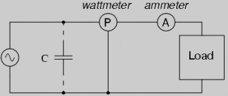
AC power. The power consumed at any moment by an electrical circuit containing active resistance and inductance is called instantaneous. It consists of the power consumed in the active resistance and the power consumed by the inductance when the current increases and returned back to the circuit when the current decreases. In electrical calculations, active power is mainly used, which represents the product of the effective values of current and voltage by “cosine phi” ( cos φ ). Active power is measured, as in DC circuits, in watts or kilowatts.
Active power is spent to perform useful work and is measured with a wattmeter. In addition to active power, in alternating current circuits there is reactive power, which is spent when the current increases to create magnetic fields in the inductive part of the circuit. As the current decreases, the circuit becomes a kind of generator, i.e., the energy stored in it returns to the generator that powers the circuit. This redistribution of energy from the generator to the circuit and back needlessly loads the line and winding of the generator, creating unnecessary energy losses.
Reactive power is measured in watt-amperes reactive ( var ) or kilovolt-amperes reactive ( kvar ).
Along with the indicated powers, there is also total or apparent power, which is the product of the effective values of voltage and current.
Power factor - “cosine phi” ( cos φ ) in an alternating current circuit is the ratio of active power to total power. The power factor for sinusoidal alternating current is the cosine of the phase shift between current and voltage. When there is only active load in the circuit, i.e. all the power is active, the power factor reaches its maximum value and is equal to unity.
Reactive power is consumed by the load, but if special measures are not taken, it will load the electrical line connecting the load to energy sources to the detriment of active power. Therefore, measures are always taken to relieve the energy source from reactive power. Only the minimum required amount of reactive power should flow through the line to the consumer.
“Cosine phi” is measured by a special device called a phase meter.
In the practice of operating electrical networks, it is necessary to strive to obtain a larger “cosine phi”; The lower cos φ the consumer has, the less active power the generator will produce, the less active power it will be loaded on and the lower the efficiency of the machine will be. Low “cosine phi” leads to the need to increase the total power of electrical stations and transformers, reduce the efficiency of transformers and generators, increase power and voltage losses in wires and increase the cross-section of wires.
In this regard, it is necessary to take into account not only the active energy taken by the consumer from the power plant, but also reactive energy. Therefore, a consumer with a reactive load is required to install electric meters for active and reactive loads.
A low “cosine phi” can be obtained due to underloading of AC electric motors, incorrect selection of the type of electric motor, or increased voltage in the network.
The “cosine phi” can be increased through the correct choice of the type, power and speed of newly installed motors, increasing the load on the motors, preventing the motors from running idle for a long time, high-quality repair of electric motors, and the use of fixed capacitors.
The light weight of capacitors, the absence of rotating parts, insignificant losses in them, safety and reliability in operation, and simple maintenance have made them widely used to increase the “cosine phi”. The capacitor should be selected in such a way that its capacitive reactance is close in value to its inductive reactance. A capacitor is connected in parallel to an inductive load.
Share the article with your friends! Let others know about us too!
RќСЂР°РІРёС‚СЃСЏ
Electricity
Modern life is unthinkable without radio and television, telephone and Internet, all kinds of lighting and heating devices, machines and devices based on the use of electric current.
Dielectrics and conductors.
Direct and alternating electric current.
Electric current is the directed movement of electrically charged particles. Depending on the interaction of electric current with certain substances, these substances are divided into conductors, dielectrics and semiconductors. Conductors are materials that conduct electric current well, while dielectrics are substances that do not conduct current. Semiconductors occupy an intermediate position between conductors and dielectrics in terms of their resistance to the passage of electric current.
For the emergence and existence of an electric current, the presence of free charged particles and a force causing their ordered movement is necessary. Typically the source of this force is electrical voltage at the ends of an electrical circuit. If the voltage does not change over time, then direct current flows in the circuit; if it changes, alternating current flows.
Alternating current
Electric current, the magnitude and direction of which changes at regular intervals of time, is called variable . Such a current is conventionally designated by the sign
Alternating current, in contrast to direct current, which always has one direction and does not change its value, changes according to a sinusoidal law
Receiving single-phase alternating current. This current is obtained from alternating current generators. The circuit of the simplest alternating current generator is shown in the figure below:
Between the N and S poles of the electromagnet, a steel cylinder A rotates, on which a frame made of insulated copper wire is mounted. The ends of the frame are attached to copper rings insulated from the shaft. Fixed brushes Ш are pressed against the rings, which are connected by wires to an energy receiver R. Rotating, the frame intersects the magnetic field lines, and electromotive forces are induced in each of its sides, which, when summed up, form a total electromotive force. With each revolution of the frame, the direction of the total electromotive force is reversed, since each of the working sides of the frame passes under different poles of the electromagnet in one revolution. The electromotive force induced in the frame also changes, as the speed at which the sides of the frame intersect the magnetic field lines changes. Consequently, with uniform rotation of the frame, an electromotive force will be induced in it, periodically changing in magnitude and direction.
If the stationary brushes Ш, connected by wires to the energy receiver R, form a closed electrical circuit, then an alternating single-phase current will flow from the energy source to the receiver.
The time during which alternating current completes a full cycle of changes in magnitude and direction is called a period. It is designated by the letter T and is measured in seconds. The number of cycles per second is called AC frequency It is denoted by the letter f and measured in hertz.
Since frequency shows the number of complete cycles of current change in magnitude and direction in one second, the period is defined as the quotient of one second divided by frequency:
In technology, alternating currents of various frequencies are used. In Russia, all power plants generate alternating current electricity at a standard frequency of 50 Hz. This current is called industrial frequency current and is used to supply electricity to industrial enterprises and for lighting.
Receiving three-phase alternating current . Three-phase alternating current is widely used in technology. Three-phase current is a system consisting of three single-phase currents of the same frequency, shifted in phase by one third of the period relative to each other and flowing through three wires. Three-phase current is obtained in a three-phase generator, which creates three electromotive forces shifted in phase by an angle of 120° (one third of a period).
The simplest three-phase current generator is a ring-shaped steel core on which three windings are located: ω1, ω2 and ω3, shifted one relative to the other along the circumference of the core by 120°. The core with windings is called stator , and the electromagnet rotating inside the stator is called the rotor . A direct current passes through the rotor winding, called the field winding, which magnetizes the rotor, forming the north N and south S poles. When the rotor rotates, the magnetic field it creates crosses the stator windings, in which an electromotive force is induced. The magnitude of the electromotive force depends on the speed at which the rotor's magnetic field lines cross the stator's magnetic field. The poles of the rotor and stator windings must be such that a sinusoidal electromotive force appears in each of the stator windings, shifted in phase by 120°.
If a load is connected to each of the three generator windings, the result will be three single-phase alternating current circuits. If the consumer resistances are equal, the amplitudes of the currents in each circuit will be equal to each other, and the phase relationships between the currents will be the same as between the electromotive forces in the generator windings. Each of the generator windings, together with the external circuit connected to it, is usually called a phase. In order to form a single three-phase system from these independent single-phase systems, it is necessary to connect the individual windings. The generator windings can be connected in two ways: star and delta.
When connecting the windings of the generator and consumers in a star (Fig. 58), four wires are used instead of the six required in an unconnected system. Reducing the number of wires increases the efficiency of the power transmission line device. The three wires running from the generator windings to the receivers /, //, III are called linear, since they constitute a line for transmitting energy from the generator to the receivers, and the wire connecting the common points of the generator and consumer phases is zero. If the loads of all three phases are equal in magnitude, then the total current in the neutral wire will be equal to zero. However, a uniform load can only be ensured by supplying three-phase consumers that are connected and disconnected by all three phases simultaneously. Single-phase consumers are switched on independently of one another, and when powering them, complete uniformity of the phase load cannot be achieved. In this case, the neutral wire must maintain equality between the different consumer voltages
The voltage between linear wires is called linear, and the voltage between each phase is called phase. When connected by a star, the linear current is equal to the phase current, and the phase voltage is 1.73 times less than the linear one with the same phase load.
Single-phase receivers, such as incandescent lamps, can be connected directly to line wires at line voltage (Fig. 59). Such a connection is called a triangle connection. This connection is used for lighting and power loads. The phases of a three-phase generator are connected as follows: the end of the first phase with the beginning of the second, the end of the second with the beginning of the third, and the end of the third with the beginning of the first, and linear wires are connected to the phase connection points. Since the phases of the consumer or generator with such a connection are connected directly to the linear wires, their phase voltages are equal to linear ones, i.e. Uph = Ul, and linear currents in absolute value are 1.73 times greater than phase currents with the same phase load. Delta connections of generator windings are quite rare. In three-phase motors, the ends of the windings can be connected in a star or triangle.
AC power. The main quantity in electrical calculations is the average, or active, power. It is calculated using the formula:
φ-phase angle between current and voltage.
With a uniform load on a three-phase system, the power consumed by each phase is the same, so the power of all three phases
The active power of three-phase alternating current when connected by star and delta is determined by the formula
The concept of cos φ and measures of its increase. In addition to active power, there is reactive power in an electrical circuit. Active and reactive powers make up the total power S. Active power P is consumed in the circuit when heat is released or useful work is performed, and reactive power Pp is consumed when the current increases to create magnetic fields in the inductive part of the circuit. When the current decreases, the circuit becomes like a generator and the energy stored in it is transferred to the generator that powers this circuit. This movement of energy from the generator to the circuit and back loads the line and winding of the generator, causing unnecessary energy losses in them. The ratio of active power to apparent power is called power factor. It shows how much of the total power is actually consumed by the circuit and is calculated using the formula
Thus, the power factor for sinusoidal alternating current is the cosine of the phase angle between current and voltage.
The increase in cos φ depends on the type, power and speed of newly installed engines, increasing their load, etc.
The concept of the thermal effect of current. When current passes through a conductor, the latter heats up. Russian academician E. H. Lenz and English physicist D. P. Joule simultaneously and independently of one another established that when an electric current passes through a conductor, the amount of heat released by the conductor is directly proportional to the square of the current, the resistance of the conductor and the time during which the current flowed through the conductor. This position is called the Joule-Lenz law and is determined by the formula:
where Q is the amount of heat, cal;
I is the current flowing through the conductor, a;
R—conductor resistance, ohm;
To protect electrical devices from excessive heating, fuses are included in the electrical circuit, and to protect electric motors during current overloads, a thermal maximum relay is used.
Electricity.
Electricity
— directed (ordered) movement of charged particles. Such particles can be: in metals - electrons, in electrolytes - ions (cations and anions), in gases - ions and electrons, in a vacuum under certain conditions - electrons, in semiconductors - electrons and holes (electron-hole conductivity). Sometimes electric current is also called displacement current, which arises as a result of a change in the electric field over time.
Electric current has the following manifestations:
- heating of conductors (no heat is released in superconductors);
- change in the chemical composition of conductors (observed mainly in electrolytes);
- creation of a magnetic field (manifests itself in all conductors without exception).
Classification:
If charged particles move inside macroscopic bodies relative to a particular medium, then such a current is called conduction electric current. If macroscopic charged bodies (for example, charged raindrops) are moving, then this current is called convection current.
There are variable
(eng. alternating current, AC),
constant
(eng. direct current, DC) and
pulsating
electric currents, as well as their various combinations. In such concepts the word “electric” is often omitted.
D.C
- a current whose direction and magnitude vary slightly over time.
Alternating current
- a current whose magnitude and direction change over time. In a broad sense, alternating current refers to any current that is not direct. Among alternating currents, the main one is the current whose value varies according to a sinusoidal law. In this case, the potential of each end of the conductor changes in relation to the potential of the other end of the conductor alternately from positive to negative and vice versa, passing through all intermediate potentials (including zero potential). As a result, a current arises that continuously changes direction: when moving in one direction, it increases, reaching a maximum, called the amplitude value, then decreases, at some point becomes equal to zero, then increases again, but in a different direction and also reaches the maximum value , decreases and then passes through zero again, after which the cycle of all changes resumes.
Quasi-stationary current
- “a relatively slowly varying alternating current, for instantaneous values of which the laws of direct currents are satisfied with sufficient accuracy” (TSC). These laws are Ohm's law, Kirchhoff's rules and others. Quasi-stationary current, like direct current, has the same current strength in all sections of an unbranched circuit. When calculating quasi-stationary current circuits due to the emerging e. d.s. inductions of capacitance and inductance are taken into account as lumped parameters. Ordinary industrial currents are quasi-stationary, except for currents in long-distance transmission lines, in which the condition of quasi-stationary along the line is not satisfied.
High frequency alternating current
- a current in which the quasi-stationary condition is no longer satisfied; the current passes along the surface of the conductor, flowing around it from all sides. This effect is called the skin effect.
Pulsating current
- a current in which only the magnitude changes, but the direction remains constant.
Eddy currents (Foucault currents)
- “closed electric currents in a massive conductor that arise when the magnetic flux penetrating it changes,” therefore eddy currents are induced currents. The faster the magnetic flux changes, the stronger the eddy currents. Eddy currents do not flow along specific paths in wires, but when they close in the conductor, they form vortex-like circuits.
The existence of eddy currents leads to the skin effect, that is, to the fact that alternating electric current and magnetic flux propagate mainly in the surface layer of the conductor. Heating of conductors by eddy currents leads to energy losses, especially in the cores of AC coils. To reduce energy losses due to eddy currents, they use the division of alternating current magnetic circuits into separate plates, isolated from each other and located perpendicular to the direction of the eddy currents, which limits the possible contours of their paths and greatly reduces the magnitude of these currents. At very high frequencies, instead of ferromagnets, magnetodielectrics are used for magnetic circuits, in which, due to the very high resistance, eddy currents practically do not arise.
Characteristics:
Historically, it was accepted that the direction of the current coincides with the direction of movement of positive charges in the conductor. Moreover, if the only current carriers are negatively charged particles (for example, electrons in a metal), then the direction of the current is opposite to the direction of movement of the charged particles.
The speed of directional movement of particles in conductors depends on the material of the conductor, the mass and charge of the particles, the surrounding temperature, the applied potential difference and is much less than the speed of light. In 1 second, electrons in a conductor move due to ordered motion by less than 0.1 mm. Despite this, the speed of propagation of the electric current itself is equal to the speed of light (the speed of propagation of the electromagnetic wave front). That is, the place where the electrons change the speed of their movement after a change in voltage moves with the speed of propagation of electromagnetic oscillations.
Main types of conductors:
Unlike dielectrics, conductors contain free carriers of uncompensated charges, which, under the influence of a force, usually an electrical potential difference, move and create an electric current. The current-voltage characteristic (the dependence of current on voltage) is the most important characteristic of a conductor. For metal conductors and electrolytes, it has the simplest form: the current strength is directly proportional to the voltage (Ohm's law).
Metals
— here the current carriers are conduction electrons, which are usually considered as an electron gas, clearly exhibiting the quantum properties of a degenerate gas.
Plasma
- ionized gas. Electric charge is transferred by ions (positive and negative) and free electrons, which are formed under the influence of radiation (ultraviolet, x-ray and others) and (or) heating.
Electrolytes
- “liquid or solid substances and systems in which ions are present in any noticeable concentration, causing the passage of electric current.” Ions are formed through the process of electrolytic dissociation. When heated, the resistance of electrolytes decreases due to an increase in the number of molecules decomposed into ions. As a result of the passage of current through the electrolyte, ions approach the electrodes and are neutralized, settling on them. Faraday's laws of electrolysis determine the mass of a substance released on the electrodes.
§46. Receiving alternating current
In industry, they mainly use sinusoidal alternating current, which, unlike constant current, changes its value and direction periodically every moment. To obtain such a current, sources of electrical energy are used that create a variable e. d. s, periodically changing in magnitude and direction; such sources are called alternators.
The principle of obtaining alternating current. The simplest alternating current generator can be a coil rotating in a uniform magnetic field (Fig. 168, a). Using the right-hand rule, it is easy to determine that during the rotation of the coil, the direction of e. d.s. e, induced in working sections 1 and 2 of the turn, continuously changes (shown by arrows), therefore, the direction of the current i passing through the closed circuit also changes.
According to the law of electromagnetic induction e. d.s, induced in a coil when it rotates at a peripheral speed? in a magnetic field with induction B,
e = 2lB? sin?,
Where
2l is the length of the two working parts of the coil located in the magnetic field;
? — the angle between the direction of the magnetic field lines and the direction of movement of the coil at the considered moment in time (the direction of the velocity vector ?).
When the coil rotates with an angular velocity? corner ? = ?t, therefore,
e = 2lBv sin?t.
Variable angle? t is called phase e. d.s. Value 2lB ? represents the maximum value of e. d.s. e, which it takes at ?t = 90° (when the plane of the coil is perpendicular to the magnetic lines of force). Denoting it E we get:
e = Ет sin?t.
The resulting dependence of the change in e. d.s. e from the angle ?t or from time t is graphically represented by a sinusoid (Fig. 168, b). E.m.f., currents and voltages that change their values and directions according to the law of a sinusoid are called sinusoidal. The axis along which the angles are laid? t, can be considered as the time axis t.
Let's look at several individual coil positions. At the moment of time corresponding to the angle ?t1 (see Fig. 168, a), when the coil is in a horizontal position, its working sections seem to slide along the magnetic lines of force without crossing them; so at this moment e. d.s. is not induced in them (point 1 in Fig. 168b). With further rotation of the coil, its sides will begin to intersect magnetic lines of force. As the angle of rotation increases, the number of lines of force crossed by the sides of the coil per unit time increases, and the induced e in the coil increases accordingly. d. with e.
At the moment of time corresponding to the angle ?t2, the coil crosses the largest number of magnetic field lines, since its working sections 1 and 2 move perpendicular to the magnetic field lines; at this moment e. d.s. e reaches its maximum value Et (point 2 on the graph). With further rotation of the coil, the number of crossed lines of force decreases and, accordingly, the e induced in the coil decreases. d.s. At the moment of time corresponding to the angle, the working sections of the coil again seem to slide along the magnetic lines of force, as a result of which e.g. d.s. e will be equal to zero (point 3). Then the working sections of turns 1 and 2 again begin to cross the magnetic lines of force, but in a different direction, so e appears in the turn. d.s. the opposite direction. At the moment of time corresponding to the angle ?t4. with a vertical arrangement of the coil e. d.s. in reaches the maximum value - Ет (point 4), then it decreases, and at the moment of time corresponding to ?t5, it again becomes equal to zero (point 5). With further movement of the coil with each
Rice. 168. Induction of sinusoidal e. d.s. (a) and the curve of its change (b)
a new twist on the process of inducing e.g. described above. d.s. will be repeated.
In modern alternating current generators, magnets or electromagnets that create a magnetic field are usually located on the rotating part of the machine - the rotor, and the turns in which the alternating current is induced. d.s.—on the stationary part of the generator—the stator. However, from the point of view of the principle of operation of an alternating current generator, it does not matter on which part of the machine - the rotor or the stator - the turns in which the variable e is induced are located. d.s.
Operation of electrical energy receivers with alternating current. If you connect an electric lamp to an alternating current generator (see Fig. 168, a), then its filament will periodically heat up and cool down. However, if the frequency of alternating current changes is high enough, then the lamp filament will not have time to cool and the human eye will not detect changes in its intensity. The same conditions occur when operating AC motors; During operation, such an engine receives alternating current pulses from the source, following one after another with a high frequency, and its rotor will rotate at a constant frequency.
How to obtain alternating electric current?
Almost everyone knows that alternating voltage is widely used in the household network; as a result, all home devices are powered by alternating current. However, not everyone knows the methods for producing alternating current, the features of the formation of an electrical quantity and the ways in which it is generated in practice. Therefore, within the framework of the article we will consider both the theoretical and practical aspects of this issue.
Theory
On the one hand, everyone knows that mankind’s first acquaintance with electrical energy occurred through the example of direct current. It was only in 1831 that research into the phenomenon of magnetic induction led to the generation of alternating currents. The first experiments involved an electrical conductor placed in a magnetic flux.
As an example, you should consider an ordinary conductor brought into a closed loop state; the edges of the conductor can be connected to a measuring device to record changes in electrical quantities.
Next you need:
- take a good magnet, if you have a powerful neodymium one on hand, then it will work best;
- connect the conductor to the galvanometer, place the entire electrical circuit on a table or other surface made of insulating material;
- bring the magnet to the conductor as close as possible, preferably the distance is no more than 10 mm;
- make a sharp movement in a perpendicular plane in relation to the conductor;
- pay attention to the device, the galvanometer needle will deviate from the equilibrium position in any direction - as a result of electromagnetic oscillations, an induced emf is induced in the conductor, which causes the appearance of alternating current in a closed circuit.
Repeat the manipulation of the magnet several times, and you will see how the galvanometer uniformly deflects to the side as the pole approaches the conductor and equally uniformly returns to its original position as the magnet moves away. The deviation of the arrow indicates a change in the magnitude of the current and potential induced in the metal. The amplitude of current oscillations is not constant over time, which is why this value is called a variable.
Note that if you move one magnetic pole near the wire, the arrow will deflect in one direction; if you move it with the opposite magnetic pole, then the direction of the arrow deflection will change accordingly.
One circuit is only an example for understanding the essence of producing alternating electric current, since the EMF in it will be too low and the power will not be enough even to power the LED. On an industrial scale, instead of rotating a turn, entire windings with many turns are used. In practice, it does not matter whether the magnet is moving relative to the conductor or whether the closed loop is moving relative to the pole of the magnet.
Therefore, to change the EMF in the generator windings, both the principle of rotation of a rotor made of magnetic material inside the stator windings, and vice versa, the rotor windings inside the magnetic stator can be used.
The magnitude of the electromotive force itself is determined from the relationship of physical parameters using the following formula:
where n is the number of turns of the windings
and the ratio dФB/dt is the rate of change of electromagnetic induction over time.
Methods of obtaining
Today there are quite a large number of methods for producing alternating current. Therefore, in this article we will consider the most interesting ones from a practical point of view.
Frame with magnets
To do this, you will need a frame made of any metal, the ends of which allow you to organize rotation. Two magnets with opposite poles are installed at opposite ends with respect to the frame. It should be noted that the magnitude of the alternating current will depend on the resistance of the wires, so it is better to take a product with a large cross-section and high conductivity. When the circuit rotates, an EMF will be induced in its electrical network, which will lead to the flow of alternating current.
Rice. 1. Frame and magnets
As you can see in the figure above, with a uniform maximum distance between the sides of the metal ring and the poles of the magnet, the magnitude of the electromotive force is zero, the magnetic lines do not intersect the conductor. The sine wave of voltage and current originates from the zero mark. Then the frame moves and the EMF changes until it reaches its maximum when the sides optimally approach the magnets. As the frame rotates further, its sides will again move away from the magnets and the alternating emf will again drop to zero.
When the position changes, the direction of flow of alternating current also changes, which is displayed on the graph as a transition of the curve to the negative plane of the graph. Of course, such a scheme is not suitable for industrial generators, so they use an improved principle.
Asynchronous and synchronous generator
An asynchronous electric machine is similar in design to the design of a transformer. It is used for the generation and transmission of alternating current electricity in three-phase networks. Typically, an electric machine can be used as both a three-phase motor and a generator, many of which are reversible.
In its design, it resembles a frame, but in a three-phase design - for each of the phases, its own coil is placed in the stator, replacing one turn of the ring. All phase windings are shifted relative to each other by 120° in the geometric plane.
Rice. 2. Asynchronous generator device
Due to the physical displacement of the windings, alternating current is induced into them with that delay, in relation to the previous phase, which requires the rotor to overcome the corresponding distance. Due to this, the voltage and current in each phase are shifted relative to each other. The rotation frequency determines the speed at which a sinusoid crosses the x-axis per unit time. In domestic networks, the industrial frequency of alternating current is 50Hz.
Rice. 3. Voltage in three-phase network
However, as alternating current generators, asynchronous machines have a number of disadvantages:
- high starting currents;
- the lag of the electromotive force from the magnetic field that induces it;
- less control over the system.
Therefore, a synchronous type generator circuit is now quite often used. Structurally, it is similar to the previous model, with the difference that it has an additional coil connected through a sliding contact. It significantly reduces inrush currents and makes work easier.
Rice. 4. Synchronous generator circuit
Inverter
Due to the development of technology, alternating current in the modern world can easily be obtained not only from three-phase generators. An important role is played by solar power plants, which produce direct current, which is rarely used in everyday life and directly in production. To convert the finished direct current into alternating current, special devices are used - inverters.
Rice. 5. Inverter circuit
Figure 5 above shows an example of a simple inverter for producing alternating current. As you can see, constant voltage from the battery is supplied to a pair of transistors VT1 and VT2. Due to differences in the opening speed, one of the transistors will open earlier and all the current will flow through it until a certain prototype of the half-cycle is obtained. Of course, such an alternating current curve will be far from an ideal sinusoid, but it will be more than enough to increase the voltage on the transformer Tr to 220V.
This is the simplest option for converting DC to AC voltage; it may not produce the same frequency as induction generators and is considered by us only as an example. More complex models are produced for home and industrial use.
Source
Receiving single-phase alternating current.
This current is obtained from alternating current generators. The circuit of the simplest alternating current generator is shown in the figure below:
Between poles N
and
S
A
rotates on which a frame made of insulated copper wire is mounted.
The ends of the frame are attached to copper rings insulated from the shaft. Fixed brushes Ш are pressed against the rings,
which are connected by wires to an energy receiver
R.
Rotating, the frame intersects the magnetic field lines, and electromotive forces are induced in each of its sides, which, when summed up, form a total electromotive force. With each revolution of the frame, the direction of the total electromotive force is reversed, since each of the working sides of the frame passes under different poles of the electromagnet in one revolution. The electromotive force induced in the frame also changes, as the speed at which the sides of the frame intersect the magnetic field lines changes. Consequently, with uniform rotation of the frame, an electromotive force will be induced in it, periodically changing in magnitude and direction.
If the stationary brushes are
connected by wires to the energy receiver
R,
form a closed electrical circuit, then an alternating single-phase current will flow from the energy source to the receiver.
The time during which alternating current completes a full cycle of changes in magnitude and direction is called a period. It is designated by the letter T
and is measured in seconds.
The number of cycles per second is called AC frequency It is denoted by the letter f
and measured in hertz.
Since frequency shows the number of complete cycles of current change in magnitude and direction in one second, the period is defined as the quotient of one second divided by frequency:
T=1/f,
where
f=1/T.
In technology, alternating currents of various frequencies are used. In Russia, all power plants generate alternating current electricity at a standard frequency of 50 Hz.
This current is called industrial frequency current and is used to supply electricity to industrial enterprises and for lighting.
Alternating current is characterized by amplitude, period, frequency and phase. Amplitude is the largest value, positive or negative, received by alternating current. A period is the time during which a complete oscillation of current occurs in a conductor. Frequency is the reciprocal of period. Phase characterizes the state of alternating current over time. At t = 0, the phase is called initial. Instantaneous current value is the value of alternating current at a given time. Alternating current has become much more widespread in industry and everyday life than direct current, since the design of electric motors is simplified, and synchronous generators can be made at significantly higher powers than direct current generators. The periodic mode of alternating current can also be classified as sinusoidal . The graph of a sine function is called a wave diagram. Thermal effect of current , as well as the force of interaction between two conductors carrying the same current, are proportional to each other. Therefore, the current value is judged by the so-called effective (rms) current value. The effective value of the alternating current is equal in magnitude to the direct current, which, passing through a constant resistance R over a period T, releases the same amount of body as the alternating current. Instruments of the electromagnetic system used to measure voltages and currents on alternating current record the effective value.