4.1.1 General information
In the practice of electrical radio measurements, the task of measuring power has to be encountered in almost the entire range used - from direct current and low-frequency alternating current to the optical range.
The methods for measuring power in different ranges are different. For example, the power of direct current and low-frequency alternating current (with a purely active load) is measured mainly by an indirect method, using a voltmeter and ammeter, current and voltage are measured and the final result is determined using known formulas P
= UI = I 2 R = U 2 / R
(4.1)
Modern computing tools make it possible to implement these calculations in hardware and thereby reduce indirect measurements to direct ones.
At high frequencies (HF), it is preferable to use direct power measurements, because such measurements provide more accurate results.
At ultrahigh frequencies (microwaves), only direct measurements are used that unambiguously characterize the intensity of electromagnetic oscillations.
Modern instruments make it possible to measure power in the range from 10 -18 to 10 8 W over the entire frequency range from direct current to millimeter and shorter wavelengths. When making measurements, along with absolute ones (watt, milliwatt, etc.), relative (logarithmic) power units are widely used. In this case, the measured power P x
assessed by the number of decibels determined from the ratio
a
(dB) = 10 log P x / P ,
(4.2)
where is Rho
– power taken as the initial level.
the Po
value is chosen equal to 1 mW or 1 W.
In the first case, the unit of measurement is 1 dB/mW, in the second, 1 dB/W. Depending on the ratio of P x
and
P
the value
of a
can be positive or negative.
The minus sign means that P x
is less than
Po
. Note that relative units of measurement have a number of significant advantages and are used to estimate the power of radio signal sources, the degree of their amplification or attenuation, the sensitivity of receiving devices, measurement errors, etc.
The active component of single-phase alternating current power is determined by the formula
P
=
U I
cos
φ
, (4.3)
where U , I -
RMS values of voltage and current;
φ
— phase shift between them.
If the load is purely resistive ( φ
= 0
), then the AC power is determined as shown in formula (4.1)
P
=
U I = I 2 R n = U 2 / R n (4.4)
Here
R n is the active load.
Note that with an active load, electrical energy is completely converted into heat and its quantity Q ,
released in
1s
, proportional to the supplied power:
Q
= k P x
(4.5)
where k
— proportionality coefficient.
81. MEASUREMENT OF ACTIVE ELECTRICAL ENERGYD.C.
To measure energy consumption at direct current, meters of three systems are used: electrodynamic, magnetoelectric and electrolytic. Electrodynamic system meters are the most widely used. Fixed current coils, consisting of a small number of turns of thick wire, are connected in series to the network. A spherical moving coil, called an armature, is mounted on an axis that can rotate in the thrust bearings. The armature winding is made of a large number of turns of thin wire and is divided into several sections. The ends of the sections are soldered to the commutator plates, which are touched by metal flat brushes. The mains voltage is supplied to the armature winding through an additional resistance. When the meter is operating, as a result of the interaction of the current in the armature winding and the magnetic flux of the stationary currents of the coils, it creates a torque, under the influence of which the armature will begin to rotate. The amount of energy consumed in the network can be judged by the number of revolutions made by the armature (disk). The amount of energy per revolution of the armature is called the meter constant. The number of armature revolutions per unit of electrical energy taken into account is called the gear ratio.
Single phase alternating current.
To measure active energy in single-phase alternating current circuits, induction system meters are used. The design of an induction meter is almost the same as that of an induction wattmeter. The difference is that the counter does not have springs that create a counteracting moment, which is why the counter disk can rotate freely. The wattmeter needle and scale are replaced in the meter by a counting mechanism. The permanent magnet, which serves as a calming force in the wattmeter, creates a braking torque in the meter.
Three-phase alternating current.
The active energy of three-phase alternating current can be measured using two single-phase meters connected in a circuit similar to the circuit of two wattmeters. It is more convenient to measure energy with a three-phase active energy meter, which combines the operation of two single-phase meters in one device. The connection circuit for a two-element three-phase active energy meter is the same as the circuit for the corresponding wattmeter.
In a four-wire, three-phase current network, to measure active energy, a circuit similar to that of three wattmeters is used, or a three-element three-phase meter is used. In high voltage networks, meters are switched on using voltage and current measuring transformers.
The reactive energy of a single-phase current can be determined by the readings of an ammeter, voltmeter, phase meter and stopwatch.
To account for reactive energy in three-phase current networks, normal active energy meters and special reactive energy meters can be used.
Let's consider the design of a special three-phase reactive energy meter. The device of this type of meter is the same as the device of a two-element three-phase wattmeter. Parallel windings of two elements are connected to the network. Not two, but four series windings are superimposed on the U-shaped cores. Moreover, one series winding is wound on one of the branches of the U-shaped core of the first element. The second current winding is placed on the second extension of the core of the first system and the third current winding is placed on the first extension of the second system. The fourth current winding is placed on the second branch of the U-shaped core of the second element.
Table of contents
Lecture 10. Power measurement in direct and single-phase alternating current circuits
Topic 6. Measurement of electrical power and energy
Lecture 10. Power measurement in direct and single-phase alternating current circuits
In DC electrodynamic wattmeters are used to measure power , and in single-phase current - electrodynamic (as laboratory devices of classes 0.2 and 0.5), ferrodynamic and induction (as panel devices of classes 1.0 and 1.5) .
POWER MEASUREMENT IN DC CIRCUITS
Measuring DC power given by Eq.
P = UI,
(2)
where U and I are voltage and current, respectively, produced either by an indirect method - according to the readings of a voltmeter and ammeter, or by a direct method - according to the readings of a wattmeter.
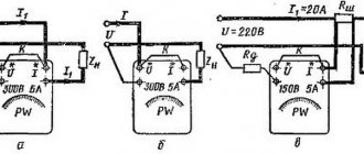
The essence of the indirect power measurement method is to measure the voltage U and current I of the circuit using a voltmeter and ammeter and then calculate it in accordance with expression (2). In Fig. 1 shows two possible schemes for connecting a voltmeter and an ammeter to a circuit when measuring the power consumed by the load RH,
For circuit 1,
and
the power consumed by the circuit is:
P = U(IN + IB) = UН + UIB = PH + PB,
where IN and IV are currents flowing through the load and voltmeter, respectively; RN and PB are the power consumed by the load and the voltmeter, respectively.
Thus, for a given switching circuit, the calculated power value P
will be greater than the actual value of power consumed by the load
RN
by the amount
РВ
=
UIB.
In this case, the error in determining the power consumed by the load will be smaller, the lower the current IV compared to IN, i.e., the greater the input resistance of the voltmeter (RV)
.
Consumption by the circuit (Fig. 1, b)
power is equal to:
R
=
UIH
= (UH+IHRа)IH=PH+Pa,
i.e. the power determined by the calculation will be greater than the actual load power PH by the amount of power loss in the ammeter Pa=IHRа. The smaller the ammeter resistance is compared to the load resistance, the smaller the error in determining the power consumed by the load.
The analysis shows that the power measurement error will be minimal when the measuring instruments are switched on according to the diagram shown in Fig. 1,a, if the condition is met
(3)
When turning on the devices according to the diagram shown in Fig. 1, b, the measurement error will be minimal provided
(4)
For accurate measurements, the mentioned error can be taken into account if the resistance of the measuring instruments is known.
Rice. 1
For a known load resistance RH
the power Pa it consumes is determined by measuring the current In flowing through it or the voltage drop across it Un
.
Power calculation is made in accordance with the expressions:
The considered methods for determining the power consumed by the load are also used when measuring the power of DC generators.
Measuring power in a direct current circuit by the direct method is mainly carried out using wattmeters of an electrodynamic system.
The measuring mechanism of the wattmeter of the electrodynamic system, consisting of a fixed coil and a moving coil located inside it, is connected to a direct current circuit according to the diagram shown in Fig. 2. The fixed (current) coil is connected in series with the load, and the moving coil is connected in parallel to the load. The additional resistance Rd, connected in series with the moving coil, is intended to expand the voltage measurement limit of the device. As a result of the interaction of the magnetic fields of the coils, a torque is created:
where I1 and I2 are the currents flowing through the fixed and moving coils, respectively; f(α)
- a function that takes into account the change in torque depending on the angle of rotation a of the moving coil (due to a change in the mutual induction between the coils).
The counteracting moment is created by the conductive springs of the moving coil
where W
— specific counteracting moment of the springs.
| Rice. 2 | If the rotating and counteracting moments are equal, the moving coil will rotate through a certain angle a, determined from the expression Since then |
Here R2 is the resistance of the moving coil; — constant value; P = IHU - power consumed by the load.
In order for the instrument scale to be uniform, it is necessary to ensure the constancy of the function f
(α). This is achieved by appropriate selection of the size and shape of the coils and their initial relative position.
When connecting the wattmeter to a DC circuit, the polarity of the coil connections must be observed. To do this, two of the four terminals of the device, corresponding to the “beginning” of the moving and fixed coils, are indicated by asterisks (*) or a plus sign (+). These terminals must be connected to the positive pole of the power source (to the generator - generator terminals), and not to the load.
In Fig. Figure 3 shows two diagrams for connecting a wattmeter to a DC circuit. When you turn on the device according to the diagram shown in Fig. 3, a ,
the power source voltage U is applied to the moving coil and is greater than the voltage across the load resistance U by the amount of voltage drop across the fixed coil, i.e. the wattmeter reading will be greater than the actual value of the load power. In this case, the lower the resistance of the current coil compared to the load resistance, the smaller the power measurement error will be. When you turn on the device according to the diagram shown in Fig. 3, b, the current flowing through the load will be less than the current in the current coil by the amount of current flowing through the moving coil, i.e. the device reading will be greater than the actual value of the power consumed by the load. The error in measuring the power consumed by the load will be smaller, the greater the resistance of the moving coil with the series-connected additional resistance Rd of the load resistance Rn.
Rice. 3
With both the indirect and direct methods of measuring power, the measurement result differs from the actual value of power consumed by the load by a certain systematic error. The magnitude of the systematic error is determined by the connection circuit of the wattmeter and the resistance of its coils.
The error in power measurement when the wattmeter is turned on according to the circuit shown in Fig. 3, a
, will be minimal if condition (3) is met, and in this case the resistance of the fixed coil is taken as Ra, and the resistance of the moving coil with a series-connected additional resistance Rd is taken as RB. When the wattmeter is turned on according to the diagram (Fig. 3, b), the error will be minimal if condition (4) is met.
Power measurement of direct and alternating single-phase current
From the expression for direct current power P = IU it can be seen that it can be measured using an ammeter and voltmeter by an indirect method.
However, in this case it is necessary to carry out simultaneous readings from two instruments and calculations, which complicate the measurements and reduce its accuracy. To measure power in direct and single-phase alternating current circuits, instruments called wattmeters are used, for which electrodynamic and ferrodynamic measuring mechanisms are used.
Electrical power measurement
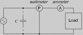
Electrical power is measured by a wattmeter - a device that has two windings: current and voltage (Fig. 7).
The wattmeter scale is graduated in watts or kilowatts.
Extension of the measurement limits at direct current voltage is carried out using additional resistances - shunts. When measuring on alternating current, the limits are expanded using current and voltage transformers (Fig. 8). In this case, it is necessary to ensure that the generator terminals (*) of the wattmeter are connected correctly.
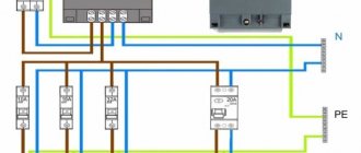
Power measurement in three-phase three-wire networks is carried out using two single-phase wattmeters connected in two phases according to the diagram (Fig. 9). In three-phase four-wire networks, active power is measured using three single-phase wattmeters (Fig. 10) or one three-element wattmeter.
Extension of measurement limits is carried out using current and voltage transformers. In these same networks, a three-phase wattmeter is used to measure power (Fig. 11).
Rice. 7. Connection diagram for a single-phase wattmeter
:
1 - serial (current) coil;
2 - parallel (voltage) coil; rg - additional resistance Fig. 8. Circuit diagram for connecting a wattmeter using current and voltage transformers
Rice. 9. Scheme for measuring active power in a three-phase three-wire network with two wattmeters: Ptotal = P1 + P2
Rice. 10. Scheme for measuring active power in a three-phase four-wire network with three wattmeters: Ptotal = P1 + P2 + P3
Rice. 11. Connection diagram of a three-phase ferrodynamic wattmeter
Current, voltage and power measurements
Current measurement . Ammeters are used to measure current. The ammeter is connected to the circuit in such a way that the entire measured current passes through it, i.e. sequentially. Therefore, its resistance should be small compared to the resistance of the circuit.
To measure direct current, devices of the magnetoelectric system are used, less often devices of the electromagnetic system. To measure alternating current with a frequency of 50 Hz, electromagnetic system devices are mainly used. The resistance of these devices ranges from a fraction of an ohm to several ohms.
To expand the measurement limits of ammeters in DC circuits, shunts are used. Their resistance is calculated using the formula:
where I
an is the rated current value of the ammeter;
R
a is the internal resistance of the ammeter;
I
w is the current passing through the shunt.
To expand the measurement limits of ammeters in alternating current circuits, measuring current transformers are used.
Voltage measurement. Voltmeters are used to measure voltage.