DC Power
Definitions and formulas
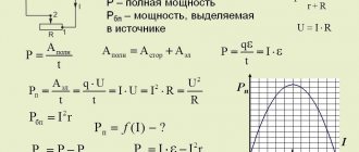
Power is the work produced per unit of time. Electrical power is equal to the product of current and voltage: P=U∙I. From here we can derive other formulas for power:
We obtain the power unit by substituting the units of voltage and current into the formula:
The unit of electrical power equal to 1 VA is called watt (W). The name volt-ampere (VA) is used in alternating current engineering, but only to measure apparent and reactive power.
The units of measurement of electrical and mechanical power are related by the following relationships:
1 W =1/9.81 kg•m/sec ≈1/10 kg•m/sec;
1 kg•m/sec =9.81 W ≈10 W;
1 hp =75 kg•m/sec =736 W;
1 kW =102 kg•m/sec =1.36 hp.
If we do not take into account the inevitable energy losses, a 1 kW motor can pump 102 liters of water every second to a height of 1 m or 10.2 liters of water to a height of 10 m.
1. The heating element of an electric furnace with a power of 500 W and a voltage of 220 V is made of high resistance wire. Calculate the resistance of the element and the current that passes through it (Fig. 1).
We will find the current using the electric power formula P=U∙I,
whence I=P/U=(500 Bm)/(220 V)=2.27 A.
Resistance is calculated using another power formula: P=U^2/r,
whence r=U^2/P=(220^2)/500=48400/500=96.8 Ohm.
2. What resistance should the spiral (Fig. 2) of the tile have at a current of 3 A and a power of 500 W?
For this case, we apply another power formula: P=U∙I=r∙I∙I=r∙I^2;
hence r=P/I^2 =500/3^2 =500/9=55.5 Ohm.
3. What power is converted into heat with a resistance of r=100 Ohm, which is connected to a network with a voltage of U=220 V (Fig. 3)?
4. In the diagram in Fig. 4, the ammeter shows current I = 2 A. Calculate the consumer resistance and the electrical power consumed in the resistance r = 100 Ohms when it is connected to a network with a voltage of U = 220 V.
P=U∙I=220∙2=440 W, or P=U^2/r=220^2/110=48400/110=440 W.
5. The lamp only indicates its nominal voltage of 24 V. To determine the remaining data of the lamp, we will assemble the circuit shown in Fig. 5. Let’s adjust the current with the rheostat so that the voltmeter connected to the lamp terminals shows voltage Ul = 24 V. The ammeter shows current I = 1.46 A. What power and resistance does the lamp have and what voltage and power losses occur at the rheostat?
Lamp power P=Ul∙I=24∙1.46=35 W.
Its resistance is rл=Uл/I=24/1.46=16.4 Ohm.
Voltage drop across the rheostat Uр=U-Uл=30-24=6 V.
Power losses in the rheostat Pр=Uр∙I=6∙1.46=8.76 W.
6. The electrical furnace’s panel indicates its nominal data (P=10 kW; U=220 V).
Determine what resistance the furnace represents and what current passes through it during operation P=U∙I=U^2/r;
r=U^2/P=220^2/10000=48400/10000=4.84 Ohm; I=P/U=10000/220=45.45 A.
7. What is the voltage U at the terminals of the generator if, at a current of 110 A, its power is 12 kW (Fig. 7)?
Since P=U∙I, then U=P/I=12000/110=109 V.
8. In the diagram in Fig. Figure 8 shows the operation of electromagnetic current protection. At a certain current, the electromagnet EM, which is held by spring P, will attract the armature, open contact K and break the current circuit. In our example, current protection breaks the current circuit at a current I≥2 A. How many 25 W lamps can be simultaneously turned on at a mains voltage of U=220 V so that the limiter does not work?
The protection is triggered at I=2 A, i.e. at power P=U∙I=220∙2=440 W.
Dividing the total power of one lamp, we get: 440/25=17.6.
17 lamps can be lit at the same time.
9. An electric oven has three heating elements with a power of 500 W and a voltage of 220 V, connected in parallel.
What is the total resistance, current and power when the furnace is operating (Fig. 91)?
Total furnace power P=3∙500 W =1.5 kW.
Resulting current I=P/U=1500/220=6.82 A.
The resulting resistance is r=U/I=220/6.82=32.2 Ohm.
Current of one element I1=500/220=2.27 A.
Resistance of one element: r1=220/2.27=96.9 Ohm.
10. Calculate the resistance and current of the consumer if the wattmeter shows a power of 75 W at a network voltage of U = 220 V (Fig. 10).
Since P=U^2/r, then r=U^2/P=48400/75=645.3 Ohm.
Current I=P/U=75/220=0.34 A.
11. The dam has a water level difference h=4 m. Every second, 51 liters of water enters the turbine through the pipeline. What mechanical power is converted into electrical power in the generator, if losses are not taken into account (Fig. 11)?
Mechanical power Pm=Q∙h=51 kg/sec ∙4 m =204 kg•m/sec.
Hence the electrical power Pe=Pm:102=204:102=2 kW.
12. What power should the pump motor have that pumps 25.5 liters of water every second from a depth of 5 m into a tank located at a height of 3 m? Losses are not taken into account (Fig. 12).
The total height of water rise h=5+3=8 m.
Mechanical power of the engine Pм=Q∙h=25.5∙8=204 kg•m/sec.
Electric power Pe=Pm:102=204:102=2 kW.
13. A hydroelectric power station receives 4 m3 of water from a reservoir per turbine every second. The difference between the water levels in the reservoir and the turbine is h=20 m. Determine the power of one turbine without taking into account losses (Fig. 13).
Mechanical power of flowing water Pm=Q∙h=4∙20=80 t/sec•m; Pm=80000 kg•m/sec.
Electric power of one turbine Pe=Pm:102=80000:102=784 kW.
14. In a parallel-wound DC motor, the armature winding and the field winding are connected in parallel. The armature winding has a resistance of r=0.1 Ohm, and the armature current I=20 A. The excitation winding has a resistance of rв=25 Ohm, and the excitation current is equal to Iв=1.2 A. What power is lost in both windings of the motor (Fig. 14 )?
Power loss in the armature winding P=r∙I^2=0.1∙20^2=40 W.
Power losses in the field winding
Total losses in the motor windings P+Pv=40+36=76 W.
15. An electric stove with a voltage of 220 V has four switchable heating stages, which is achieved by varying the inclusion of two heating elements with resistances r1 and r2, as shown in Fig. 15.
Determine the resistances r1 and r2 if the first heating element has a power of 500 W, and the second 300 W.
Since the power released in the resistance is expressed by the formula P=U∙I=U^2/r, then the resistance of the first heating element
and the second heating element r2=U^2/P2 =220^2/300=48400/300=161.3 Ohm.
In the stage IV position, the resistances are connected in series. The power of the electric stove in this position is equal to:
P3=U^2/(r1+r2)=220^2/(96.8+161.3)=48400/258.1=187.5 W.
In the stage I position, the heating elements are connected in parallel and the resulting resistance is equal to: r=(r1∙r2)/(r1+r2)=(96.8∙161.3)/(96.8+161.3)=60.4 Ohm.
Tile power in stage I position: P1=U^2/r=48400/60.4=800 W.
We get the same power by adding up the powers of individual heating elements.
16. A lamp with a tungsten filament is designed for a power of 40 W and a voltage of 220 V. What resistance and current does the lamp have in a cold state and at an operating temperature of 2500 ° C?
Lamp power P=U∙I=U^2/r.
Hence the resistance of the lamp filament in a hot state is rt=U^2/P=220^2/40=1210 Ohm.
The resistance of the cold thread (at 20 °C) is determined by the formula rt=r∙(1+α∙∆t),
whence r=rt/(1+α∙∆t)=1210/(1+0.004∙(2500-20) )=1210/10.92=118 Ohm.
A current I=P/U=40/220=0.18 A passes through the lamp filament when hot.
The switch-on current is: I=U/r=220/118=1.86 A.
When turned on, the current is approximately 10 times greater than the hot lamp current.
17. What are the voltage and power losses in the copper contact wire of an electrified railway (Fig. 16)?
Mechanical characteristics of DC motors
An analytical expression for the mechanical characteristics of a DC motor can be obtained from the armature circuit voltage equilibrium equation (at steady state)
where U
— voltage at the motor terminals, V;
1I
- current in the armature circuit, A;
Rya
- armature circuit resistance, Ohm; F is the magnetic flux of the motor, Wb; ω—angular velocity of the armature, rad/s; sd is a coefficient depending on the design data of the engine. Having solved equation (3.1) with respect to angular velocity, we obtain the equation for the speed characteristics of the engine
The electromagnetic torque of the motor (N • m) is proportional to the magnetic flux and armature current:
From equation (3.3) armature current
Substituting the current value expressed by equation (3.4) into equation (3.2), we obtain the equation for the mechanical characteristics of DC motors, regardless of the excitation method
Let's consider the mechanical characteristics of DC motors depending on the excitation method.
Parallel-excited DC motors. The connection diagram for a parallel-excited DC motor is shown in Fig. 3.1, a. Excitation winding OB
can be connected to the same network as the armature, or to a separate current source (independent excitation). In both cases, the excitation current does not depend on the processes occurring in the motor armature and at a constant network voltage, the magnetic flux can be considered constant Ф = const. Denoting sdF = kd and substituting it into equation (3.5), we obtain the equation for the mechanical characteristics of a parallel-excited DC motor
When M=0
anchor angular velocity
called the ideal idle speed.
The second term of equation (3.6) determines the change in the angular velocity of the engine when the torque changes
The value of Δω depends not only on the torque, but also on the resistance of the armature circuit. With increasing R, the value of Δω increases. Taking into account equations (3.7) and (3.8), equation (3.6) can be written in the form
From equations (3.6) and (3-.9) it is clear that the mechanical characteristic of a parallel-excitation motor is a straight line, the slope of which is determined by the value R
i/kd2
In Fig. 3.1.6 shows the natural and artificial mechanical characteristics obtained by introducing a rheostat into the armature circuit. Such artificial characteristics are used when starting and braking the engine.
Series-excited DC motors. The circuit diagram for connecting a series excitation motor is shown in Fig. 3.2, a.
The OB
is connected in series with the armature and the armature current flows through it. Therefore, the motor flux is a function of the armature current. This dependence is expressed graphically in the form of a magnetization curve, which is a nonlinear function and has no analytical expression. Therefore, it is impossible to obtain an analytical dependence for the mechanical characteristic.
A characteristic feature of series-excited motors is that a change in magnetic flux with a change in armature current has a great influence on the speed of the motor. This is clearly seen from the speed characteristic equation
which shows that with a change in magnetic flux, the speed of the motor can vary within wide limits.
If, for simplicity, we assume that the magnetic circuit of the motor is not saturated and the flux is proportional to the current
F = sf/I,
then the engine torque
where k = cd / sf.
Substituting the value Ф = Сф/я into the equation of the speed characteristic, we obtain
where R
- internal resistance of the armature circuit, equal to the sum of the resistances of the armature and excitation windings
(Rya + rya).
Replacing the armature current in the equation with its expression from (3.10), we obtain the equation of the mechanical characteristic
Equation (3.12) is the equation of a curve for which the y-axis is an asymptote. A similar characteristic is shown in Fig. 3.2,6. Equation (3.12) gives only a general idea of the mechanical characteristics of the engine. It cannot be used in calculations, since it is impossible to analytically take into account the magnetization of steel. As can be seen in Fig. 3.2.6, the mechanical characteristics of the sequential excitation motor are soft. As the load decreases, the angular velocity increases sharply, and at M = 0
it tends to infinity. In real engines, the no-load current cannot be zero due to losses in steel and mechanical losses, but the angular velocity can reach values that are dangerous in terms of mechanical strength, equal to (5÷6)ωnom. Therefore, idling for series-excited motors is unacceptable.
Mixed-excitation DC motors. Mixed-excitation motors have two excitation windings (Fig. 3.3). The magnetic flux of the motor is determined by the sum of the parallel fluxes
and serial OVOS
windings:
Due to the nonlinear dependence of the magnetic flux on the armature current, an analytical expression for the mechanical characteristics, as well as for a series-excited motor, cannot be obtained.
Depending on the ratio of the magnetic fluxes of the excitation windings, the mechanical characteristics have different rigidity. The larger the proportion of magnetic flux of the series winding, the softer the characteristic. In Fig. 3.3 shows two natural characteristics with different ratios of magnetic fluxes of the field windings. The parallel excitation winding creates a flux Fpar independent of the armature current, so the motor can idle at speed
Previous2Next
WHAT IS CONFIDENT BEHAVIOR IN INTERPERSONAL RELATIONSHIPS? Historically, there are three main patterns of differences that exist between...
WHAT AND HOW THEY WRITTEN ABOUT FASHION IN MAGAZINES AT THE BEGINNING OF THE XX CENTURY The first issue of the Apollo magazine for 1909 began, in fact, with a policy statement from the magazine’s editors...
WHAT HAPPENS WHEN WE FIGHT Without understanding the differences that exist between men and women, it is very easy to lead to a quarrel...
WHAT HAPPENS IN ADULT LIFE? If you are still connected to your mother in the wrong way, you are avoiding separation and independent adult existence...
Didn't find what you were looking for? Use Google search on the site:
Calculation formulas for DC machine parameters
Table 1 presents calculation formulas for determining the main parameters of DC machines .
This table contains all the formulas that relate to calculating the parameters of DC machines.
Table 1 - Calculation formulas for determining the main parameters of DC machines
1. Electrician's reference book. IN AND. Grigorieva, 2004
Share on social networks
If you have found the answer to your question and you want to thank the author of the article for his work, you can use the platform for transferring funds “WebMoney Funding”.
This project is supported and developed exclusively with funds from voluntary donations.
By showing loyalty to the site, you can transfer any amount of money, thereby you will help improve this site, increase the regularity of new interesting articles and pay for regular expenses, such as: payment for hosting, domain name, SSL certificate, salary to our authors.
The choice of surge voltage protection device (SPD) must be carried out in accordance with.
I present to your attention a table with calculation formulas that are used to calculate losses.
In this example, it is required to select support insulators for the previously selected 10 kV busbars. Original.
In this example, it is required to determine the maximum voltage losses in normal and emergency modes.
The choice of capacitor voltage for a capacitor motor is no less important than the definition.
By sending a message, you consent to the collection and processing of personal data. Privacy Policy.
Source
Electromagnetic torque of a DC machine.
A torque always occurs if a current flows in the winding, and it itself is in a magnetic field. However, the role of the electromagnetic torque in the generator and the engine is different. In the engine the moment is rotational, and in the generator it is braking, i.e. counteracting the rotation of the armature. Therefore, it is often said that the generator operates in braking torque mode, and the engine in counter-EMF mode.
Armature reaction of a DC machine.
The effect of the magnetizing force of the armature on the main field is called the armature reaction.
In a machine, the resulting field is one, it is determined by the combined action of the main field (created by the excitation coils) and the field from the armature reaction.
The armature reaction occurs when the machine is operating under load. The manifestation of the reaction depends on the operating mode (engine or generator):
1) From the position of the brushes relative to the geometric neutral
2) From saturation of the magnetic circuit
The armature reaction distorts the main field of the machine. The armature reaction can reduce the main field of the machine if the magnetic circuit is saturated.
A radical means of reducing the armature reaction is to install a compensation winding, which is placed in the grooves of the main pole shoes and connected in series with the armature winding. But so that its magnetizing force is directed opposite to the magnetizing force of the armature. Then the resulting curve will be similar to the curve at idle.
The compensation winding is a radical means of eliminating the distorting effect of the armature reaction.
Another, less radical means of weakening the armature reaction is to increase the gap under the edges of the main poles.
Switching of DC machines.
Commutation is a set of processes associated with a change in current in the armature section when it moves from one parallel branch to another. This process occurs under the brush. This process is accompanied by sparking. Sparking is classified by GOST.
Switching calculation - switching.
For sparking GOST 183-74.
Causes of sparking:
- Mechanical
- Electromagnetic nature
- Potential nature
еср – average interlamella tension.
< 21 V
Under unfavorable circumstances, sparking can develop into a circular fire on the manifold and cause a serious accident. A circular fire is an electric arc that covers the collector partially or completely.
The duration of the switching process is estimated by the switching period:
Example: β – how many collector plates the brush covers.
; ; 2.5 – 4.5;
n = 720 rpm = 12 rps; k=300;
c
Calculation of basic engine parameters from the nameplate
Electric motors are found everywhere in industry and everyday life. If you haven’t paid attention, I’ll give you a couple of photo examples:
Sometimes a need arises, born of everyday curiosity, or a production need, to determine the power of an electric motor by its appearance, or the permissible operating temperature, not to mention the current and voltage values.
Here it is possible that the plate on which the nominal parameters are written has been torn off, or the nameplate is in such a state that it is impossible to distinguish anything. How to be in such a situation...
It’s one thing if you’ve worked in engine production all your life and can determine the power by eye. In other cases, a ruler (tape measure) and tables with the dimensions of the mechanisms will help determine.
If your activity lies more in theoretical research than practical, then a formula for determining the power of an electric motor or a table with nominal data will be useful, this is exactly what this article is about and not only.
Electric motor label
Having examined any electric motor, with rare exceptions, you can find a plate screwed onto bolts, screws or rivets. What is written on this piece of metal? Let's take a nameplate, replacing the serial number on it with the name of the site.
By the way, it rarely happens that a plate for electrical equipment is in such almost perfect condition. Often the data is faded or covered with paint, because the task is for the maintenance personnel to paint the engine, and not to paint the engine, leaving the plate untouched. But we were lucky. Let's go in order.
First line
- number of phases and type of current (3
), serial number, network frequency, design and installation form, insulation class
Second line
— type of electric motor, cosine phi, possible connection diagrams, rated speed
Third line
- possible rated voltages, rated power, IP - degree of protection of the electric motor, weight, operating mode of the electric motor (S1).
Fourth line
- rated currents depending on the winding connection circuit, then which guest the ed corresponds to.
Let's look at the individual parameters in more detail.
Electric motor power: total, active and shaft
Formula for calculating the power of a three-phase asynchronous motor:
S1 - total power consumed by the motor from the network
P1 - active power consumed by the electric motor from the network (indicated on the nameplate)
P is the active power on the EM shaft.
cosf - cosine phi, power factor - phase angle between active (P) and total power (S).
In the formulas above, the power value is obtained in W, the total power value in VA. To convert to kilowatts, you need to divide the resulting value by a thousand. The value of current and voltage, respectively, in the formula above is in amperes and volts.
I1 and U1 are linear values of current and voltage, they are also called phase-to-phase. Not to be confused with phase ones. Linear ones are AB, BC, SA (380); phase - AO, VO, SO (220). If we express the power formulas in terms of the phase values of current and voltage, then instead of the root of three there will initially be a coefficient of 3. This coefficient is determined visually through the vector diagram of the three-phase voltage.
For DC motors, the formula will simply be the voltage at the motor terminals multiplied by the current drawn by the motor from the network.
Power consumption p1 is greater than the power on the EM shaft due to losses that arise when converting electrical energy into mechanical energy.
Star/Delta and 220/380, 380/660
See all the values in order as they go through the fraction. That is, it is written on the nameplate Y/D (triangle/star), which means that the currents and voltages will accordingly be first for Y, and after the fraction for the star. The only caveat is that at 220/380 the triangle will be 220, and at 380/660 the triangle will be 380. That is, to say that 380 is always a star is incorrect.
Always read the label on the engine before connecting.
The advantages of star and delta connections are abstract, since each circuit has its own areas of application:
- Y - less operating and starting current, more voltage, less starting torque, less heat
- D - higher starting torque, starting current, but also heats up more.
There are two-speed engines, where they first start on a star, and then switch to a triangle. In this case, the mechanism starts up easier and then works with more power.
When connecting a three-phase 220V motor, where there is only a phase and a zero, you can resort to a circuit with capacitors.
Execution form and installation method
IM 1081 - form of execution and installation method in accordance with GOST 2479 and IEC60034-5. In our example, this means “foot-mounted with two end shields, with one cylindrical shaft end.”
Electric motor power calculation
The conversion of electrical energy into kinetic energy is carried out using various types of electric motors. Most often, electric motors serve as electric drives for machines and mechanisms and are used to ensure the operation of pumping equipment, ventilation systems and many other units and devices. In connection with such a wide application, the calculation of electric motor power is of particular relevance. For these purposes, many different methods have been developed that allow calculations to be performed in relation to specific operating conditions.
- Main types of electric motors
- Calculation of electric motor power for a pump
- Calculation of engine power formula for compressor
- Calculation formula for fans
- Calculation of motor starting current
- Operating modes of electric motors
Basic parameters of a DC motor
Torque constant
,
Constant EMF
The direction of the EMF is determined by the right-hand rule. The direction of the induced emf is opposite to the direction of the current flowing in the conductor.
The induced EMF consistently changes in direction due to the movement of conductors in a magnetic field. The total emf, equal to the sum of the emf in each coil, is applied to the external terminals of the motor. This is back-EMF. The direction of the back EMF is opposite to the voltage applied to the motor. The value of the back-EMF is proportional to the rotation speed and is determined from the following expression: [1]
,
The torque and EMF constants are exactly equal to each other KT = KE. The constants KT and KE are equal to each other if they are defined in a single system of units.
Motor constant
One of the main parameters of a DC electric motor is the electric motor constant Km. Motor constant determines the ability of an electric motor to convert electrical energy into mechanical energy.
Main types of electric motors
There are many types and modifications of electric motors. Each of them has its own power and other parameters.
The main classification divides these devices into DC and AC motors. The first option is used much less frequently, since its operation requires the presence of a direct current source or a device that converts alternating voltage into direct current. Fulfilling this condition in modern production will require significant additional costs.
But, despite significant disadvantages, DC motors have a high starting torque and operate stably even at high overloads. Due to their qualities, these units are widely used in electric transport, in the metallurgical and machine tool industries.
However, most modern equipment runs on AC motors. The operation of these devices is based on electromagnetic induction, which is created in a magnetic field by a conducting medium. The magnetic field is created using windings flowing around currents or using permanent magnets. Electric motors operating on alternating current can be synchronous or asynchronous.
The use of synchronous electric motors is practiced in equipment where a constant rotation speed is required. These are DC generators, pumps, compressors and other similar installations. Different models differ in their own technical characteristics. For example, the rotation speed can be in the range of 125-1000 rpm, and the power reaches 10 thousand kilowatts.
Many designs have a short-circuited winding located on the rotor. With its help, if necessary, an asynchronous start is made, after which the synchronous motor continues to operate as usual, minimizing electrical energy losses. These engines are characterized by their small size and high efficiency.
Asynchronous AC motors have become much more widespread in the manufacturing sector. They are characterized by a very high frequency of rotation of the magnetic field, significantly exceeding the speed of rotation of the rotor. A significant disadvantage of these devices is considered to be a decrease in efficiency to 30-50% of the norm at low loads. In addition, during start-up, the current parameters become several times greater compared to operating indicators. These problems are eliminated by using frequency converters and soft starters.
Asynchronous motors are used in those facilities where frequent switching on and off of equipment is required, for example, in elevators, winches, and other devices.
7.4. EMF AND ELECTROMAGNETIC TORQUE OF DC GENERATOR
As already noted, the EMF induced in the winding of the rotating armature of the generator is proportional to the magnetic flux of the poles and the frequency of its rotation:
The magnetic flux in the generator, as is known, is created by the excitation current Iв. If you rotate the armature with a constant frequency n and continuously measure the output emf E, then you can plot a graph E = f (Iв) (Fig. 7.4.1).
This dependence is called the idle speed characteristic.
It is built for a mode when the generator has no external load, i.e. running idle. If you connect a load to the generator, the voltage at its terminals will be less than E by the value of the voltage drop in the armature circuit:
Here: U is the voltage at the terminals; E - EMF in idle mode; IА - armature current; RI is the resistance in the armature circuit. The voltage drop in the armature circuit usually does not exceed 2-8% of the generator's emf. The decrease in voltage at the generator output is associated with demagnetization of the machine by the magnetic field of the armature, as well as a drop in voltage in its windings. In every direct current machine, there is an interaction between the armature current IА and the magnetic flux F. As a result, an electromagnetic force acts on each conductor of the armature winding:
where B is magnetic induction, IА is the current in the armature winding, L is the length of the armature. The direction of this force is determined by the left-hand rule. Let us substitute here the average value of the magnetic induction of the HRV and the magnitude of the current in each conductor of the armature winding I = IА / 2 a. We get
Electromagnetic torque acting on the machine armature, with the number of winding conductors N:
where is a constant value for a given machine; d—anchor diameter; p—number of pole pairs; N is the number of conductors of the armature winding; a is the number of pairs of parallel branches. When the machine operates in generator mode, the electromagnetic torque acts against the rotation of the armature, i.e. is inhibitory. To drive a generator, an electric motor requires power, which must cover all losses in the generator:
where P is the useful electrical power of the generator; DРЯ - losses in the armature winding; DРВ - losses in the excitation winding; DРМ - losses due to magnetization of the machine; DРМЭХ - mechanical losses associated with friction of rotating parts.
The efficiency of the generator is determined by the ratio:
Modern DC generators have an efficiency of 90-92%.
Calculation of electric motor power for a pump
The choice of electric motor for a pumping installation depends on specific conditions, first of all, on the water supply scheme. In most cases, water is supplied using a water tank or a water boiler. Centrifugal pumps with asynchronous motors are used to drive the entire system.
The selection of the optimal pump power is carried out depending on the need for fluid supply and pressure. The QH pump flow is measured in liters delivered per hour and is designated as l/h. This parameter is determined by the following formula: Qn = Qmaxch = (kch x kday x Qav.day) / (24 η), where Qmaxch is the possible maximum hourly water flow rate, l/h, kch is the coefficient of unevenness of hourly flow, kday is the coefficient of unevenness daily flow rate (1.1 - 1.3), η - efficiency of the pumping unit, taking into account water losses), Qavg.day - value of the average daily water flow rate (l/day).
The optimal water pressure should ensure its supply to the specified location, subject to the required pressure. The required parameters of the pump pressure (Hntr) depend on the suction height (Hvs) and the discharge height (Nng), which together determine the indicators of static pressure (Hs), losses in pipelines (Hp) and the pressure difference between the upper (Pvu) and lower (Pnu) levels.
Based on the fact that the pressure value will be equal to H = P/ρg, where P is pressure (Pa), ρ is the density of the liquid (kg/m3), g = 9.8 m/s2 is the acceleration of free fall, g is the specific liquid weight (kg/m3), the following formula is obtained: Hntr = Hc + Hp + (1/ρ) x (Pvu – Rnu).
After calculating the water flow and pressure from the catalog, you can already select a pump with the most suitable parameters. In order not to be mistaken with the power of the electric motor, it must be determined by the formula: Pmod = (kз x ρ x Qн x Нн) / (ηн x ηп), where kз is a safety factor depending on the power of the pump motor and is 1.05 – 1, 7. This indicator takes into account possible water leaks from the pipeline due to loose connections, pipeline breaks and other factors, so electric motors for pumps must have some power reserve. The higher the power, the lower the safety factor can be assumed.
Calculation of engine power formula for compressor
When choosing an electric motor that is most suitable for the operation of a particular compressor, it is necessary to take into account the long-term operation of this mechanism and the constant load. The required power of the RDV engine is calculated in accordance with the power on the shaft of the main mechanism. In this case, the losses arising in the intermediate link of the mechanical transmission should be taken into account.
Additional factors are the capacity, purpose and nature of the production where the compressor equipment will be operated. They have an impact and the equipment may require minor but ongoing adjustments to maintain proper performance.
The engine power can be determined using the formula:
, wherein:
- Q – compressor performance or flow value (m 3 /s);
- A – work to perform compression (J/m 3 );
- ηк – indicator efficiency (0.6-0.8) to take into account power losses during real air compression;
- ηп – mechanical efficiency (0.9-0.95) taking into account the transmission between the engine and the compressor;
- kz – safety factor (1.05-1.15) to take into account factors that cannot be calculated.
Work A is calculated using a separate formula: A = (Au + Aa)/2, where Au and Aa represent isothermal and adiabatic compression, respectively.
The value of the work that must be done before the required pressure appears can be determined using the table:
Typical compressor operation is characterized by continuous operation. Reversible electric drives, as a rule, are absent; switching on and off is extremely rare. Therefore, the most optimal option to ensure normal operation of compressors would be a synchronous electric motor.
7.5. DC MOTOR
According to the principle of reversibility, a DC machine can operate both as a generator and as a motor. The EMF equation for the motor is based on Kirchhoff’s 2nd law, taking into account the direction of the EMF:
In accordance with the formula Ea = Ce Ф n, the rotation speed is determined by the expression:
Substituting the value of E from the equation U = E - IЯ RЯ, we get:
those. The engine speed is directly proportional to the applied voltage and inversely proportional to the excitation magnetic flux. From this formula it can be seen that there are possible ways to regulate the rotation speed of a DC motor: 1. By changing the network voltage U. By adjusting the supplied voltage U, you can change the rotation speed. 2. By including additional resistance in the armature circuit (R'Я = RЯ + RADOB). By changing the resistance RDOB, the rotation speed is changed. 3. By changing the magnetic flux F. Machines with permanent magnets are not regulated. Machines with electromagnets make it possible to regulate the flow Ф by changing the excitation current IB. In Fig. 7.5.1. shows a diagram of connecting a DC motor to the network.
According to the law of electromagnetic induction, when current passes through the armature winding, its conductors interact with the magnetic field of the poles. Each conductor of the winding will be subject to an electromagnetic force Rem = BCPLI, proportional to the magnetic induction of the poles B, the length of the conductor L and the current I flowing through the conductor. The direction of this force is determined by the right hand rule. Without repeating the reasoning carried out for the DC generator, we write down the expression for the torque:
where CM is the proportionality coefficient. The torque of motors with independent and parallel excitation can either increase or decrease with increasing load, since with increasing current consumption I and pole demagnetization, magnetic flux F decreases.
Series-wound motors have different characteristics from the above motors. From the diagram shown in Fig. 7.2.1c, it is clear that the magnetic flux in the machine is created by an excitation winding connected in series with the armature winding. Therefore, IB = IА and the expression for the torque will be:
The last formula shows that the greater the load on the engine, the greater the torque will be. This circumstance makes a motor with sequential excitation indispensable in electric transport (trams, trolleybuses, etc.). Reversing or changing the direction of rotation of DC motors can be accomplished by changing the polarity of the current either in the armature winding or in the field winding.
Calculation formula for fans
Fans are widely used in a variety of fields. General purpose devices operate in clean air, at temperatures below 80°C. Air with a higher temperature is moved using special heat-resistant fans. If you have to work in an aggressive or explosive environment, in these cases models of anti-corrosion and explosion-proof devices are used.
In accordance with the principle of operation, fan units can be centrifugal or radial and axial. Depending on the design, they develop pressure from 1000 to 15000 Pa. Therefore, the power required to drive the fan is calculated in accordance with the pressure that needs to be created.
For this purpose, the formula is used: Nв=Hв·Qв/1000·efficiency, in which Nв is the power required for the drive (kW), Hв is the pressure created by the fan (Pa), Qв is the moved volume of air (m 3 /s) , efficiency – efficiency factor.
To calculate the power of an electric motor, the formula is used:
, where the parameter values will be as follows:
- Q – unit productivity;
- Н – outlet pressure;
- ηв – fan efficiency;
- ηп – transmission efficiency;
- short – safety factor depending on the power of the electric motor. With a power of up to 1 kW, short circuit = 2; from 1 to 2 kW short circuit = 1.5; at 5 kW and above short circuit = 1.1-1.2.
This formula allows you to calculate the power of electric motors for centrifugal and axial fans. For centrifugal structures, the efficiency is 0.4-0.7, and for axial ones - 0.5-0.85. Other design characteristics are available in special catalogs for all types of electric motors.
The power reserve should not be too large. If it is too large, the efficiency of the drive will noticeably decrease. In addition, AC motors may experience a reduction in power factor.
Calculation of motor starting current
When the electric motor starts, its shaft remains stationary. In order for it to begin to unwind, it is necessary to apply a force significantly greater than the nominal one. In this regard, the starting current also exceeds the nominal value. As the shaft unwinds, the current gradually decreases smoothly.
The influence of inrush currents negatively affects the operation of equipment, mainly due to sudden voltage dips. In order to reduce their negative impact, various methods are used. During the acceleration process, the electric motor circuits are switched from star to delta, frequency converters and electronic soft starters are used.
First, the rated current of the motor is calculated according to its type and rated power. For DC devices, the formula will look like this:
For AC electric motors, the rated current is determined by a different formula:
All parameters have corresponding symbols:
- RN – the value of the rated power of the engine;
- UH – motor rated voltage value;
- ηH–electric motor efficiency;
- cosfH – corresponds to the engine power factor.
After calculating the rated current, you can calculate the starting current value using the formula:
, wherein:
- IH – rated current value determined earlier;
- Kp is the ratio of direct current to the nominal value.
The starting current value is calculated for each motor in the electrical circuit. In accordance with its size, a circuit breaker is selected to provide protection for the entire circuit.
back | table of contents | forward2.4.9. Electromechanical time constant of actuator motors
The acceleration time of the actuator motor is determined mainly by electromechanical transient processes, since due to the significant active resistance, electromagnetic transient processes in them are fleeting. The electromechanical time constant is approximately an order of magnitude larger than the electromagnetic time constant. The value is determined from the basic dynamics equation for the engine, subject to the acceleration of its rotor from a stationary state to idle speed with a static torque on the shaft. Under these conditions, the basic equation of dynamics
takes the form
,
| (2.105) |
Where
— moment of inertia of the rotor.
Typically, the electromechanical time constant is determined based on the starting torque. For an idealized engine with a linear mechanical characteristic
| , | (2.106) |
Where
— idle speed.
Therefore, we can write
or
Solving this equation, we get
| , | (2.107) |
Where
— electromechanical constant
time:
| (2.108) |
Physically, the electromechanical time constant represents the time required to accelerate the engine from a stationary state to reach idle speed at a constant torque on the shaft and. In fact, the torque acting on the rotor shaft during acceleration decreases, as a result of which the acceleration time to speed is longer.
In an amplitude controlled motor
| , | (2.109) |
Where
- synchronous speed corresponding to the circular rotating field and starting torque.
That's why
| . | (2.110) |
From this expression it follows that with amplitude control, the time constant increases with a decrease in the effective signal coefficient, since the magnitude of the starting torque decreases. With phase control and . That's why
| . | (2.111) |
Therefore, with this control method, the time constant does not depend on the signal coefficient. This is explained by the fact that with phase control the mechanical characteristics are parallel - as the signal coefficient decreases, the starting torque and idle speed decrease in proportion to it. As a result, the acceleration time does not change. With amplitude control, a decrease in the signal leads to the same decrease in torque, but the idle speed decreases to a lesser extent. So, for example, at the signal coefficient the starting torque is 2 times less than at , and the idle speed is 0.8 of the speed at . Naturally, the engine acceleration time increases with decreasing signal coefficient.
From the expressions for the time constant it follows that it depends on the ratio and speed.
It increases with increasing torque and frequency of the supply network. As the number of poles increases, the value decreases. Motors designed to operate at a reduced frequency, although usually multi-pole, have a longer time constant than machines designed to operate at a frequency of 50 Hz. back | table of contents | forward
Operating modes of electric motors
The load on the electric motor is determined by its operating mode. It may remain unchanged or change depending on operating conditions. When choosing an engine, the nature and significance of the expected load must be taken into account. Taking this factor into account, the electric motor power is calculated.
Modes in which electric motors operate:
- S1 – continuous mode. The load does not change during the entire period of operation. The engine temperature reaches the set value.
- S2 – short-term mode. In this case, during operation the temperature does not have time to reach the desired value. When switched off, the engine cools down to ambient temperature.
- S3 – periodically-short-term mode. During engine operation, periodic shutdowns occur. During these periods, the engine temperature cannot reach the desired value or become the same as in the environment. When calculating the engine, including power, all pauses and losses and their duration are taken into account. One of the important criteria for choosing a unit is the permissible number of starts for a certain period of time.
- S4 – periodically short-term mode with frequent starts.
- S5 – periodically short-term mode with electric braking. Both modes S4 and S5 work the same as S3.
- S6 – periodic-continuous mode with short-term load. The engine is operated under load, which alternates with idling.
- S7 – periodically-continuous mode with electric braking.
- S8 – periodic-continuous mode, in which the load and rotation speed simultaneously change.
- S9 – mode when the load and rotation speed do not change periodically.
Source
7.2. METHODS OF EXCITING DC MACHINES
Excitation is a concept related to the creation of the main magnetic field of a machine. In machines with electromagnetic excitation, the main field is created by the field windings. There are designs in which the excitation is created by permanent magnets placed on the stator. There are four circuits for connecting stator windings: with independent, parallel, series and mixed excitation (Fig. 7.2.1).
Images under points b, c, d in Fig. 7.2.1 are called self-excited circuits. The process of self-excitation occurs due to the residual magnetization of the poles and frame. When the armature rotates in this small magnetic field (FOST = 0.02 0.03 FO), an EMF is induced - EOST. Since the field winding is connected through brushes to the armature, current will flow in it. This current will strengthen the magnetic field of the poles and lead to an increase in the armature EMF. A large EMF will again increase the excitation current and the magnetic flux will increase until the machine is completely magnetized.