Conventional image of automata
Drawings are developed in accordance with GOST 2.702-2011, which contains information on the rules for executing electrical circuits. GOST 2.709-89 (wires and contacts), GOST 2.721-74 (UGO in circuits for general use), GOST 2.755-87 (UGO in switching devices and contacts) are used as additional regulatory documentation.
According to state standards, a circuit breaker (protective device) in a single-line diagram of an electrical panel is represented by the following combination:
- straight line of electrical circuit;
- line break;
- side branch;
- continuation of the chain line;
- on the branch - an open rectangle;
- after the break - a cross.
Designations of circuit breakers on the diagram
The machine for engine protection has a different symbol. In addition to the graphic, the diagram contains a letter image. Depending on the features of the machine, the electrical device has several recording options:
- QF is a circuit breaker for power circuits consisting of elements whose functional purpose is the production, transmission, distribution, and conversion of electricity.
- SF is a circuit breaker for an electrical control circuit, the purpose of which is to protect power circuits and control the operation of machines and equipment.
- QFD - difavtomat, an automatic circuit breaker with differential protection, often used to ensure increased safety during constant operation of electrical appliances, combines the functions of an RCD and a circuit breaker.
When developing an electrical circuit diagram, the degree of probable load of devices and equipment on the line is taken into account, and depending on the power of the devices, one switch or several circuit breakers can be installed.
Graphic designation of circuit breaker
The graphic symbol of the circuit breaker is determined by GOST 2.755-87 “Conventional graphic symbols in electrical circuits.
Switching and contact connection devices" and GOST R IEC 60617-DB-12M-2015 "Graphic symbols for circuits". These documents comply with the standards of the International Electrotechnical Commission.
According to these regulatory documents, the graphic designation of a circuit breaker in the diagram is determined by the function of this device and is made up of several elements:
- Switching device. It consists of two straight lines, symbolizing the incoming and outgoing wires, and an oblique line, indicating the moving contact.
- Switch. Indicated by a cross on the appropriate wire.
- Automatic shutdown. Depicted as a rectangle on the moving contact.
| In most cases, when designing circuits, the “cross” is not displayed. This is most likely due to visually simplifying the diagram and saving time. |
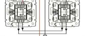
A multi-pole circuit breaker is indicated by several identical symbols, connected by two parallel lines on a conventional diagram or by slashes on a single-line diagram.
Two parallel lines indicate that switching (on/off) is performed simultaneously for all phases (poles). The number of oblique lines corresponds to the number of switched wires and poles of the machine.
And so on the body they indicate a thermal and electromagnetic release.
Selective connection of protective equipment
If a high load on the network is expected, the method of connecting several protection devices in series is used. For example, for a chain of four circuit breakers with a rated current of 10 A and one input device in the diagram, each circuit breaker with differential protection is graphically designated in series one after another with the device output to a common input device. What does this give in practice:
- compliance with the connection selectivity method;
- disconnecting only the emergency section of the circuit from the network;
- non-emergency lines continue to operate.
Thus, only one of the four devices is de-energized - the one that experienced a voltage overload or a short circuit. An important condition for selective operation: that the rated current of the consumer (lamp, household appliance, electrical device, equipment) be less than the rated current of the machine on the supply side. Thanks to the serial connection of protective equipment, it is possible to avoid fires in the wiring, complete blackout of the power system and melting of the wires.
Classification of devices
According to the drawn up diagram, electrical devices are selected. They must meet the technical requirements for a specific type of product. According to GOST R 50030.2-99, all automatic protective equipment is classified into several types according to the type of design, environment of use and maintenance. In this case, the unified standard refers to the use of GOST R 50030.2-99 in conjunction with IEC 60947-1. GOST is applicable for switching circuits with voltages up to 1000 V AC and 1500 V DC. Circuit breakers are classified into the following types:
- with built-in fuses;
- current-limiting;
- stationary, plug-in and retractable versions;
- air, vacuum, gas;
- in a plastic case, in a shell, open design;
- emergency switch;
- with locking;
- with current releases;
- serviced and unattended;
- with dependent and independent manual control;
- with dependent and independent control from the power source;
- switch with energy storage.
In addition, machines differ in the number of poles, type of current, number of phases and rated frequency. When choosing a specific type of electrical device, it is necessary to study the characteristics of the machine and check the compliance of the device with the electrical circuit diagram.
Marking on the device
Technical documentation obliges manufacturers of automatic devices to indicate full product markings on the housing. Basic symbols that must be present on the machine:
- brand – device manufacturer;
- name and series of the device;
- rated voltage and frequency;
- rated current value;
- rated differential current;
- UGO circuit breaker;
- rated differential short circuit current;
- contact marking designation;
- Operating temperature range;
- on/off position marking;
- the need for monthly testing;
- graphic designation of the RCD type.
The information indicated on the machine allows you to figure out whether the electrical device is suitable for the specific circuit indicated in the diagram. Based on the markings, drawings and calculation of power consumption, you can correctly organize the connection of the object to the power supply.
Circuit breaker designation on the diagram
Three pole circuit breaker
The conventional graphic designation of the machine in the diagram is determined by GOST 2.755-87 ESKD, alphanumeric - GOST 2.710-81 ESKD. There are no special requirements for marking, so electricians often use their own values and labels. You can find documentation where the definition of a switching device differs in different projects.
Each designer, when executing a circuit, can depict an RCD at his own discretion. It is enough to indicate the UGO (symbolic graphic symbols) and their interpretation in the explanations to the diagram.
Depending on the characteristics of the device, the elements have different letter symbols, as well as the following graphic symbols on the electrical diagrams.
It is recommended to position circuit breakers as, QF1, QF2, QF3. Switch disconnectors – QS1,QS2,QS3. Fuses in the diagrams are shown as FU with a serial number, where the coding of the letter Q stands for a switch or switch of power circuits, and F is a protective one. This combination is quite applicable not only to conventional machines, but can be a designation for a differential machine in the diagram.
For RCDs, the combination QSD is used; the designation of the differential circuit breaker in the diagram looks like QFD.
Symbol for ouzo in the diagram
No person, no matter how talented and savvy he may be, can learn to understand electrical drawings without first becoming familiar with the symbols that are used in electrical installation at almost every step. Experienced specialists claim that only an electrician who has thoroughly studied and mastered all the generally accepted designations used in project documentation can have a chance to become a true professional in their field.
Greetings to all friends on the website “Electrician in the House”. Today I would like to pay attention to one of the initial issues that all electricians face before installation - this is the design documentation of the facility.
Some compose it themselves, while others are provided by the customer. Among the multitude of this documentation, you can find copies in which there are differences between the symbols of certain elements. For example, in different projects the same switching device can be graphically displayed differently. Has this ever happened?
It is clear that it is impossible to discuss the designation of all elements within one article, so the topic of this lesson will be narrowed, and today we will discuss and consider how the designation of ouzo is carried out on the diagram .
Every novice master must carefully familiarize himself with generally accepted GOSTs and the rules for marking electrical elements and equipment on plan diagrams and drawings. Many users may disagree with me, arguing that why do I need to know GOST, I’m just installing sockets and switches in apartments. Design engineers and university professors should know the schemes.
I assure you this is not so. Any self-respecting specialist must not only understand and be able to read electrical diagrams, but also must know how various communication devices, protective devices, metering devices, sockets and switches are graphically displayed on the diagrams. In general, actively use project documentation in your daily work.
Designation of the machine on single-line diagrams
A circuit breaker is the main element of single-line diagrams in electrical engineering.
Currently, there are a lot of options for how designers show it on plans and diagrams, but not always correctly, which often leads to errors when assembling electrical panels or installing electrical wiring.
To prevent this from happening, you need to follow simple rules for displaying machines and marking them.
The graphical appearance of slot machines is standardized in:
GOST 2.755-87 ESKD “Conventional graphic symbols in electrical circuits. Switching and contact connection devices"
GOST R IEC 60617-DB-12M-2015 “Graphic symbols for diagrams”, which is identical to the international standard IEC 60617-DB-12M:2012 * “Graphic symbols for diagrams” ( IEC 60617-DB-12M:2012 “ Graphical symbols for diagrams ").
According to these standards, the symbol of the machine on a single-line diagram looks like this:
It is created from several graphic symbols of GOST, indicating certain features and functions of the device. A single-pole circuit breaker has three of them:
— Closing switching device
An example of a simple single-line diagram of an electrical panel consisting of just one such single-pole circuit breaker:
A two-, three- or four-pole machine is indicated by slashes placed on the incoming line, the number of which corresponds to the number of poles:
LETTER CODE
According to it, automata in diagrams are indicated by the symbols - QF:
Q - Switches and disconnectors in power circuits
F - Protective devices
The serial number of the machine is written after the letter code.
Uzo designation on a single-line diagram
The main groups of RCD designations (graphic and alphabetic) are used very often by electricians. The work of drawing up work diagrams, schedules and plans requires very great care and accuracy, since a single inaccurate indication or mark can lead to a serious error in further work and cause the failure of expensive equipment.
In addition, incorrect data can mislead third-party specialists hired for electrical installations and cause difficulties when installing electrical communications.
Currently, any ouzo designation on a diagram can be represented in two ways: graphic and alphabetic.
Which regulatory documents should be referred to?
Of the main documents for electrical diagrams that refer to the graphic and letter designation of switching devices, the following can be distinguished:
- – GOST 2.755-87 ESKD “Conventional graphic designations in electrical circuits of devices, switching and contact connections”;
- – GOST 2.710-81 ESKD “Alphanumeric designations in electrical circuits.”
Letter and graphic designation of machines on the diagram
One of the most common elements of electrical circuits are circuit breakers, or circuit breakers. They are installed, at a minimum, at the entrance to each electrical installation in production and near the electricity meter in an apartment or private house.
Modern apartment electrical panels usually have a single-line diagram with all the markings and designations. These drawings use different types of symbols:
- Letters, according to GOST 2.710-81;
- Graphic, according to GOST 2.755-87.
In addition, all equipment has serial numbers, the rated current and other parameters are also indicated there. Using these labels and connecting lines indicating wires and cables, experienced electricians can determine how an electrical installation works.
You need to start dancing “from the stove”, and reading the electrical diagram begins with the input circuit breaker. This is the main element of complex circuits of technological equipment, so it is important when designing to use the correct designation of the machine on the diagram.
Graphic designation of RCD on the diagram
So, above I presented the main documents according to which symbols in electrical circuits are regulated. What do these GOST standards give us for studying our question? I'm ashamed to admit, but absolutely nothing. The fact is that today these documents do not contain information on how the ouzo designation should be carried out on a single-line diagram.
The current GOST does not put forward any special requirements for the rules for drawing up and using graphic symbols for RCDs. That is why some electricians prefer to use their own sets of values and labels to mark certain components and devices, each of which may differ slightly from the values we are familiar with.
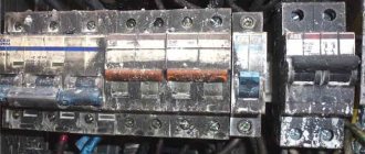
As an example, let's look at what designations are printed on the body of the devices themselves. Hager residual current device:
Or for example an RCD from Schneider Electric:
To avoid confusion, I suggest that you jointly develop a universal version of RCD designations that can be used as a guide in almost any working situation.
Designation of a difavtomat on a single-line diagram
In addition to conventional circuit breakers, differential circuit breakers, or RCBOs, are used in the circuits. There is no standard graphic or letter designation for these devices. It is not even in the most modern GOST R IEC 60617-DB-12M-2015.
Therefore, electrical equipment designers are guided by GOST 2.702-2011 and ESKD. These regulations allow you to independently create graphic symbols for devices that are not included in the current rules.
Guided by these norms, the symbol of the difavtomat, like the design of the device, is formed by merging two designations:
- RCD - a loop encircling the wires extending from the device:
- circuit breaker - the presence of a rectangle on the contact and a cross on the appropriate wire.
| Friends, I previously published a separate article on how RCDs are conventionally designated in diagrams. You can find it by following the link. |
In the single-line diagram, several oblique lines are drawn on the image of suitable cables. Their number corresponds to the number of conductors.
Important! A block of conventional graphic symbols of the UGO with decoding and explanations should be drawn on the electrical circuit.
Letter designation of ouzo on electrical diagrams
Any element on electrical circuits is assigned not only a graphic designation, but also an alphabetic designation indicating a position number. This standard is regulated by GOST 2.710-81 “Alphanumeric designations in electrical circuits” and is mandatory for application to all elements in electrical circuits.
So, for example, according to GOST 2.710-81, it is customary to designate circuit breakers using a special alphanumeric designation in this way: QF1, QF2, QF3, etc. Switches (disconnectors) are designated as QS1, QS2, QS3, etc. Fuses in the diagrams are designated as FU with the corresponding serial number.
Similarly, as with graphic symbols, GOST 2.710-81 does not contain specific data on how to carry out the alphanumeric designation of RCDs and differential circuit breakers on diagrams .
What to do in this case? In this case, many masters use two notation options.
The first option is to use the most convenient alphanumeric designation Q1 (for RCD) and QF1 (for RCBO), which indicate the functions of the switches and indicate the serial number of the device located in the circuit.
That is, the encoding of the letter Q means “switch or switch in power circuits,” which may well be applicable to the designation of an RCD.
The code combination QF stands for Q – “switch or switch in power circuits”, F – “protective”, which may well be applicable not only to conventional machines, but also to differential machines.
The second option is to use the alphanumeric combination Q1D for the RCD and the combination QF1D for the differential circuit breaker. According to Appendix 2 of Table 1 of GOST 2.710, the functional meaning of the letter D means “differentiating”.
I very often saw in real diagrams the following designation: QD1 - for residual current devices, QFD1 - for differential circuit breakers.
What conclusions can be drawn from the above?
| Due to the fact that there is no designation for RCDs and differential circuit breakers according to GOST, the information discussed in this article does not apply to mandatory regulatory documents, but is only a RECOMMENDATION. Each designer can depict these elements on the diagrams at his own discretion. To do this, you just need to provide conventional graphic designations (UGO) of the elements, their decoding and explanations for the diagram. All these actions are provided for in GOST 2.702-2011. |
How is ouzo indicated on a single-line diagram - an example of a real project
As the famous proverb says, “it’s better to see once than to hear a hundred times,” so let’s look at a real example.
Let's assume that we have a single-line diagram of the power supply of an apartment. Of all these graphic symbols, the following can be distinguished:
The input residual current device is located immediately after the meter. By the way, as you may have noticed, the letter designation of the RCD is QD. Another example of how ouzo is designated:
Please note that on the diagram, in addition to the UGO elements, their marking is also applied, that is: type of device by type of current (A, AC), rated current, differential leakage current, number of poles. Next we move on to UGO and marking of differential machines:
The socket lines in the diagram are connected through differential circuit breakers. Letter designation of the automatic machine on the diagram QFD1, QFD2, QFD3, etc.
Another example of how differential machines are designated on a single-line diagram of a store.
That's all, dear friends. This concludes our lesson today. I hope this article was useful to you and you found the answer to your question here. If you have any questions, ask them in the comments, I will be happy to answer. Let's share our experience, who designates RCDs and RCBOs in diagrams. I would be grateful for a repost on social networks))).
{SOURCE}
Letter designation of machines on the diagram
Simultaneously with the graphic designation, the letter designation of the machine is used on the electrical diagram . It consists of two letters of the English alphabet and is determined by GOST 2.710-81 and the Unified System of Design Documentation.
The letter code, as well as the graphic symbol, indicates the functions of the device:
- Q - switch or disconnector;
- F - protection device;
That is why in the diagrams the machines are designated QF . The letters are followed by the serial number of the circuit breaker.
Information! On single-line electrical diagrams drawn up in Soviet times, machines were designated by the letters “A” or “AB”.