Pass-through and cross-switch
A regular switch can only close or open an electrical circuit. But this is not enough to arrange lighting control from two or more different points.
For these purposes, pass-through switches are used, which are also called switches. With their help, they not only break the electrical circuit, but also switch current consumers from one line to another.
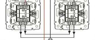
The design of the pass-through switch has two fixed contacts and one movable one, which connects its conductor with one of the contacts. You can understand the design and principle of operation of the switch from Figure 1. Pass-through switches always work in pairs.
Figure 1. Diagram explaining the operation of pass-through switches
This diagram perfectly illustrates the principle of operation of switches. They close the circuit only when both contacts are in the same position - they connect either the upper (in the diagram) or the lower conductor.
In order to turn off the light, just reconnect any of the switches. When the contacts are in different positions, the circuit will be broken. Turning on the light can also be done using any switch.
Thus, if pass-through switches are placed at different ends of the corridor, then you can control the lighting, regardless of what part of the room you are in.
The scheme under consideration works effectively, but from the point of view of saving wiring, it is not rational, since it is necessary to lay an additional two-core wire to connect the switch contacts. In a long corridor, such extravagance can be noticeable. Below I will provide you with a more economical, simpler circuit.
Cross switch
What if your room is located in the middle of a long corridor?
It turns out that such a possibility exists. To do this, you need to purchase a cross (reversing) switch. The principle of its operation is clear from the diagram in Figure 2. This device has not one, but two movable contacts that switch lines between pass-through switches. They are connected to each other.
Figure 2. Lighting control diagram from three places
By installing a crossover switch at the desired point, for example, at the door of your room, you can control the lighting from this third point. There is a scheme for turning on lighting from four or more points (Fig. 3).
This diagram is useful for arranging lighting:
- in long corridors from which there are entrances to individual rooms;
- on marching flights between floors;
- near cribs in children's bedrooms, which will allow children to independently turn on/off the lights;
- in private homes, for the convenience of controlling street lighting, etc.
Figure 3. Four-point lighting control diagram
Schematic diagram of contact groups of a cross switch
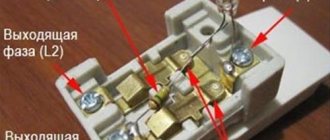
The base of a conventional single-key reversing switch includes 4 pairs of terminals. Each pair has its own visual designation, usually in the form of an arrow. This is necessary for correct connection of the device. Incoming arrows indicate a general (changeover) group of contacts, outgoing arrows indicate a permanent group.
Wires from the pass-through switch, which is the first in the circuit, are connected to the terminals of the general group. The terminals of the second group are intended for connecting wires going to the next pass-through device.
Installing sockets in the bathroom - do-it-yourself installation procedure and requirements for safety standards (120 photos + video)Smart GSM sockets: device, principle of operation and overview of the most modern devices. 150 photos of the best models
Location of sockets in the kitchen - planning the layout, rules and common mistakes when placing kitchen sockets. 135 photos of ideas for convenient placement
Reversible devices can be operated in two switching schemes:
- Direct (as in the case of 2 pass-through switches).
- Cross
The first case assumes a direct connection configuration with a circuit making and breaking function. In the second case, the device allows you to implement the inversion mode. This allows you to use the device not only as a switch for controlling lighting fixtures, but also as a universal switch. This makes it possible to expand the functions of electrical circuits and provides greater variability in installation.
Design
Cross switches (LeGrand, Schneider Electric and others) have not three contacts (like most standard control units), but four. This design allows you to simultaneously disconnect or enable two contacts. Thanks to this, several power lines (in this case, two) are simultaneously closed or, on the contrary, opened.
Photo - diagram of the operation of the cross switch
The main difference between pass-through switches and cross switches is that the former can be used independently, while the latter cannot. Cross models are used only in conjunction with pass-through models, but their designation on the diagrams is identical.
They are two paired single-key switches (sometimes single-key), the contacts of which are connected using special metal jumpers. The main convenience of this design is that, if necessary, you can make them yourself. This model has only one button, which is responsible for the operation of the contact system.
Photo - connection principle
There are two types of such switches based on the principle of operation:
- Keyboards;
- Rotary.
In rotary contacts, the contacts are closed using a rotary mechanism. They are slightly more expensive than regular ones, but have more diverse design options.
And two for installation options:
- Invoice (Unica Q, Lezard);
- Built-in (Legrad, ABB).
The external one is mounted on top of the wall. To install it, there is no need to break through the surface of the house and install an additional block in the wall. This is very convenient if you are planning a designer renovation or simply do not want to re-decorate the room. But such models are considered insufficiently convenient to use - they are subject to physical influences and the influence of an aggressive environment.
Photo - light control diagram from three places
Built-in ones are used for installation in walls. They are used for wiring in all types of buildings. To install them, you must first prepare a hole in the wall corresponding to the switch box.
Features of cross-type switches:
- To connect them, exclusively four-core wires are used. As a last resort, experts recommend using two two-core wires with good insulation, but such a solution is impractical;
- Such a switch can be one-key, two-key or three-key. But it is recommended to install it only if it is necessary to turn off the lights from three different places (say, at the beginning, middle and end of the corridor). In all other cases, you can use classic pass-through options;
- The intermediate switch is installed exclusively at the stage of wiring around the house or apartment. This is its main drawback. Due to the connection of several contact groups, connecting the system requires a large number of wires, which can create a certain fire hazard;
- Among the advantages of the design are high wear resistance. Considering that the contacts of crossover models are more likely to close than through-type or conventional ones, the jumpers are made of durable, corrosion-resistant metal, most often copper or alloy steel. Most options have additional protection against condensation, dust and moisture.
Photo - connecting a single-key cross switch
Installation
Let's look at how to connect a cross double switch from Legrand. First you will need to develop a connection plan and diagram, this will save on cables and additional elements. Also, before starting installation work, the walls are grooved.
Photo - MGU3
Step-by-step instructions on how to connect a paired and two pass-through switches to control several lamps from three places:
- At the first stage of work, the connection is made according to the standard scheme for controlling light with walk-through models. A neutral wire is pulled into the distribution box from the panel. From the splitter it is transferred to the lamp contacts;
- Next, the phase cable is pulled from the shield. But after installing it in the junction box, the working wire is routed not to the lamp, but to the switch contacts (in this case, this is one of the feedthroughs);
- A series connection of contacts is made through the distribution box. First, the phase is transferred to the crossover switch, which should be located between two pass-throughs, taking into account the minimum cost of wires, and then to the second pass-through;
- After this, a connection to the lamp is made from the common contact of the second pass-through switch. After completing the pulling, the distribution box is mounted on the wall. Just like switches, it can be installed on top of a wall or directly into a prepared hole.
Cross switch device.
The design of the cross switch is almost the same as that of a conventional two-key switch. It also has two contacts, the same mechanism for switching contacts, but differs in the way they are switched.
independent contact switching
and both contacts can be closed or open at the same time, or one contact can be closed and the other open.
In a cross switch, the switching of both contacts is dependent
and occurs simultaneously.
Design features
Cross-type switches are equipped with four instead of three contacts. This design of the device allows you to simultaneously close or open two contacts, affecting several power supply lines at once.
Users are often interested in what a crossover switch is and how it differs from a pass-through switch. The main difference between them is that intermediate type devices cannot operate independently and are only used in combination with pass-through devices. At the same time, they are designated similarly on electrical circuits. The design of the cross switch has the following elements:
- mechanism for wall mounting;
- contact group with control unit;
- output terminals;
- conductive jumpers located in the housing.
Like all types of switches, cross switches can have a surface-mounted or built-in design and can be used for open or hidden wiring. It should also be remembered that sometimes a combination of these methods is used. On sale you can find not only a one-key or two-key cross switch, but even a device with three buttons. Some devices are equipped with a rotary activation mechanism, but this does not change the principle of their operation.
Operating principle
Below is a diagram for connecting intermediate switches, providing independent switching on and off of lights from two different places.
Zero is connected directly to the lighting device, the phase is connected through a pair of switches connected by a two-wire conductor. With two switches PV1 and PV2, the first and third contacts close, as a result the circuit is closed, and electricity flows into the lamp.
To open the chain, press the button of any switch, for example, PV1. As a result, the first and second contacts will close. When you press the PV2 switch button, the same thing happens. Thus, we obtain a lighting system that is independently controlled from different points.
What is the difference between a pass-through switch and a switch
Sometimes novice electrical installers get confused in the terminology, diagrams and operating principles of these two, or rather three, mechanisms (since switches also come in two types ), not to mention ordinary buyers who are trying to install themselves or buy the necessary devices for further installation . In this article, we will try to shed some light on the difference between a switch and a switch.
So, switches and switches are used for switching electrical circuits for lighting and household appliances, they also look the same in appearance, the only difference is in the number of contacts on the back side. But a switch is designed to break one circuit, and a switch is designed to switch between circuits. A switch is used to control light from one place, switches are used to control light from two or more places, and “pass-through” switches are used to implement control from three or more places. Below we will look at the diagrams of how this works:
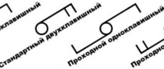
1. Single-key switch - switches the phase coming to it and going out to the lamp.
As we see in the diagram, the switch only needs two contacts, one for the incoming phase, the second for the outgoing phase.
2. Single-key switch - switches the phase with one of two circuits passing between the two switches.
This scheme is used, for example, in a corridor ; by installing one switch at the entrance to an apartment, we can turn on the light, and after walking along the corridor, by installing a switch at the end of the corridor, we can turn off the light. As can be seen from the diagram, one key switch must have three contacts, one for the incoming (or outgoing) phase, the second and third for the two circuits between the switches. It is important to note that switches are always used in pairs , and also that a switch can be installed instead of a switch and it will work like a switch, but the switch will not cope with the functions of the switch.
Lighting control scheme from two places
By connecting double pass-through switches, it is possible to control two light bulbs alternately from two places. This circuit contains a pair of two-key switches, which allows you to turn on one of the lamps at the entrance, while simultaneously turning off the other. When exiting a long corridor, for example, a second device allows the reverse operation. Thus, lighting control is carried out alternately from 2 places.
Important! In this case, the direction of movement along the corridor is not of fundamental importance.
It is possible to implement such a control algorithm only if there is a double pass-through switch. Systems organized in this way significantly simplify lighting control in the conditions described above.
Installation procedure
Before connecting pass-through two-key switches and illuminators, places for their installation are first selected (the first ones should be located at the very exit-entrance to the room). After this, they move on to the main work, carried out in the following sequence:
- First of all, at selected points, installation niches are drilled into the walls with a special crown, the diameter of which is selected to be 72 or 80 mm (depending on the device housing).
- Then special plastic boxes are fixed into them (they are called “socket boxes”).
- When laying the wiring externally, the housings of the switching products are mounted on the wall using self-tapping screws.
- Upon completion of the installation of two-key pass-through switches, proceed to the installation of two groups of illuminators, in each of which the lamps are switched on in parallel (this will eliminate the possibility of a complete blackout of the circuit if one of them burns out).
- Then, two phase wires and one neutral wire are laid from the installed chandeliers or lampshades to the distribution box.
Since the requirements of the PUE require grounding of any connecting wiring with loads, a cable with three cores is laid from the lamps.
Please note: It is recommended to choose the location for installing the distribution box (RC) in the middle of the room, which allows you to save on the length of the wires.
Since the design of the two-key pass-through switch has 6 contact terminals, two 3-core cables will need to be laid from it to the switch. When disconnecting system elements, the wires to the RC must be connected according to the diagram below.
We suggest watching a video on how to connect two-key pass-through switches without a junction box.
Attention! In this installation option, the socket boxes must be deep.
Scheme for connecting three or more switches
From the above diagram it is clear that pass-through switches can only be used in pairs - a third similar device cannot be connected in the same way. This problem is solved by using a so-called cross or reversing switch - outwardly it looks like a regular one, but unlike a pass-through switch, it has not two or three, but four terminals.
Its purpose is to swap the connected wires when switching. For example, if we number the terminals, then let the input terminals be 1 and 2, and the output terminals 3 and 4, respectively. The current through one wire can be supplied to terminal 1 and passing through the switch to terminal 3, and through the second it can enter terminal 2 and be output through terminal 4. After switching, the current is still supplied to terminal 1, but is output through terminal 4, and if it goes to terminal 2, it will be output through terminal 3. An unlimited number of such devices can be used in the circuit. The principle of their operation is shown in the figure:
Advantages of pass-through switches
Duplicate switches have a number of positive qualities that make them stand out among conventional devices.
Pros:
- Controlling one light source from different parts of the room.
- Safety of use.
- Easy to install and configure.
- Low cost and, as a result, low price.
- Saving electricity.
- Reliability in operation.
- Possibility of installation by yourself without the involvement of a specialist.
How to connect a two-key pass-through switch
Connecting a two-key pass-through switch essentially differs only in the number of keys and wires, the circuit remains the same. The switch circuit already has 6 wires. Four of them are outputs and two are inputs, two outputs each for the switch keys.
How to make a two-key pass-through switch
The neutral wire runs through the junction box to the lamps.
The phase wire is connected to the first switch (distributed to each key).
The two ends of the phase wire are connected to their pair of outputs of the first switch.
Sometimes it is necessary to make pass-through switches. What it is? This is when the light can be turned on in one place and turned off in another. Or vice versa.
Here are examples of real-life situations where you need to turn lights on and off from different places. I encountered some of them in practice, some I observed in different places.
- In a hotel, the light can be turned on at the entrance to the room, and turned off with a switch at the head of the room while already lying in bed.
- On the balcony, which has two exits (from the kitchen and the room). When you exit through one door, the light on the balcony turns on, and when you exit through another, it turns off.
- At the dacha you can place two switches: at the bottom of the stairs to the second floor, and at the top.
There are two main ways to implement such a scheme:
- using pass-through switches;
- using special relays.
A pass-through switch is a device with a changeover contact. Outwardly, it looks exactly like a regular one. The diagram on such switches looks like this.
The disadvantage of this scheme is that the position of the switch when the light is off is not very clear. The switch key can be in either an “up” or “down” position. That is, the position of the keys of both switches when the light is off is in antiphase.
The second drawback is that you cannot turn it on/off at three points. For example, in the bedroom I would like to have light on both sides of the bed and near the entrance. Then you need to use a special relay.
In my practice, I used the MR-41 relay manufactured by the Czech company Elko. It is quite expensive, about 1400 rubles. But it solves the problem completely.
The relay is installed in the electrical panel in the same way as a regular one. There are many buttons connected to it (apparently up to 80) without locking. And a lamp is connected to the power contacts of the relay.
Both Legrand and ABB have similar devices, but are much more expensive
When choosing such devices, it is important to ensure that two functions are available:
- ensuring that the backlight of the switch key is lit (not everyone does this);
- restoration of the current state after a power failure.
Elko implements both of these functions. Another problematic issue is the search for a switch without latching. I managed to find such switches in the popular Legrand Valena series. However, an attempt to order showed that you can buy such switches right away, without pre-ordering, even in Moscow, in only a few places.
Two-gang switch with backlight
In the simplest case, connecting a two-key Legrand switch is done according to the classical scheme. At the bottom of its body there is an input working contact to which the phase wire is connected. At the same time, two conductors “depart” from above it - each to its own illuminator or group of light bulbs.
Often these wires are laid to a distribution box, from where they are routed according to the required loads. In some cases, pre-formed groups of illuminators are used as such loads.
Features of connecting the backlight
The backlight, available in some Legrand models, is usually connected in parallel to an open contact, which causes it to glow after the lighting device is turned off. The only drawback of this inclusion is the not very pleasant blinking of energy-saving lamps, which occurs due to a small part of the voltage reaching them. This effect is not observed with incandescent lamps and their halogen analogues.
Legrand products use a semiconductor LED or neon bulb as lighting. Outwardly, they are practically the same, but they pass currents of different magnitudes through themselves. For LEDs they are about 2 mA, and for neon bulbs they are about 0.1 mA.
The procedure for removing the backlight bulb
To turn off the built-in backlight that interferes with users, you will need:
- Turn off the input circuit breaker on the apartment panel.
- Remove the housing and decorative cover of the switch and provide access to the LED (neon).
- Take a screwdriver and loosen the screw fastening of the wires connecting the light bulb to the two contacts of the switch.
- Remove it along with the limiting resistor.
After all these operations, the LED lighting fixture controlled by the switch will stop flashing in the off position.
Installation diagram of a control line from three or more places
A universal option - regulation of light sources from 3 points. Based on it, the number of switches can be increased to 10 or more. The creation of an electrical circuit is carried out by 3 elements: two pass-through devices and one cross-over device.
Pass-through devices are mounted at the ends of the switching line, a crossover device is installed in the area between these elements. When the first switch is turned on, the phase current flows through the base circuit and the lighting fixture lights up. When you press the cross switch key, the circuit opens. When turned on, current flows through the input wire. In this position, one of the contacts is constantly under phase. On the third switch, the procedure for closing and opening the circuit is similar to the first device.
If you want to control lighting from a large number of places between pass-through products, the required number of cross devices is installed.
This diagram assumes 7 connections in the junction box.
Since in any case there will be three circuits in the circuit, three single and cross switches are used. However, paired through and cross products (2 double and one single) are more often used. Pass-through products at the ends of lines can be replaced with three-key elements. The consumer independently decides which option is preferable for him.
Connections from multiple locations are common in high-rise buildings. Typically, one switch is designed to control the lighting of three floors. It is also becoming widespread in private households, where there are a lot of outdoor lights (garden paths, gazebos, gates, garages).
https://youtube.com/watch?v=9cG_VmdR4uk
Specifications
You can buy a crossover switch at any electrical store; the price depends on the model and manufacturer. Let's look at the characteristics of several well-known switches.
ABB Basic 55 white:
| Rated mains voltage, V | 220-250 |
| Maximum permissible current, A | 10 |
| frequency Hz | 50 |
| Contacts | Silver plated, resistant to moisture and steam |
| Frame | Thermoplastic |
| Price | From 10 USD e. |
Cross Schneider Electric SDN:
| Voltage, V | 250 |
| Current, A | 10 |
| Rated power, W | 2300 |
| Protection | IP20 |
| Cost, y. e. | From 3 |
Legrand Valena (its analogue Anam):
| Type | Single-key |
| Maximum voltage in AC mains, V | 230 |
| Current, A | 10 |
| Material | Polycarbonate |
| frequency Hz | 50–60 |
| Cost, y. e. | From 4 |
Viko Carmen (in terms of characteristics and price, Viko has a Chinese equivalent - Makel):
| Allowable voltage, V | 220–250 |
| Current, A | 10 |
| Material | Plastic |
| Design | Built-in two-key |
| Price | From 1.00 e. |
Lezard Nata:
| Mains voltage, V | 220 |
| Current, A | 10 |
| Type | Single-key overhead |
| frequency Hz | 50 |
| Material | Plastic |
| Price, y. e. | From 3 |
Cross disconnect principle
A crossover switch is similar to a regular single-key switch, the only difference being the presence of four terminals inside. The crossover is named because the two electrical lines it switches are connected into a cross.
The cross disconnector simultaneously disconnects the first and second switches, then connects them synchronously. This movement of the contacts causes the light to turn on and off.
Advice! Pay special attention to the correct connection of the ends of the electrical cables, otherwise the entire system will not work.
The number of points may vary, but the more there are, the more difficult the switching in the distribution box. It is necessary to clearly mark the wires when conducting them so as not to confuse them.
Connecting 2 types of switches
Connecting 2 types of switches
When connecting, it is important to do this according to the diagram. If installation errors occur, the system will not work correctly - it will not turn on, will not turn off, or only some switches will work.
The following picture shows the connection of a single-key switch with two contacts.
Connecting a two-pin single-key switch
This completes the connection of the pass-through switch.
Connecting a pass-through switch
Important! High voltage is life threatening. Therefore, all work must be carried out with the input machine turned off.
Design features
Cross-type switches are equipped with four instead of three contacts. This design of the device allows you to simultaneously close or open two contacts, affecting several power supply lines at once.
Users are often interested in what a crossover switch is and how it differs from a pass-through switch. The main difference between them is that intermediate type devices cannot operate independently and are only used in combination with pass-through devices. At the same time, they are designated similarly on electrical circuits. The design of the cross switch has the following elements:
- mechanism for wall mounting;
- contact group with control unit;
- output terminals;
- conductive jumpers located in the housing.
Like all types of switches, cross switches can have a surface-mounted or built-in design and can be used for open or hidden wiring. It should also be remembered that sometimes a combination of these methods is used. On sale you can find not only a one-key or two-key cross switch, but even a device with three buttons. Some devices are equipped with a rotary activation mechanism, but this does not change the principle of their operation.
How to avoid 5 installation mistakes
There are mistakes that inexperienced electricians make when laying and connecting wires:
- The neutral wire is connected to the first switch. Before connecting, you should use a tester to find the phase wire.
- Instead of a pass-through switch, an intermediate switch with two changeover contacts and jumpers is installed. This is a valid option, but such devices are more expensive.
- Use instead of special conventional switches. This scheme will not work. You need to take the necessary devices.
- Incorrect wire connection. Before starting work, draw a connection diagram and mark the wires.
- Strip the ends of wires that are not long enough. Such ends do not hold well and fall out of the terminal. They should be stripped to a length of 8mm.
Connection diagram for a pass-through switch with 2 places
The circuit of a pass-through switch from two places is carried out using two pass-through single-key devices that work only in pairs. Each of them has one contact at the entry point, and a pair at the exit point.
Before connecting the pass-through switch, the connection diagram clearly displays all the stages; you should de-energize the room using the appropriate switch located in the control panel. After which it is necessary to additionally check that there is no voltage in all wires of the switch. To do this, use a special screwdriver.
To complete the work you will need: flat-head, Phillips and indicator screwdrivers, a knife, side cutters, a level, a tape measure and a hammer drill. To install switches and lay wires in the walls of the room, appropriate holes and grooves must be made in accordance with the device layout plan.
Unlike conventional switches, pass-through switches have not two, but three contacts and can switch the “phase” from the first contact to the second or third
Wires must be laid at a distance of at least 15 cm from the ceiling. They can be placed not only in a hidden way, but also placed in trays or boxes. This installation makes it possible to quickly carry out repair work in case of cable damage. The ends of the wires must be inserted into installation boxes, in which all connections are also made using contactors.
Procedure for installing pass-through switches at 2 points: connection diagram
All actions for installing switching devices are carried out on the basis of a connection diagram of 2 places of pass-through switches, which can be found on the Internet. It differs from the installation of conventional switches, since there are three wires instead of the usual two. In this case, two wires are used as a jumper between two switches located in different places in the room, and the third is used to supply the phase.
Any type of lamp can be used as a lighting source in such a scheme - from conventional incandescent lamps to fluorescent, energy-saving and LED
Five wires must be suitable for the distribution box: power supply from the machine, three cables going to the switches, and a connected wire directed to the lighting fixture. When constructing a connection diagram for a single-key pass-through switch, three-core cables are used. The “zero” and grounding wires are led directly to the light source. The brown phase wire, which supplies current, passes through the switches, according to the diagram, and is output to the lighting lamp.
The switches are connected at the break in the phase wire, and the zero, having passed through the distribution box, is directed to the lighting fixture. Passing a phase through the switch will ensure safety during repair and maintenance of the lamp.
Installation of a pass-through switch consists of the following sequence of actions:
- the ends of the wires are stripped of insulation;
- using an indicator it is necessary to determine the phase wire;
- using twisting, the phase wire should be connected to one of the wires on the first switch (white or red wires are used here);
- the zero terminals of the switches are connected by wires;
- connecting a separate wire of the second switch to the lamp;
- in the junction box the wire from the lamp is connected to the neutral wire;
When installing pass-through switches yourself, you need to take care of safety precautions
What limits the number of pass-through switches
A chain of switches that allows switching electric current from several points should not be too cumbersome. The contacts resist electric current. It is small, but over a long chain of contacts the current can decrease noticeably.
With a large number of switches connected one after another, the reliability of the circuit decreases and failures are possible. Therefore, we rarely see a string of pass-through and crossover switches of ten or more pieces. Most often this is a pair of switches, somewhat less often - a chain of three, four, five.
Three-point light switching diagram
The previous section discussed turning electricity on and off from two points: the circuit is very simple.
Well, what if you need to turn the light on and off from three points? This problem arises when trying to save light in a multi-story building and at the same time avoid walking up the stairs in the dark. There is nothing complicated about this. But you will need an additional switch, and not a pass-through switch, but a cross switch.
Rice. 3 Cross switch circuit
Using a crossover switch, phase can be transferred from any input to any output, and the circuit between any input-output pair can be interrupted. Using a cross switch and two pass-through switches, you can assemble a light on/off circuit from those points, for example, on a staircase in a three-story building:
Fig. 4 Light on/off diagram from three points
Figure 4 shows the position of the switches at which the light is on. By clicking a key on any of those switches, we turn off the light. After this, press a key on any switch and the light will turn on.
What if there are not three floors, but five or six? You can assemble a circuit so that the light will turn on and off from any floor.
You always need only two pass-through switches: at the beginning and the end of the chain. Cross switches are placed between them. An example diagram for a four-story staircase is shown in Fig. 5.
Rice. 5. Four-point light on/off circuit
Armed with a pencil and paper, you can draw different options and make sure that pressing any key on any switch leads to a change in the situation: the light that was on goes out, and if the light was turned off, it lights up.
This wonderful circuit can grow by adding more crossover switches.
No matter how many crossover switches there are with four contacts, there should only be two pass-through switches: at the beginning and at the end.
How to properly dismantle a socket
So, having examined the main technical characteristics of sockets and their types, you can proceed to the main thing, how to remove the socket from the wall. To do this you should need:
- small screwdriver with plastic handle,
- insulating tape,
- latex gloves,
- tester.
Here are the step-by-step instructions:
- The first step is to turn off the power to the apartment. In this case, you should check several times that the electrics are actually de-energized. You can use a tester for this.
- Depending on the type of outlet, the decorative cover is removed. It can be secured with screws or latches. Domestic sockets use a screw.
- Then the socket fastenings are unscrewed. If the legs are movable, then when the screw is unscrewed, it will become accessible for removal.
- Carefully pull out the entire socket structure and see how it is secured
If you want the wallpaper to look beautiful on the wall, then before pasting the surface, remove all sockets and switches from it. No amount of precision will help you get around the fixtures without removing them - the wallpaper around the perimeter will be uneven, and after the repair there will be a bitter aftertaste.
Below is a brief instruction with a photo; after spending 5 minutes on it, you will not receive an electric shock, and the wallpaper will look beautiful in the interior of your apartment.
What is a pass-through switch and how does it work?
It would be more correct to call this device a switch - it is a switch for users rather out of habit, since it is used to turn lighting on and off. If you call it correctly, then it is much easier to understand how it differs from standard switches - this name most fully reflects the essence of its effect on a working electrical circuit.
Like a standard switch, a walk-through switch has only two positions, but the fundamental difference is that in a conventional device it is strictly defined, for example, up is on, and down is off, but with a walk-through, these sides are constantly changing.
The operating principle of the pass-through switch becomes clearest when comparing the electrical circuits between it and the standard device, which is shown in the figure:
If a regular one in an open state simply breaks the circuit, then in the case of a pass-through one it all depends on the position of two switches at once:
From the diagram it is clear that each of the switches must have three terminals - one for the phase that comes from the power source and two for the “control” wires. When either of the two switches changes position, the circuit either closes or opens, depending on what state it was in before.
Read also: Hexagon cone bolt
Additionally, we can formulate one more difference between a switch and a switch - the latter can always be connected as a simple switch, but doing the opposite will not work.
Lighting control from three places or more
There are times when it becomes necessary to turn on the light in a room not from one or two places, but from three, four or more. To implement such a scheme, manufacturers manufacture intermediate switches (switches). An example of a control scheme from three places is shown in Figure 7.
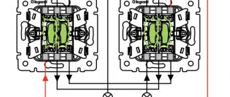
Figure 7. Schematic diagram of connecting two-pole two-key through and intermediate switches
As can be seen from the diagram, the intermediate switch has four fixed and two moving contacts. When a key is pressed, the moving contacts simultaneously switch from one pair of fixed contacts to another pair.
Figure 8. Wiring diagram for connecting single-pole single-key pass-through switches and intermediate switch
In order to be able to turn the light on and off, for example, from four places, another intermediate switch is installed. It is placed between one of the pass-through switches and the existing intermediate switch. By analogy, you can increase the number of control positions to any value.
Figure 9. Schematic diagram of lighting control from five places
Legrand Valena cross switch connection diagram
Legrand switches connection diagrams
In this section of the site, you will find various connection diagrams for Legrand Valena mechanisms. Visual connection diagrams for universal (pass-through, corridor, intermediate) switches, illuminated switches, and diagrams of various interactions will always be useful to both experienced electricians and the average installer.
Connections of “through” and “cross” switches are very simple, unless, of course, the “electrician” knows what “zero” and “phase” are.
CONNECTION DIAGRAM FOR LAY-OUT SWITCH FOR TWO CONTROL POINTS:
CONNECTION DIAGRAM FOR PASS-THROUGH SWITCH FOR THREE CONTROL POINTS:
An additional "crossover" switch is used.
CONNECTION DIAGRAM FOR A LAY-OUT SWITCH FOR FOUR OR MORE CONTROL POINTS:
This scheme differs from the previous one only in the number of control points.
Everything is very simple. You will have to run an additional cable between the switches.
CONNECTION DIAGRAMS FOR LEGRAND SWITCHES
Switch 774301 (774401)
Illuminated switch 774310 (774410)
Double pole switch 774302 (774402)
Double switch 774305 (774405)
Control from 2 places (switch for 2 directions 774306 (774406))
Control from 2 places (2-way switch with backlight 774326 (774426))
Control from 2 places (2-way switch with indication 774325 (774425))
Control from 2 places of two groups of lamps (double switch for 2 directions 774308 (774408))
Control from three places (2 switches for 2 directions and an intermediate switch 7743 06+7743 07+7743 06 (7744 06+7744 07+7744 06))
Switch for controlling blinds 7743 04 (7744 04)
Push-button switch for controlling blinds 7743 14 (7744 14)
Source
Top 5 manufacturers
NESSEN switch
Equipment produced by any company differs in price, quality and range. But there are manufacturers whose products are especially popular:
- Cross switches from the Turkish company Vico. Connecting these devices is similar to connecting devices from other factories. The products of this company are distinguished by their quality and affordable price. All parts are made from high-quality materials and are controlled at all stages of production.
- German company Gira. The products are of high quality and wide range.
- Cross switches from the French company Schneider Electric (“Schneider Electric”). The Schneider cross-switch circuit is similar to equipment circuits from other companies.
- Cross switches from the Swedish-Swiss company ABB (Asea Brown Boveri Ltd). The company produces equipment for electrical engineering and power engineering. The connection diagram for the ABB crossover switch does not differ from the connection diagrams for equipment from other companies.
- Switches from the French company Legrand are distinguished by their wide range and reliability. You can note the two-key (double) cross switch Legrand Valena and Legrand Ethics. The connection and diagram of the Legrand double crossover switch are similar to the connection and diagram of devices from other manufacturers.
The following figure shows the assembly of Legrand Valena, a two-key crossover switch.
Legrand Valena assembly
Information! Equipment manufactured by any company is installed and connected in a similar way.
Pass-through type switch design
Externally, a main switch is no different from a regular switch, except for the presence on the key of a conventional image in the form of two triangles and a diagram of the device on the back side of the dielectric base.
Inside the pass-through switch there are three contacts: two fixed and one movable (changeover), driven by the external key of the device. The changeover contact has two possible operating positions - on one of the fixed terminals. By pressing a key, the movable contact moves from one terminal to another, breaking one circuit and closing the second.
This design feature of the pass-through switch is the basis for a network design in which one lighting fixture can be controlled from two different locations. The neutral and grounding wires from the distribution box are connected to the lighting device, and a break is made in the phase conductor with two pass-through switches, between which two alternative lines are laid.