What types of switches are there with on indication?
Illuminated Triple Switch
Illumination in electrical switches is a neon bulb or LED. Visually it is almost impossible to distinguish them; the only difference is that neon lamps consume less electricity, but create a larger voltage drop. The minimum current for LEDs to glow is 2 mA, the voltage drop is 2 V, and for neon varieties these figures are 0.1 mA and 70 V, respectively. This is important to consider when choosing an electrical switch.
Switches with an indicator may not work correctly with different types of lamps. The design works smoothly and efficiently with halogen and incandescent lamps. It is better to refuse to use LED and energy-saving ones or take special measures. The most common malfunctions are the light blinking in the off position of the switch, the indicator in the switch does not light up.
The backlight can be equipped on all types of switches and with any number of keys. The location of the glowing indicator can be different: at the top or in the middle of the key, in the center or at the bottom of the device body itself.
Illuminated switch device
Illuminated switch design
Connecting a switch equipped with an indicator light is usually not difficult. It is enough to choose a high-quality model or upgrade an already purchased one.
The backlight in the device consists of neon lamps or LEDs connected in series with each other with resistance. This small circuit is connected in parallel with the switch contact. The circuit is always energized, regardless of whether the light is on or off.
If the switch is turned on, the backlight color is closed by a contact that is characterized by lower voltage. There is practically no current flowing through the backlight, therefore it does not light up.
A current-limiting resistor is connected in series with the neon lamp or LED in the switch. It is installed in order to reduce the current to optimal parameters. LEDs and neon lamps require different amounts of current, so the resistors are set to different values.
- For neon bulbs - 0.5-1 MΩ, power dissipation - 0.25 W.
- For LEDs - 100-150 kOhm, minimum power dissipation - 1 W.
Connecting directly through a resistor is not the best option. This is due to the performance of the circuit, as well as the tendency of the resistor to overheat. It is also possible that reverse current will flow through the electrical circuit. This will inevitably lead to breakdown of the LED.
With diode
Backlight circuit with a diode and a neon lamp
The first step is to solve the problem of reverse current flow. It's easy to fix - you need to install a diode parallel to the LED element.
If you connect the device according to a given circuit, the power dissipation of the resistor will not exceed 1 W, the resistance will fluctuate between 100-150 kOhm.
It is important to choose the right diode, whose technical characteristics will be similar to those of an LED light bulb.
This scheme, despite its ease of implementation and performance, has a drawback - the backlight consumes a considerable amount of electricity, and the resistor heats up.
A backlit switch of this type is compatible and will work correctly with incandescent lamps. If we talk about economical types and LED chandeliers, then the work will be intermittent.
To save energy with a capacitor
Backlight circuit using an LED and a capacitor
To eliminate the problem of resistor overheating, as well as to reduce the amount of energy consumed, the circuit is additionally equipped with a capacitor. The parameters of the resistor also undergo changes, since its task is to limit the charge of the capacitor.
The resistor value will fluctuate between 100-500 AM, and the capacitor parameters will be 1 mF, 300 V. The resistor values are established experimentally.
The advantage of this scheme is that it consumes virtually no electricity. Monthly consumption is about 50 W. However, placing a capacitor in a very limited space is quite problematic. Also, the circuit does not guarantee uninterrupted operation with energy-saving and LED lamps.
Electrician in the house
Author: admin, March 12, 2013
LED backlight of the switch.
LED light switch
How to make your own LED backlight for a switch , how to make a neon backlight for a switch , which parts are best to use, we will look at in this article, as well as the types of electrical circuits for backlighting a switch, their advantages and disadvantages.
So, from an ordinary standard switch we make a backlit switch; for this we assemble a simple circuit and install it in your switch. In this case, it is not necessary to drill a hole for the LED; its glow will be visible through the switch key, especially in the dark.
The diagram shows:
L1 - incandescent lamp, S1 - switch, R1 - MLT-0.25 130 kOhm resistor, or any other with a dissipation power of at least 0.25 W or a similar value, D1 - AL307BM LED, or any other small-sized one, the brightness of the glow will depend from the nominal value of R1, D2 - diode KD522B, or any other small-sized one, with an allowable reverse voltage of at least 30V.
The principle of operation of the circuit.
When the switch contacts are open, current flows through the limiting resistor R1, LED D1 and the filament of the incandescent lamp L1, the current is very small, so the filament of the lamp does not heat up, and the resistance of the cold filament is almost zero. Only the LED is lit, diode D2 serves to protect LED D1 from breakdown by the reverse half-wave voltage, since the permissible reverse voltage of the LED is a few volts. The circuit without diode D2 will also work, but not for long.
When the light is turned on, the S1 contacts close and the entire circuit is simply short-circuited by the switch contacts and the LED does not light up.
This circuit is designed to work with any incandescent lamps; when using some (usually cheap) energy-saving lamps, periodic dim flashing of the lamps or a faint glow may be observed. Also, flashing can be observed if zero is applied to the switch, and not phase.
The circuit consumes 1-2 W/hour. In order to save a little energy, you can use a capacitor instead of a quenching resistor; in this case, the circuit will consume 0.5-1 W/hour, but there will be an inconvenience: an additional part is a capacitor, which may not fit into the switch.
Illumination circuit for a switch with a capacitor.
LED backlight with capacitor
The diagram indicates:
L1 - incandescent lamp, S1 - switch, C1 - capacitor 1 uF 400 V, R1 - resistor MLT-0.25 100 Ohm, D2 - diode KD522B.
The difference in the circuit is in the capacitor C1 and in the value of the resistor R1, which now serves to limit the charging current of the capacitor.
Neon light switch.
Neon light switch
You can also use a miniature neon bulb instead of an LED; it consumes very little electricity, but burns quite brightly.
The diagram indicates:
L1 - lamp, S1 - switch, R1 - resistor MLT-0.25 180 kOhm, L2 - neon lamp MH3.
This scheme is most preferable, since it can be used with any type of lamps, including energy-saving ones. The neon light bulb can be taken from a regular starter for 220V fluorescent lamps; there is a capacitor in the starter parallel to the light bulb, it needs to be unsoldered, we don’t need it. In this case, it is better to take resistor R1 at 500 kOhm.
It is best to not just twist the circuit parts together, but solder them with a soldering iron.
ATTENTION! When installing the circuit into a switch, it must be de-energized ! Be sure to check the absence of voltage using an indicator screwdriver, as written here. Don't forget about your safety.
It will be interesting to read:
How to connect copper and aluminum wires
Electrical wiring in a residential area
Automatic plant watering machine
Headings: Electronic devices, Electrical circuits Tags: electricity, electronics, electrical circuit
How to connect an illuminated switch
Operating principle of the switch
The operating principle of the device is based on Ohm's laws. Electric current flows along the path of least resistance when lines of different resistances are connected in parallel.
The connection circuit has the same high resistance regardless of the type of indicator used - neon bulb or LED. This indicator is provided by a limiting resistor.
When the switch is opened, the lamp serves as an ordinary conductor. A current flows through it with a small force, which is enough for the uninterrupted operation of the backlight.
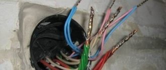
Where to put the wires
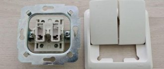
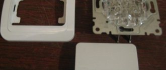
Before you begin installing a switch with an indicator, it is important to understand the design. To do this, it is recommended to remove the keys. Most often they are fixed to the body using pins or a latch.
Under the keys you can see terminals for connecting wires. They almost always visually appear as small copper pads with screws.
To connect the wires, their end must be removed from the insulating layer and the wire must be stripped, passed under the screw and contact plate, and secured securely using the first. You should tighten it with force, but the main thing is not to overdo it, the structure is quite fragile. After a while, it is better to check the quality of the connection again and tighten it again, since the copper gives in slightly under the screw.
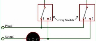
Connecting a light switch with one backlit key
Scheme for connecting the backlight to the network
The connection diagram is extremely simple - zero is supplied directly from the panel to the lamp, and a phase is connected to one of the switch terminals. From the second terminal the wire is fed to the output of the lighting fixture.
Implementing this scheme is simple and quick. The number of terminals depends on the number of keys in the switch. The single design has only 2 terminals, and the socket box must be equipped with two wires. It is simply impossible to get confused. You need to run one wire under the terminal from the panel, and the second from the lighting fixture. Where and what does not matter.
How to connect a switch with two keys and backlight
Connection diagram for a double model with backlight
The connection diagram for this electrical structure is not much different from the previous one. A three-wire wire is brought out into the socket box. Two wires are intended for a group of lighting devices, and one for power supply. This is where all the differences end.
In implementation, the method is a little more complicated, since you need to find a phase conductor and connect it to the required socket. The double switch is equipped with three contacts for connection. The phase is most often displayed in brown or red, and the color of the wires from the lighting device may be the same. Before connecting, the presence of phase voltage is checked, and if necessary, the wire is marked.
Illuminated switch and everything connected with it
If searching for a switch every day in a dark room takes a lot of time and nerves, and moving it to a more convenient place is not possible, then the problem can be solved with the help of backlighting, which will accurately indicate the location of the light switch keys. In practice, this is realized by adding an LED to an existing switch with your own hands or by replacing it with a similar illuminated switch with a built-in neon bulb.
Scheme and principle of operation of backlight using LED
The connection diagram for a switch with LED backlight is shown in Fig. 1. The principle of its operation is based on Ohm's law and is quite simple. At the moment when the contacts of switch Q1 are open, the load current flows through the circuit L – R1 – LED – HL – N.
The load current does not exceed the operating current through the LED, that is, 10 mA. Naturally, this current is not enough to light the main lighting lamp. For comparison, a 60 W incandescent lamp consumes 270 mA. In addition, the main part of the 220V network voltage drops not at the lamp, but at the resistor.
As a result, only the LED lights up, and its brightness depends on the resistance of resistor R1. As soon as the light is turned on in the room, the resistance of the switch contacts located parallel to the LED with the resistor will become close to zero. The current flow circuit will close through L – Q1 – HL – N.
The load current will follow the path with the least resistance and the LED will go out.
By the way, if you unscrew the lamp from the lamp or it burns out, the backlight will stop working.
Calculating the backlight on an LED comes down to choosing the right resistor R1. The fact is that 99% of the mains voltage drops across it, which means the power dissipation is quite high.
For example, given an LED current of 8 mA, let’s calculate the parameters of the resistor: A resistor that dissipates power of almost 2 W will be large in size and heat up so much that it can deform it upon contact with the plastic case.
Because of this drawback, the considered option has not found practical application.
In order to reduce heat losses and protect the LED from breakdown, the switch illumination circuit is supplemented with a rectifier diode (usually 1N4007) connected in series with the LED (Fig. 2). In this case, not an alternating voltage of 220V is applied to the circuit elements, but a constant voltage - 0.45 times less, that is, approximately 100V.
The resistor value can be set in the range of 12-50 kOhm and experimentally select an option in which the brightness of the illuminating LED and the temperature of the resistor surface will be optimal.
The advantages of DIY LED lighting include the ability to independently choose the color of the LED, its size and installation location.
Illumination using a neon lamp
The circuit and principle of operation of a backlit switch with a neon lamp is completely identical to that with an LED, but has improved performance.
The main advantage of a neon light bulb is its extremely low current consumption, which does not exceed 1 mA, and ideally should be 0.1-0.2 mA.
This allows you to install a limiting resistor of much lower power and size, namely: It turns out that a miniature resistor with a power of 0.125 W easily fits under the case and does not heat up at all.
Compared to an LED circuit, this option is more economical, reliable and safe. And the service life of a neon lamp reaches 80 thousand hours. That is why backlit switches that use a neon lamp have found wider practical application.
Connecting a single-key switch with backlight
To assemble and then connect the backlit switch to a 220V network, you will need a little time and following the steps below in the instructions.
- It is necessary to de-energize the room in which the modernization and installation of a backlit switch will be carried out.
- Remove the light on/off switch by carefully prying it off from the sides with a screwdriver.
- Remove the switch from the wall and disconnect the wires.
- Depending on the shape and size of the housing, determine the installation location of the LED.
- Drill a hole with a diameter of 5 mm in the marked location.
- Solder a resistor to one of the LED terminals, and a diode to the second, observing the polarity.
- To avoid a short circuit, hide most of the leads together with the resistor under a heat-shrinkable tube, leaving the edges bare for connection to the terminals.
- If necessary, extend the assembled structure with wires.
- Use superglue to secure the LED in the hole.
- Clamp one of the backlight wires together with the “phase” into the switch terminal.
- Connect the other backlight wire, together with the wire going to the lamp, to the second terminal of the switch.
- Install the finished switch with LED in the reverse order.
If you plan to use a finished product, then points 4 to 9 are skipped.
Connecting a two-key switch with backlight
In 90% of cases, the design of a two-key backlit switch is no different from its single-key counterpart. The only exceptions may be exclusive models from foreign manufacturers.
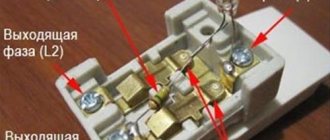
Basically, inside the switches with two lighting control keys there is one neon light bulb with a resistor, as shown in the photo. It’s easy to guess that the backlight will light up and go out only when you press one of the keys.
However, switch manufacturers do not see the need to install a second neon light, since one indicator light is sufficient for illumination in the dark.
The sequence of actions for assembling the backlight of a two-key switch is the same as for single-key models.
We only note that the electrician, at the moment of connecting the wires, has the right to choose which key the neon light will go off when pressing.
If we are talking about assembling the LED backlight with your own hands, then if you wish, you can install 2 LEDs - on each of the keys separately.
How to turn off the LED in a switch
All steps to dismantle a neon or LED lamp come down to the technology of replacing a conventional switch. The algorithm of actions is as follows:
- Completely de-energize the apartment or house, check the output voltage.
- Remove the decorative keys using a flat-head screwdriver or prying them with your fingers on both sides.
- The mounting bolts are unscrewed and the structure is removed from the mounting box.
- Using an indicator screwdriver, the contacts of the cores are rechecked for the absence of voltage.
- When the connection diagram has been memorized, the wires are disconnected.
Illuminated switch diagram
Redesigned circuit
The disassembled design of the switch is carefully examined. It is equipped with latches that connect the two parts of the case. Once they are open, the switch will separate. One part will be equipped with a resistor with an indicator light. The wires of the radio components are carefully cut from the backlight terminal and removed. The switch is assembled and installed in the reverse order.
Scheme for connecting an LED to a 220 switch in an apartment
Some people need instructions so that when the device burns out, they can find out what they did wrong.
Making a switch backlight with an LED yourself is not difficult at all. An extremely simple circuit can be assembled literally “on the knee” within a few minutes. But, if you don’t want everything to end with fireworks and burnt wiring, read this article carefully.
Scheme for connecting an LED to a switch in an apartment
Diagram and appearance of the switch
As you can see, the device consists of only two elements - a current-limiting resistor and a light source.
Many people who are not related to radio electronics may be confused by this scheme. After all, we put the LED in a 220V AC switch, although the LED itself is designed for a voltage of 2-12V DC. And the main lamp, in theory, should also glow with this connection.
How and why does it work?
Let's remember the school physics course:
- Voltage is the potential difference at the two ends of a conductor . The higher the voltage, the faster electrons travel through the wires.
- Current strength is the density of electrons in a conductor . When an electrical circuit encounters a section with high resistance along the path of electrons, some of them give up their energy to this section.
When the current (electron flux density) is significantly greater than the area can handle, the excess energy is converted into heat.
If there were no resistor in front of the diode, the current passing through it would be many times greater than its rated parameters, turning the diode crystal into a cloud. In this circuit, the resistor acts as a valve, cutting off most of the current.
Current will also flow through the incandescent lamp itself, but its strength is so small that the coil will not heat up.
Calculation of circuit parameters
Selecting a resistor for the LED. In this formula, the network voltage is taken as 320V, since it is necessary to take into account not the nominal parameter, but the effective peak voltage.
Selecting a resistor
How to make a backlight for a switch
The main purpose of an LED backlit switch circuit is to limit the amount of current flowing through the LED. For a diode, it doesn’t matter at what speed electrons pass through it, it will take its “portion” and convert it into a glow. If the electron flux density is higher than its throughput, the excess will be released in the form of heat, melting the crystal.
Installing an LED in a 220V switch, diagram:
Options for how to connect an LED
Option 1
This connection method will work, but for a very short time, a few milliseconds, until the filament of the incandescent lamp lights up. With this connection, the circuit current will be calculated based on the needs of the lamp, exceeding the needs of the LED by hundreds of times. This is the wrong option.
Option 2
This is already a viable option. Current-limiting resistor R1 will reduce the current to the required value. For a regular 20 mA LED, the resistor value should be:
(320V-3V)/0.02A≈16 kOhm and power 0.25-0.5W.
To increase the service life of the backlight and reduce the heating of the resistor, it is better to increase the resistance parameters by 3-4 times. Such a circuit can be seen if you disassemble a cheap Chinese switch with an LED. There is no reverse current protection, which does not contribute to the long life of such a device.
Option 3
Turning on the diode with reverse polarity protects the LED from reverse half-wave. This is important if there are powerful devices on the network line: washing machine, boiler, electric kettle. You can use any small-sized diode with a voltage of up to 500-1000 volts.
How to get rid of “blinking” lamps and possible problems
Installing a resistor in the socket
The main problem that owners of switches with indicators face is the flickering of the lamps and the indicator itself. Most of all, this phenomenon causes discomfort in bedrooms and the office. Improper operation will negatively affect the operating life of the switch itself and the lamp. You can get rid of the problem in the following ways:
- Give preference to LED lamps that are compatible with indicators in switches. Such lighting devices are already equipped with a soft start and a resistor. The device connects within a few seconds, so there is no flickering when the capacitor discharges. The main disadvantage is the high cost of such lamps.
- Connecting a shunt resistor in parallel will help get rid of the problem. It has no direct effect on the operating mode, but a small current will still flow through the resistor. Its power should be 2 W, and its resistance should be 50 kOhm.
- You can also connect an ordinary incandescent lamp with an energy-saving variety. In this case, the current flowing through the indicator circuit will pass through the filament. The disadvantage of this method is the large amount of electricity consumed.
- Incorrect operation may be caused by incorrect installation. For example, a mistake may result in the switch cutting off zero and not phase. This can cause not only incorrect operation, but also a short circuit. To solve the problem, just connect the switch correctly or call electricians.
The simplest, but not the most convenient way to get rid of the problem is to remove the backlight from the switch or install a regular modification that is not equipped with light bulbs.
Ways to get rid of “blinking” lamps
Everyone loves backlit switches - beautiful, convenient, inexpensive, practical. But they are ideally compatible only with incandescent lamps - conventional or halogen. It’s generally better not to use them with housekeepers - they blink constantly. Can work with high-quality dimmable LEDs. But only high quality ones. Read - dear. And then, over time, if there is a low-quality transformer somewhere, problems may begin. This means that either the lamps will shine at full intensity, or they will “burn out” when turned off. So, connecting an illuminated switch is only possible with “old” lamps?
Convenient - no need to look on the wall
There is a solution to the problem, and even several. Varying degrees of difficulty. Moreover, not all of them work and do not always work. So you can try them one by one. Here's how to make friends with an illuminated switch and LED bulbs:
- Screw one incandescent lamp into a chandelier with LED or housekeepers. The power is selected experimentally.
- If the LEDs are “built-in” and there is no way to add an incandescent lamp without damaging the chandelier, a capacitor with a capacity of 0.22 μF, rated at 630 V, is installed parallel to the chandelier. The same solution is suitable for groups of built-in LED lamps. A capacitor is placed in front of the first lamp in the branch, parallel to it.
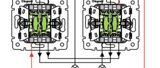
- The radical solution to the problem is to “bite out” the backlight circuit. This will not affect the functionality of the switch in any way. The second way is to pull out the neon lamp. This is easier if the circuit is integrated into the body, as is done in Legrand illuminated switches.
Just remove the highlight
All options except the last one have one drawback. Due to stray currents that flow through the backlight circuit, LED lamps are constantly energized. As long as the current is insufficient to start glowing, this is simply not noticeable. But the built-in voltage converters are “in operation” all the time. How this affects the lamps is not yet very clear, but there is an assumption that they will burn out faster.
If searching for a switch every day in a dark room takes a lot of time and nerves, and moving it to a more convenient place is not possible, then the problem can be solved with the help of backlighting, which will accurately indicate the location of the light switch keys. In practice, this is realized by adding an LED to an existing switch with your own hands or by replacing it with a similar illuminated switch with a built-in neon bulb.
Read also: For soldering pipes, a soldering iron for polypropylene