Scheme and principle of operation of backlight using LED
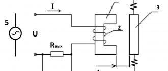
The connection diagram for a switch with LED backlight is shown in Fig. 1. The principle of its operation is based on Ohm's law and is quite simple. At the moment when the contacts of switch Q1 are open, the load current flows through the circuit L – R1 – LED – HL – N. The load current does not exceed the operating current through the LED, that is, 10 mA. Naturally, this current is not enough to light the main lighting lamp. For comparison, a 60 W incandescent lamp consumes 270 mA. In addition, the main part of the 220V network voltage drops not at the lamp, but at the resistor. As a result, only the LED lights up, and its brightness depends on the resistance of resistor R1.
As soon as the light is turned on in the room, the resistance of the switch contacts located parallel to the LED with the resistor will become close to zero. The current flow circuit will close through L – Q1 – HL – N. The load current will follow the path with the least resistance and the LED will go out.
By the way, if you unscrew the lamp from the lamp or it burns out, the backlight will stop working.
Calculating the backlight on an LED comes down to choosing the right resistor R1. The fact is that 99% of the mains voltage drops across it, which means the power dissipation is quite high. For example, given an LED current of 8 mA, let’s calculate the resistor parameters:
A resistor that dissipates almost 2 W of power will be large and heat up so much that it can deform it upon contact with the plastic case. Because of this drawback, the considered option has not found practical application.
In order to reduce heat losses and protect the LED from breakdown, the switch illumination circuit is supplemented with a rectifier diode (usually 1N4007) connected in series with the LED (Fig. 2).
In this case, not an alternating voltage of 220V is applied to the circuit elements, but a constant voltage - 0.45 times less, that is, approximately 100V. The resistor value can be set in the range of 12-50 kOhm and experimentally select an option in which the brightness of the illuminating LED and the temperature of the resistor surface will be optimal. The advantages of DIY LED lighting include the ability to independently choose the color of the LED, its size and installation location.
Illumination using a neon lamp
The circuit and principle of operation of a backlit switch with a neon lamp is completely identical to that with an LED, but has improved performance.
The main advantage of a neon light bulb is its extremely low current consumption, which does not exceed 1 mA, and ideally should be 0.1-0.2 mA. This allows you to install a limiting resistor of much lower power and size, namely: It turns out that a miniature resistor with a power of 0.125 W easily fits under the case and does not heat up at all. Compared to an LED circuit, this option is more economical, reliable and safe. And the service life of a neon lamp reaches 80 thousand hours. That is why backlit switches that use a neon lamp have found wider practical application.
What should you pay attention to?
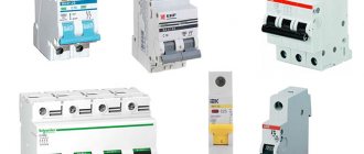
When choosing a switch with an indicator, it is necessary to operate with the power consumption of all lighting devices connected to the switch. The markings and rated current (maximum permissible) current are indicated on the inside of the switch. Basically, switches are manufactured for currents of 10 and 16 A and, accordingly, the maximum connection power for them is 2.2 and 3.5 kW. It should also be noted that you should not use backlit switches to work with energy-saving (fluorescent) lamps. Because when turned off, the energy-saving lamp flickers, and this “behavior” of the lamp is unlikely to please anyone.
Currently, there are special types of lighting devices - a flickering candle lamp, which imitate the fluttering of a flame in the wind.
Connecting a single-key switch with backlight
To assemble and then connect the backlit switch to a 220V network, you will need a little time and following the steps below in the instructions.
- It is necessary to de-energize the room in which the modernization and installation of a backlit switch will be carried out.
- Remove the light on/off switch by carefully prying it off from the sides with a screwdriver.
- Remove the switch from the wall and disconnect the wires.
- Depending on the shape and size of the housing, determine the installation location of the LED.
- Drill a hole with a diameter of 5 mm in the marked location.
- Solder a resistor to one of the LED terminals, and a diode to the second, observing the polarity.
- To avoid a short circuit, hide most of the leads together with the resistor under a heat-shrinkable tube, leaving the edges bare for connection to the terminals.
- If necessary, extend the assembled structure with wires.
- Use superglue to secure the LED in the hole.
- Clamp one of the backlight wires together with the “phase” into the switch terminal.
- Connect the other backlight wire, together with the wire going to the lamp, to the second terminal of the switch.
- Install the finished switch with LED in the reverse order.
If you plan to use a finished product, then points 4 to 9 are skipped.
Connection diagram
two-button switch connection diagram
single-key switch circuit
So, when the switch is disassembled, depending on what type of release you have chosen, you need to connect it.
The connection diagram is not much different. In any case, one wire (phase) comes to the switch, and one, two or three wires leave it if you connect a single-key, two-key and three-key switches, respectively.
Viko two-gang switch with backlight
However, despite the simplicity of the design, some people have questions about installing Viko backlit switches.
Indeed, many people choose these types of switches for their practicality.
The weak red glow of the indicator makes it easy to find the light switch in the dark and, undoubtedly, this has its undeniable advantages.
The indicators in Viko switches must be connected independently.
If you have chosen this type of design, then after removing the keys (as described above) you will find an LED with two red wires coming from it.
These wires must be connected in such a way that one of them is connected to the “input” at the bottom, and the second to one of the “outputs” at the top.
In this case, polarity does not matter. The indicator will light up when the switch key to which you connected it to the “output” is in the “OFF” state.
Connecting a two-key switch with backlight
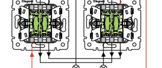
In 90% of cases, the design of a two-key backlit switch is no different from its single-key counterpart. The only exceptions may be exclusive models from foreign manufacturers. Basically, inside the switches with two lighting control keys there is one neon light bulb with a resistor, as shown in the photo.
It’s easy to guess that the backlight will light up and go out only when you press one of the keys. However, switch manufacturers do not see the need to install a second neon light, since one indicator light is sufficient for illumination in the dark.
The sequence of actions for assembling the backlight of a two-key switch is the same as for single-key models. We only note that the electrician, at the moment of connecting the wires, has the right to choose which key the neon light will go off when pressing. If we are talking about assembling the LED backlight with your own hands, then if you wish, you can install 2 LEDs - on each of the keys separately.
Peculiarities
I believe that you have already personally seen, or at least a photo of, a backlit switch, because when I was a child, we had such switches in our apartment. An old Soviet model of an illuminated switch, which had a small red light on top and was hidden behind matte, barely transparent plastic. Apparently, the idea was taken from my grandparents, because they had exactly the same switches in their house, or they were installed at the same time.
In any case, as personal experience shows, it is very convenient. At that time, no one had heard of walk-through switches, and therefore in the middle of the night they had to navigate the space by memory. Or rather, I would have to, because I was lucky, and there were such switches in the house. In complete darkness, they provided enough light to understand where you were, and actually where the switch was.
Modern types of backlit switches have become more neat and sophisticated. Designs are becoming quieter and smaller in size. The same applies to LED elements. Now their main task is simply to provide information in the dark about where the switch is.In addition, there are certain restrictions regarding the areas of use of such devices. They mainly concern portable light sources, or those that receive power from low-voltage lines.
Possible future problems
Even such a simple design as a switch illumination is not without its drawbacks. First of all, this applies to LED lamps, inside of which an electronic unit – a driver – is installed. Due to the presence of the backlight, there is a small potential on the base of the turned off LED lamp, which affects the operation of the driver. Since the circuitry of the drivers is designed differently, problems in the operation of the lamp can manifest themselves in different ways, namely:
- in the form of an unpleasant flicker;
- in the form of a dim glow of an LED lamp;
- The backlight may not work at all with some models of LED lamps - their driver breaks the electrical circuit.
Similar problems arise when a backlit switch interrupts the circuit of a fixture containing a compact fluorescent lamp, due to the presence of a switching power supply in it. Therefore, before buying a backlit switch or upgrading an existing one, you should be sure that an incandescent or halogen lamp will be connected to it. Otherwise, you should be prepared to eliminate negative flicker and dim glow.