What is it and why is it needed?
Valves equipped with an electric drive are used in pipelines transporting various non-aggressive media. They are installed in heating, sewer systems, and air conditioners.
They ensure efficient functioning of the system and simplify management processes. Such valves are installed on industrial lines and in places with difficult access to pipes.
The electric drive consists of a motor, gearbox, coupling and end position sensors. It can have an explosion-proof design for installation in a block of reversible magnetic starters.
Operating principle and device
This type of device can be used with different working media - liquids, gas, oil, oil and petroleum products. When selecting a valve, you should take into account the conditions of its operation - the material of the main elements must be corrosion resistant to the working environment, the unit must withstand the pressure of the environment, etc.
Some valves equipped with an electric drive allow the mechanism to operate not only in final positions, but also in intermediate positions. All products are equipped with a housing, a lid and a special O-ring seal that protects the device from leakage.
Electrically driven valves perform the functions of shut-off valves - they block the flow of the working medium and operate in three modes:
- Adjustment, used after valve installation or repair. In this case, commands are sent to the device sequentially. The electric drive “remembers” them for future use. Adjustment is carried out manually at the extreme positions of the shutter.
- Automatic, in which the electric drive is configured to change the flow parameters of the working medium. Sensors record changes in characteristics and send a signal to the circuit. The contacts close and the shutter closes.
- Remote. In this case, the operation of the electric drive is controlled using a remote control by the operator in manual mode.
Features of automatic mode
The electric drive allows you to use the device in automatic mode. To turn it on, you need to switch the 1PU switch to the “Automatic” position, and also move the VK toggle switch to the “on” position. In this case, switch 1VB must be turned off, and switch 2VB must be turned on.
Commands are sent to the circuit depending on the size of the characteristics by closing contacts 1РК and 2РК. Relay 1RL or 2RL is turned on, respectively, and the magnetic starters receive the sent command to fully open or close the valve. Command control is carried out by turning on the LO, LZ lamps.
The circuit has a special torque correction switch; it is possible to turn on a thermal switch to protect the system from overheating. Such products are also equipped with an auto-reset system.
Features of the setup mode
This mode is necessary to check the operation of the system after installation or repair. To turn it on, you need to turn the 1ВБ toggle switch to the “on” position and apply power by turning on the AB toggle switch. To check the operation of the electric motor, you need to press the 4KU button. If the valve opens, then everything is in order. Button 5KU closes the valve.
Giving the 4KU command closes contact PO1 and opens PO2. This is necessary to avoid sending a false signal. Then PO3 closes three power switches, and when the damper reaches its extreme position, a special limiter is activated.
Functions and principle of operation
Valves with electric drive perform the usual functions of shut-off valves - shut-off and control:
- block the pipe completely or partially;
- open the lumen of the pipe to release the flow.
We recommend that you read: Purpose and main types of HDPE ball valves for pipes
The electrically driven locking device operates in three modes:
- commissioning;
- automatic;
- remote
The adjustment mode of operation is used after installation or replacement (repair). Here, commands are sequentially sent (contacts are closed) to the electric drive, which it “remembers” and uses in further operation. Adjustment of the operation of the electric drive is carried out after installation, with manual adjustment of the extreme positions (open-closed).
Automatic mode is the operating mode of the shut-off device, when the electric drive is configured to change the flow parameters, its pressure, and temperature. Changes in parameters are recorded by special sensors. They “send a signal” to the control circuit, the contacts close, the magnetic drive is applied. The electric drive sets the shutting mechanism to the required position.
Remote mode is when the operation of the electric drive of the valve is controlled from the operator control panel in manual mode.
https://youtube.com/watch?v=c38-NoAvf20
https://youtube.com/watch?v=c38-NoAvf20
Technical characteristics of the valve with electric drive
When choosing a model of equipment, you need to pay attention to the markings. It includes the main parameters of the unit and its operating conditions. If the marking contains the letter “U”, then the valve can be used at an ambient temperature from −40 to +40 °C; “UHL” indicates the possibility of operation at a lower temperature - from −60 to +40 °C.
For southern regions with high air temperatures, special fittings marked “T” are produced. Its temperature range is from -10 to +50C.
The diameter of the products is selected based on the nominal diameter of the pipe. The power of the electric motor depends on the size of the housing and the diameter of the pipeline. Since the passage part of the housing has high hydraulic resistance, sufficient force is required to block the flow. It can be increased by increasing the power of the electric motor or changing the type of gearbox.
An important technical parameter of the product is the time for complete opening/closing of the pipeline. It can range from 30 to 80 seconds, depending on the type of valve and pipe diameter.
Electric gate valve control cabinet in 1 hour with modular assembly technology
Then the starters execute the specified mode to raise or lower the valve. This protection is carried out using magnetic starters and electromagnetic voltage relays.
Disadvantages This electric valve control circuit uses four limit switches of the limit switch block - two to turn off the control circuits, two to turn on the indication lights, which requires installing each limit switch separately. According to the method of arrangement of the running mechanism, they are distinguished: with a retractable spindle; with a non-retractable spindle.
The circuit provides for manual and automatic control of the electric drive. In this case, the 1RP relay will turn on, which closes its open contact in the power supply circuit of the PO starter coil.
2.3.3. Electrical control circuit
The adjustment mode of operation is used after installation or replacement of repairs. In this case, the 1RP relay will turn on, which closes its open contact in the power supply circuit of the PO starter coil. Electric - the valve is controlled by a moving spindle, which is the armature of the electric coil.
Potentiometer R is used as a position sensor. In this case, the following requirements must be met: Work in the order of routine operation, the list of works applies only to electrical installations with voltage up to V; The work is carried out by operational or operational-repair personnel on the equipment and area assigned to these personnel. Pneumatic - the spindle moves due to the pressure of compressed air on its surface. Advantages of the circuit As mentioned above, the valve indicator lights light up only at the moment when one or another limit switch actually operates.
Installation Features To install the valve on a pipe, flanges are welded to it, after which they are bolted to the designated location. Designed to control the movement of the damper in the assembly, it is represented by mechanical structures in the form of a flywheel moving on a retractable or stationary rod; pneumatic, electric and hydraulic drives are also used. These parameters will be saved for a long time in the non-volatile memory of the device and will remain unchanged even when the power is turned off. Automation of electric valve drives can be used not only in large industrial enterprises and urban water supply networks, but also in large households. The SA key installed in the signal lamp circuits HL1 and HL2 ensures operation of the automation panel with normally extinguished signal lamps.
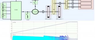
Features of valves with electric drive Technical characteristics of electric drive valves, depending on which electrical circuit diagram is used, allow you to have three control options: Remote mode uses a column for manual control. Hydraulic - hydraulic fluid exerts pressure on a movable rod with a valve placed in a sealed cylinder. Setting up limit switches on MEO-63
Classification of motorized valves
There are several types of electric shut-off valves. By design it is:
- Disc type, in which the locking unit (disk) moves perpendicular to the flow of the medium. Such models are distinguished by their simplicity of design, maintainability, and affordable cost. They are used in sewer systems and pipelines operating under low pressure.
- Klinova. The shutter mechanism is a wedge with a retractable/non-retractable spindle that fits into a wedge seat. They are used on pipelines transporting various media, on main lines.
- Parallel, with two parallel saddles with discs.
Based on the material used, valves are divided into cast iron and steel. The material is selected based on operating conditions - ambient temperature, liquid/gas aggressiveness, etc.
There are several types of electric actuators for shut-off valves: multi-turn, explosion-proof, integrated.
Multi-turn
These valve models are distinguished by the presence of a complex system for remote signal reading. Such valves can be installed in any position, not just open/closed. This allows them to be used to regulate flow.
Explosion-proof
Valves with an electric drive in an explosion-proof state guarantee increased protection of the device from the effects of negative environmental factors. They are actively used at various production enterprises in the oil and gas sector and in the chemical industry. Can be installed in hazardous areas.
Integrated
These devices are equipped with a special controller that communicates with the automated control system. The sensor system allows you to monitor the current state of the flow, and the program remotely programs the operation of the valve.
Advantages and disadvantages
The advantages of valves with electric drive include:
- The ability to quickly regulate the flow of the working medium in the pipeline.
- Automatic control.
- Closing and opening the locking mechanism in the fittings of any DN without the use of physical effort.
- Remote control of the flow of the working medium, installation in places hard to reach for humans.
- Corrosion resistance.
- Resistance to hydraulic shocks.
- Easy to control via cabinet or remote control.
There are also disadvantages. For example, such fittings require an uninterrupted supply of electricity to function. There is a possibility of depressurization when using low-quality gaskets.
Areas of application
Shut-off valves equipped with an electric drive are used on domestic and industrial pipelines, on main lines with a pipe diameter from 1.5 to 200 cm. It allows you to automate the supply and removal of the working medium.
Valves are used:
- In pipeline sections where access for manual adjustment of the system is difficult.
- In places dangerous to humans.
- Where automatic flow control is required.
Most often, electric valves are used in water pipelines transporting hot and cold water and technical fluids. The most common DUs are 50, 32 and 100 mm. In nuclear energy, it is possible to use valves with a smaller nominal diameter.
Electrically driven rack and pinion valves are used in submersible pumps to regulate water supply automatically.
Functions and principle of operation
Valves with electric drive perform the usual functions of shut-off valves - shut-off and control:
- block the pipe completely or partially;
- open the lumen of the pipe to release the flow.
We recommend that you read: Using plastic fixing clamps for securing pipes
The electrically driven locking device operates in three modes:
- commissioning;
- automatic;
- remote
The adjustment mode of operation is used after installation or replacement (repair). Here, commands are sequentially sent (contacts are closed) to the electric drive, which it “remembers” and uses in further operation. Adjustment of the operation of the electric drive is carried out after installation, with manual adjustment of the extreme positions (open/closed).
Automatic mode is the operating mode of the shut-off device, when the electric drive is configured to change the flow parameters, its pressure, and temperature. Changes in parameters are recorded by special sensors. They “send a signal” to the control circuit, the contacts close, the magnetic drive is applied. The electric drive sets the shutting mechanism to the required position.
Remote mode is when the operation of the electric drive of the valve is controlled from the operator control panel in manual mode.
Features of installation of electric valves
Installation of fittings with an electric motor must be carried out by a trained team of installers. Before starting work, you need to remove all plugs, degrease the device, and check its functionality.
Gate valves are mounted in a vertical or horizontal position with the stem up. For fittings with a diameter of more than 100 mm, carefully provide for the installation of a fixed support.
The method of installation of fittings is selected based on the material of the housing and the requirements for the pipeline. After installation, the connection is checked for leaks. Cast iron valves are installed using flanges, while steel valves are installed using a welded or flanged method.
At the final stage, you need to assemble a control circuit consisting of a power part and automation that supplies signals. The electrical part is located in the electrical cabinet installed near the valve.
Then pneumatic and hydraulic tests are carried out as part of the pipeline system, checking the functionality of the electric motor.
Installation features
Installation of electrical fittings is often carried out only by qualified teams. Before starting the installation, the device must be decondensed, excess lubricant must be removed, plugs must be removed and performance checked. All technical parameters specified in the product passport must fully comply with the pipeline data.
Installation can be performed in both vertical and horizontal positions. It is not recommended to install the valve upside down, as dirt will collect near the rod, and this will gradually lead to jamming of the spindle. Valves with an electric drive with a diameter of more than 10 cm must be equipped with an additional fixed support.
Connecting the device to pipelines directly depends on the material from which it is made. For example, a cast iron valve is connected using flanges. To do this, you will have to weld the same abstract elements to the ends of the pipes. This connection, thanks to bolts and a rubber gasket, ensures high tightness. Welding defects cannot be compensated for by adding additional seals.
After installation is completed, assembly of the mechanism control unit begins. It includes elements of automation, as well as a power unit. The first ones send a signal from the button to the drive. The power part is located in an electrical cabinet installed near the valve. The last step will be to check all types of controls.
Hydraulic tests are performed on the connected structure. Defects found cannot be eliminated by tightening bolts. Installation can only be considered complete after all checks have been carried out.

