Differences and types of stepper motors
According to the principle of operation, they are closer to DC motors. The design of electric motors is constantly being improved to reduce labor costs in manufacturing, increase efficiency and increase the number of revolutions. Compared to a DC motor, they have no brushes, no commutator, and windings with fewer turns.
Among the first engines was a miniature engine for wrist watches and named after the French engineer Marius Laveta. The stator is disengaged at the edges or has slight constrictions in the rotor area. Rotor with a diameter of 1.5 mm, magnetic based on cobalt. One winding in one row is powered by 1.5 volts. Rotation angle is 90 degrees.
The Lavet motor is also used in medicine for pumping various liquids, and is also often used in mixers and blenders.
Recently, piezoelectric motors have been developed using the piezomagnetic effect and using ferromagnetic materials in the design. Linear electric motors are being improved, in which the shaft does not rotate, but performs linear movements. For precision mechanics equipment, Russian manufacturers produce motors with the following series markings:
DS.- DShR.
- DShG.
- DSHL.
- SD.
- DSE
The following enterprises participate in their production: NPO ATOM, ZETEK, Elektroprivod, Stepmotor, Vekson, NPO RIF, Saratov El. mechanical, VNIIEM corporation, Uralelectromash CJSC, Energoservice ARK. The production of SD FL 203, FL 28, FL 57, 35 HS, 57 HS, 17 HD is carried out by foreign companies: Fulling motor, Autonics, Motionking YUHA motor, Jlangsu, Phytron and others. The range of produced motors is varied: in standard sizes, power, with a built-in gearbox and control board.
Connecting a stepper motor to the AVR ATmega16 microcontroller
Stepper motors are brushless DC motors that can rotate from 00 to 3600 in discrete steps. With each control signal, the axis of such a motor rotates by a fixed value (step). The rotation of such motors is controlled by a sequence of special signals. Unlike servo motors, stepper motors can be controlled by general purpose I/O pins rather than just PWM modulation pins, and can be rotated at (+3600) and (-3600). The sequence of control signals determines whether the stepper motor will rotate clockwise or counterclockwise. To control the rotation speed of such an engine, you simply need to change the level of control signals. Stepper motors have several modes of step (discrete) rotation - full step, half step and microstep.
In this project we will connect a 28BYJ-48 stepper motor to an ATmega16 microcontroller (AVR family) using Atmel Studio 7.0 software. The stepper motor will operate with a supply voltage of 5V. We will connect the stepper motor to the microcontroller using ULN2003 and L293 motor drivers (separately). Both will be powered by 5V.
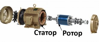
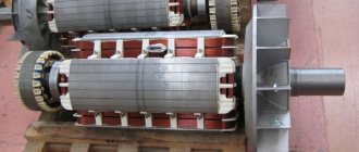
Design and operating principle
A stepper motor consists of a stator and a rotating rotor. The stator core is made in the form of a set of electrical steel sheets (stamped). This reduces eddy currents and therefore heating. The stator is divided around its circumference into 4.6.8 longitudinal grooves. More are used. Windings in the form of coils are located on the protrusions between the grooves. The number of slots corresponds to the number of motor poles. The more poles, the smaller the angle of rotation of the rotor, that is, the pitch.
The rotor consists of one or two permanent magnets , at the ends, the metal plates of which are fixed with teeth. In this case, the pluses S and N of the permanent magnet are divided into n poles, which corresponds to the number of teeth. This also affects the rotation step size. According to the design, motor motors are produced in three types depending on the rotor design:
- reactive;
- permanent magnet rotor;
- hybrid.
Reactive - the rotor is made of ferromagnetic material with longitudinal grooves and poles. It is rarely used, only for simple tasks. Mainly because it has no stopping torque. Hybrid - the rotor is made of two halves of ferromagnetic material, with longitudinal grooves and a permanent magnet located between them. The grooves of the halves relative to each other are shifted at a small angle to reduce the pitch. They are most often used.
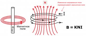
When a pulse voltage is applied to the stator winding, an electromagnetic field is generated. By interacting with the nearest pole of a permanent magnet, a torque is created. The motor shaft rotates at a certain angle. The rotation angle mainly depends on the number of rotor poles.
Such a motor will be called a stepper motor. Due to its small size, the Em 422 series SD is used in dot matrix printers.
Operating principle of a bipolar stepper motor
The following figure shows the working diagram of a bipolar stepper motor. You can read about another type of stepper motors - unipolar - in the relevant sources. A bipolar stepper motor typically has four coils. The coils, located one opposite the other, are connected so that they work synchronously. All the coils are located on a stationary motor stator, which means there is no need for a rotating commutator and brushes like with DC motors.
The rotor of a stepper motor is made in the form of magnetized teeth with alternating north (N) and south (S) poles (there are usually many more teeth on the rotor than shown in the figure shown). Each coil can be connected so that it is magnetized either as a north pole or as a south pole, depending on the direction of the current in the coil. Coils 1 and 3 work together so that when coil 1 is the south pole, coil 3 will also be the south pole. The same applies to coils 2 and 4.
Let's start with the variant of the drawing under the letter "a" - when coil 1, and therefore coil 3, are powered so that they become south poles (S), due to the fact that unlike poles attract and like poles repel, the rotor turns counterclockwise until until the nearest rotor teeth with the magnetization of the north pole (C) align with coils 1 and 3 (as shown in “b”). To continue counterclockwise rotation, in the next step (Figure “c”) it is necessary to apply current to coils 2 and 4 so that they become the north poles (C). Then the nearest rotor teeth with magnetization Yu will be pulled towards coils 2 and 4 (Figure “d”).
Each such action rotates the electric motor rotor one step. To continue counterclockwise rotation, magnetization C must again be created in coil 1 (see the table presented).
Table 1. Sequence of actions when rotating a stepper motor counterclockwise
| Coils 1 and 3 | Coils 2 and 4 |
| YU | — |
| — | WITH |
| WITH | — |
| — | YU |
The dashes in the columns of Table 1 indicate that the coil at this moment does not affect the rotation of the rotor and should be de-energized. To increase the rotational torque of the engine, such a current can be supplied to these de-energized coils so that the polarity of their magnetization coincides with the polarity of the rotor tooth underneath it (Table 2).
Table 2. Refined sequence of switching coils when rotating a stepper motor
| Coils 1 and 3 | Coils 2 and 4 |
| YU | WITH |
| WITH | WITH |
| WITH | YU |
| YU | YU |
To change the direction of rotation of the rotor, you just need to reverse the order of switching the coils indicated in Table 2.
Phase control methods
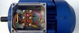
The control mainly depends on the number of poles and the configuration of the stator windings. SD motors are produced mainly with the following windings:
- Two windings with 4 terminals.
- Two windings with 6 wires with a middle terminal.
- Four windings - 8 pins.
You can control it in two ways: use unipolar voltage - unipolar or bipolar - bipolar. A unipolar stepper motor has 4 poles and 2 windings. In a four-phase winding, each winding is divided in half and located on opposite poles. Rotation is carried out by alternately applying voltage to the windings. With 6 pins or 5, there are also 2 windings, but with a tap from the middle. Typically, the middle terminals of the coil are connected together to the negative wire, and the positive wire is fed through controlled switches to the windings.
Motors with bipolar control have 4 windings, 2 for each phase. Control occurs when the polarity of the winding is changed. With this control, the connection diagram of the stepper motor becomes more complicated, but the torque obtained is greater. The main characteristics are supply voltage, phase current consumption, pitch, power and flange size. The mounting locations are standardized and specified as, for example, Nema 23. This corresponds to a distance between mounting holes of 57 mm.
Connecting the stepper motor
Today we will try to connect a stepper motor Atmega8a .
Stepper motors are motors that, by applying voltage to a specific winding, move their rotor to a specific location, thereby achieving more precise control of the angular velocity. You can also, in principle, control the position of the rotor, but these are somehow more servos, which we may also encounter someday.
Stepper motors are gaining more and more interest nowadays, since in our age of precision electronics people make something moving, like robots and some smart machines, and it also comes down to certain aircraft and other devices.
Therefore, I also did not ignore this issue and decided to also tell something about it and connect the stepper motor to the controller and try to control it. As soon as I succeeded, I decided to share it with you.
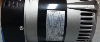
I came across just such a stepper motor 28-BJ48 from Kiatronics
This motor is powered by 5 volts, the power is supplied alternately to different windings, of which there are 4, and if the power is removed from one winding and supplied to another, then the rotor. respectively. rushes towards her.
These windings with their cores in the stator are not located in 4 places, but much more often, namely, each is repeated 2048 times, so when we apply voltage to the adjacent winding, the rotor rotates at a very small angle. And if voltage is also applied to 2 adjacent windings, then the rotor can be placed between them, and the number of positions generally doubles. And there is generally a microstepping mode, when we apply less voltage to one winding and more voltage to the other, then you can generally get lost in the number of steps and generally turn this stepper motor very smoothly.
It is better to power the engine not from the controller legs, but rather through some kind of decoupling. You can use powerful transistors, but there is a special driver chip for stepper motors. As a rule, this driver is produced in the form of ready-made modules that look something like this together with a connected stepper motor
This module is a ULN2003 chip. You can use it not only for engines. But we will use 4 inputs and 4 outputs here since our motor has 4 wires. each of which is connected to a specific winding, and the fifth wire is common. A motor connected in this way no longer affects the pins of the ports, which have a limited maximum current, and you can no longer be afraid of anything in this regard. When connecting to the controller legs, we use the module inputs IN1, IN2, IN3 and IN4, and simply connect the motor connector to the module connector.
Let's draw a diagram like this to better understand the principle of operation of the engine (to see the drawing process, watch the video version of the lesson, the link to which is at the bottom of the page)
Here we see 4 coils, one terminal of which is connected to a common wire, and we will apply logical levels to the other terminals of each coil, for example, 1000 is applied in the figure.
These windings are then repeated cyclically in a circle.
Now let's look at possible control modes using logical levels.
Mode 1 is the simplest mode, in which we alternately apply logical ones or high logical levels to each winding. It is also called full-step mode or One Phase Step Mode .
This mode can be schematically represented as follows:
There is also another interesting mode - this is the mode when the rotor will walk between the windings, that is, we will apply units to 2 adjacent windings
And there is also a third solution - this is a half-step mode, when we alternate combinations, first the rotor will be located at the winding, then it will move halfway to the adjacent winding, then completely to the neighboring winding, etc. Is it half-step mode or one and two-phase-on
There are three such modes. we will focus on mode 3, as it will be the smoothest and most interesting.
In the next lesson we will assemble our entire circuit with a stepper motor and start writing some source code.
The 28YBJ-48 programmer and stepper motor with ULN2003 driver can be purchased here:
Watch VIDEO TUTORIAL (click on the picture)
Source
Ways to control a stepper motor
The use of motor drives in CNC machines competes only with servo drives, for example, in erosion machines or printers, they even surpass them in their technical capabilities, cost and simple control circuits. Control can be carried out on digital microcircuits, specialized - A3977, on a programmed PIC16, through keys or SMSD 1.5 drivers.
Most drivers are controlled by a computer via RS-232, USB and LPT ports. They generate control signals: step, direction, resolution and provide step division by ½ to 1/32 and work with programs: MACH3, KCam, DeskCNC, Turbocnc and others. Connect the motor to the driver using a cable according to the description. Once you've learned how the program works, it's easy to put it to work. To turn on, a voltage from 5 volts to 48 volts is used. Exceptions include 220/110 volt motors .