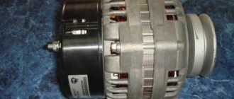
Rotor and stator
The easiest way to understand the concepts of rotor and stator. Because their physical condition determines their name. In other words, the terms rotor and stator refer to parts of electrical machines with respect to the physical movement of these parts relative to each other. In addition, each of these terms always refers to the same specific and unchanging part of the electric machine. It’s a little more difficult to understand what an armature and an inductor are. Since they can mean completely different parts of machines in different conditions.
Presumably the word stator comes from the Latin sto - standing. And already from Latin the English stator was formed. That is, the stator is a stationary (static) part of an electric generator or electric motor. In order for an electric machine to do any work, the stator must interact with the rotor. This interaction occurs through electromagnetic induction.
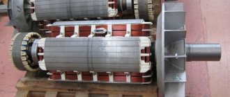
Stator and rotor of an asynchronous electric motor
The word rotor probably comes from the Latin rota - wheel, roto - spinning. That is, the rotor represents the moving (usually rotating) part of an electrical machine. The rotor is made mainly in the form of a cylinder or disk. By design, the rotor is connected to some kind of shaft. Through this shaft, it is either driven (generator) or itself drives a machine (electric motor).
What is a rotor
A rotor, also sometimes called an anchor, is a moving, that is, rotating part in a generator or electric motors, which are widely used in household and industrial appliances.
If we consider the rotor of a DC motor or a universal commutator motor, then it consists of several main components, namely:
- Core. It is made of many stamped thin metal plates, insulated from each other by a special dielectric or simply an oxide film, which conducts current much worse than pure metal. The core is made up of them and is a “layer cake”. As a result, electrons do not have time to accelerate due to the small thickness of the metal, and the heating of the rotor is much less, and the efficiency of the entire device is higher due to reduced losses. This design solution was made to reduce Foucault eddy currents, which inevitably arise during engine operation due to magnetization reversal of the core. The same method of dealing with them is used in AC transformers.
- Windings Copper wire, coated with varnish insulation, is wound around the core in a special way to prevent the occurrence of short-circuited turns, which are unacceptable. The entire winding is additionally impregnated with epoxy resin or varnish to fix the windings so that they are not damaged by vibrations from rotation.
- The rotor windings can be connected to a commutator - a special block with contacts securely fixed to the shaft. These contacts are called lamellas, they are made of copper or its alloy for better transmission of electrical current. Brushes, usually made of graphite, slide along it, and at the right moment electric current is supplied to the windings. This is called sliding contact.
- The shaft itself is a metal rod, at its ends there are seats for rolling bearings; it may have threads or recesses, grooves for a key for attaching gears, pulleys or other parts driven by an electric motor.
- A fan impeller is also placed on the shaft so that the engine cools itself and does not have to install an additional device for heat removal.
It is worth noting that not every rotor has windings, which, in essence, are an electromagnet. Instead, permanent magnets can be used, as in brushless DC motors. But an asynchronous motor with a squirrel-cage rotor does not have windings in the usual form; instead, squirrel-cage metal rods are used, but more on that below.
Which rotor is better, phase or squirrel cage?
Advantages of short-circuited:
- More or less constant speed regardless of different loads
- Acceptability of short-term mechanical overloads
- Simple design, ease of start-up and automation
- Higher cos φ (power factor) and efficiency than wound rotor motors
Flaws:
- Difficulty in regulating rotation speed
- High starting current
- Low power coefficient at underload
Advantages of phase:
- High starting torque
- Acceptability of short-term mechanical overloads
- More or less constant speed at different overloads
- Lower starting current than squirrel cage motors
- Possibility of using automatic starting devices
Flaws:
- Large dimensions
- Power factor and efficiency are lower than squirrel cage motors
From simple inventions to the electric motor
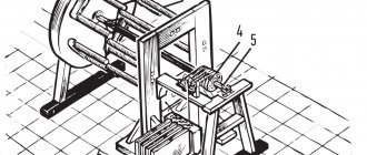
After a number of his discoveries, J. Henry made a magnetic circuit with a coil, which was installed horizontally, like the beam of a laboratory scale. When the armature swung, the contacts attached to the ends of the rocker touched the terminals of two galvanic cells, which fed the coil with currents of different directions. While swinging, the rocker was attracted to two permanent magnets that were part of the system.
The installation could operate continuously, imparting 75 swings to the armature per minute. This is how one of the first designs of a reciprocating electric motor arose. And turning it into a rotational motion engine at that time was not difficult. It is worth noting that machines with reciprocating motion were not popular at that time, since electric motors with a rotating armature were considered technologically more convenient.
Later came the era of three-phase alternating current. The rotating components of an AC motor are no longer called an armature. The rotating magnetic field began to be called a vortex, and the rotating part - a rotor. However, in DC machines the terminology has been preserved. The armature rotated, and the pole piece was called a shoe.
Today, multiphase linear electric motors for monorail trains are becoming widespread. A tightly attached monorail is used as a rotor, and windings that are installed on the magnetic core of fast-moving electric trains serve as the stator.
The company ZAO PromElektroRemont has all the necessary certificates for the provision of such work as:
- Repair and rewinding of electrical equipment;
- Repair of welding transformers;
- Repair of pumps, including deep ones;
Other events
Three-phase squirrel-cage asynchronous motor
Construction of an asynchronous electric motor
Stator
consists of a body and a core with a winding. The stator core is assembled from thin sheet technical steel, usually 0.5 mm thick, coated with insulating varnish. The laminated core design contributes to a significant reduction in eddy currents arising during the process of magnetization reversal of the core by a rotating magnetic field. The stator windings are located in the slots of the core.
Rotor
consists of a core with a short-circuited winding and a shaft. The rotor core also has a laminated design. In this case, the rotor sheets are not varnished, since the current has a low frequency and the oxide film is sufficient to limit eddy currents.
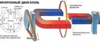
Principle of operation. Rotating magnetic field
The operating principle of a three-phase asynchronous electric motor is based on the ability of a three-phase winding to create a rotating magnetic field when connected to a three-phase current network.
The rotation frequency of this field, or the synchronous rotation frequency, is directly proportional to the frequency of the alternating current f1 and inversely proportional to the number of pole pairs p of the three-phase winding.
,
Rotating magnetic field concept
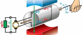
To understand the rotating magnetic field phenomenon better, consider a simplified three-phase winding with three turns. Current flowing through a conductor creates a magnetic field around it. The figure below shows the field created by three-phase alternating current at a specific point in time
The components of alternating current will change over time, causing the magnetic field they create to change. In this case, the resulting magnetic field of the three-phase winding will take different orientations, while maintaining the same amplitude.
The effect of a rotating magnetic field on a closed loop
Now let's place a closed conductor inside a rotating magnetic field. According to the law of electromagnetic induction, a changing magnetic field will give rise to an electromotive force (EMF) in the conductor. In turn, the EMF will cause a current in the conductor. Thus, in a magnetic field there will be a closed conductor with a current, on which, according to Ampere’s law, a force will act, as a result of which the circuit will begin to rotate.
The influence of a rotating magnetic field on a closed conductor carrying current
Features of the asynchronous motor of the angle grinder
Almost all electrical appliances used in everyday life use an asynchronous electric motor.
An important advantage of this type of motor is that when the load on it changes, the speed does not change. This means that if, for example, you cut stone for a long time and without stopping with a household grinder, there will be no noticeable external signs of engine overload. The disk rotation speed will be constant, the sound will be monophonic. Only the temperature will change, but this may not be noticed if your hands are wearing gloves.
If you are not careful, an advantage can turn into a disadvantage. Asynchronous motors are very sensitive to overheating; a significant increase in operating temperature entails melting of the insulation on the rotor windings. At first, the motor will work intermittently, and then - when an interturn short circuit occurs - the motor will stop completely. If you overheat the grinder's engine several times, it is most likely that the anchor will melt. In addition, the high temperature causes the contacts connecting the wires of the primary winding to the collector to become unsoldered, which leads to an interruption in the supply of electric current.
Principle of operation
The design and design features of an asynchronous motor also determine the operating principle of this unit. When voltage is applied to the stator winding, a magnetic field is formed in it. This voltage supply leads to changes in the magnetic flux and the entire magnetic field of the stator. The changed magnetic fluxes enter the rotor, drive it, after which it begins to rotate. In order for the stator and rotor to operate asynchronously, the voltage and flux values are required to be equal to the alternating current used as the power source.
The engine itself works as follows:
- The rotating magnetic field acts on a short-circuited winding specially adapted for rotation.
- The field crosses the conductors of the rotor winding, inducing an electromotive force in them.
- Under the influence of force, an electric current will begin to flow in the rotor conductors, interacting with the rotating magnetic field. This leads to the appearance of electromagnetic forces acting on the rotor winding.
- In total, the actions of the applied forces cause the appearance of a torque that causes the rotor to rotate in the direction of the magnetic field.
The magnitude of the induced emf depends on the frequency of the intersection of the conductors with a rotating magnetic field. That is, the higher the difference between n1 and n2, the greater the EMF value will be. The rotor will rotate at a frequency n2, which will always lag behind the synchronous frequency of the stator field n1. This difference between both frequencies will be the slip frequency ∆n= n1- n2. This inequality is a necessary condition for the appearance of electromagnetic rotating torque in an asynchronous motor. That’s why the unit is called that, since the rotor rotates asynchronously with the stator field.
Best answers
Elektroburatino:
You see, dear Sergey XXX, the question, as I understand it, is a tricky one... Most likely, NOTHING!! ! This is the same name for a part of an electric current generator or an electric motor... I just don’t understand one thing - WHY ARE SUCH QUESTIONS NEEDED?? ? Do you really need answers to these questions? ? Or did you just want to flirt (make fun)?!..
Larisa Dementieva:
Is it true? The rotor is something that is in rotation, and the anchor forces it to remain in stagnation.
Vasya:
armature in DC motors, rotor in AC motors.
Sailor:
This is the name of one part that rotates inside the stator. Difference. There is no winding on the rotor, but there is one on the armature.
realist:
The rotor in DC electric machines is called an armature.
Amir Kstaubaev:
The rotor is the entire rotating part of the electric motor. engine (from the beginning of the motor shaft to the end of the shaft!!! and the armature is that part, round, where exactly the winding with steel plates goes where the EMF is formed!!!! (The rotor is the entire rotating part of the electric motor. Entirely. And the armature is that part of the rotor , where the winding of the electric motor is located in which the EMF is induced. In this photo, the armature along with the windings is indicated by the number four.)
Anatoly Lapshov:
unfortunately, the armature and the rotor are completely different parts, for some reason they don’t put a rotor on the electromagnet, and in non-rotor asynchronous motors there is a short-circuited armature, also now they call a die, but is it possible to cut a thread with a die without a tool? Yes, of course, people who studied in at the crossings it seems to them that all the same educated people were kicked out
How does an asynchronous motor work?
The stator creates a rotating magnetic field. The direction of the tension lines is determined by the gimlet (right hand) rule. Therefore, let’s put the stator aside for now and try to understand what is happening in parallel on the rotor. Let's start with the squirrel cage.
Inside the stator there is a field, the lines of intensity of which, to a first approximation, are directed towards the center where the shaft is located. The conductor of the squirrel cage is crossed at an angle of approximately 90 degrees. According to the right-hand rule, an alternating field induces an emf, which generates a current. The result is an answer.
Any pair of conductors in a squirrel cage turns into a frame. The stator field rotates around it. According to the rule of hand, a response field appears, directed opposite to the original one:
- The rotor moves slower than the stator. Let the rotation describe the clock hand.
- At some point, the north pole begins to catch up with one of the conductors of the squirrel cage.
- The current is directed so that the circular lines of the reciprocal magnetic field intensity go towards the pole.
- It turns out that ahead of the course the pole encounters the charge sign of the same name and begins to push it. A “south” forms behind, trying to run after the field.
Operating principle
A simple short explanation of why a squirrel cage eventually starts to spin. The rotor should not be too heavy, the adhesion of the fields is not very strong. This explains the low traction force developed by the asynchronous motor at the start. The inrush current is high because there is nothing to prevent the field from being generated within the stator. Please note: in the rotor of a single-phase asynchronous motor, shown in the photo at the beginning of the article, the conductors of the squirrel cage are slightly inclined to the axis of the drum. Helps create a more uniform magnetic pole, compensating for the shortcomings (primarily unevenness) of the rotation of the stator field.
The phase rotor consists of windings, the normal of which is directed approximately to the center of the motor (shaft). You can imagine each one as a hypertrophied cell of a squirrel cage. There are many turns (in drills, for example, about 40), the field strength is much higher. Due to the sharp jump at the start, the energy consumption would become too large. The level of EMF is significant (determined by the rate of change of magnetic flux). The rotor circuit is supplemented with a rheostat, trying to compensate for the deficiency. Active resistance reduces the current, naturally reducing the response field generated by the conductors.
A wound rotor can improve the characteristics of asynchronous electric motors; two or three conductors (roughly speaking) provide greater traction force. The disadvantages of the technical solution include the presence of current collectors and a brush apparatus. To reduce wear in some asynchronous motors, after gaining speed, the rotor is short-circuited by a special mechanism. The life of the equipment is greatly extended.
We see no reason to consider the wound rotor in more detail; a reinforced squirrel cage would serve as a better illustration. Imagine: instead of one there are forty pieces! The amount (from 40 and down) is regulated by the resistance of the rheostat.
Definition
From the point of view of electrical engineering, a classic rotor is a rotating cylindrical body with the following structure:
- Shaft made of durable tool steel with at least two bearings, one each at the front and rear;
- Cores made of thick metal plates;
- Coils wound on cores assembled from plates;
- A collector or a pair of special conductive rings.
For forced air cooling of a part rotating very often at high speed, an impeller located at one of its ends is used. In generators, rotation is transmitted to the rotor from a turbine connected to it through a common shaft, or from a running engine using a pulley on which a flexible and durable belt is worn (V-belt drive).
So, the main function of the rotor is rotation relative to the stationary part. In electrical engineering, such a stationary part is the stator. Together, the rotor and stator are the most important components of electric motors and alternators.
Asynchronous motor device
The design of an asynchronous motor is quite simple:
- The stator is the stationary part of the electric motor, which is equipped with field windings.
- The rotor is a rotating element of the motor that rotates under the influence of a magnetic field created by field windings located on the stator. There are 2 types of motors depending on the rotor design: squirrel-cage and phase.
- Flanges are a static part of an electric motor that contains support bearings that hold the rotor and are a kind of fastener for the stator. It is clamped between two flange covers with coupling bolts. Or they are screwed to the stator housing.
- The terminal box is a part of the static motor structure into which the ends of the windings from the stator are led out. Through it, the motor is connected to the control circuit.
- Impeller and protective casing - used to provide forced ventilation, and the casing will protect operating personnel from injury.
- Additional service windings - if necessary, together with the excitation winding on the stator, there can be an additional one designed to control and measure the operating parameters of the motor during its operation.
- Thermal sensors - industrial asynchronous motors, in addition to the windings, there are also temperature sensors that monitor overheating in case of a sharp increase in current consumption.
Read also: Weld heating registers from pipes
Also, engines can be equipped with planar gearboxes and manufactured in a single housing. These are mainly industrial types of units used on machines, conveyors and other types of equipment.
Three-phase squirrel-cage asynchronous motor
, in which the rotor is made with a short-circuited winding in the form of a squirrel cage
Construction of an asynchronous electric motor
A three-phase asynchronous electric motor, like any electric motor, consists of two main parts - a stator and a rotor. The stator is the stationary part, the rotor is the rotating part. The rotor is placed inside the stator. There is a small distance between the rotor and stator, called an air gap, usually 0.5-2 mm.
Stator
consists of a body and a core with a winding. The stator core is assembled from thin sheet technical steel, usually 0.5 mm thick, coated with insulating varnish. The laminated core design contributes to a significant reduction in eddy currents arising during the process of magnetization reversal of the core by a rotating magnetic field. The stator windings are located in the slots of the core.
Rotor
consists of a core with a short-circuited winding and a shaft. The rotor core also has a laminated design. In this case, the rotor sheets are not varnished, since the current has a low frequency and the oxide film is sufficient to limit eddy currents.
Principle of operation. Rotating magnetic field
The operating principle of a three-phase asynchronous electric motor is based on the ability of a three-phase winding to create a rotating magnetic field when connected to a three-phase current network.
A rotating magnetic field is the basic concept of electric motors and generators.
Rotating magnetic field of an asynchronous electric motor
The rotation frequency of this field, or the synchronous rotation frequency, is directly proportional to the frequency of the alternating current f1 and inversely proportional to the number of pole pairs p of the three-phase winding.
,
Rotating magnetic field concept
To understand the rotating magnetic field phenomenon better, consider a simplified three-phase winding with three turns. Current flowing through a conductor creates a magnetic field around it. The figure below shows the field created by three-phase alternating current at a specific point in time
Anchor
The electrical engineering term armature usually refers to one of the parts of electrical machines that have windings. However, this term may also refer to the moving part of the magnetic circuit of a relay or electromagnet. In electric machines, the armature can be either a stator or a rotor. It all depends on the circumstances. GOST 27471-87 (Rotating electric machines. Definitions) gives the armature this designation
The part of a DC commutator machine or an AC synchronous machine in which an emf is induced and a load current flows.
Typically, in practice, the concept of armature refers to the part of the electric motor through the windings of which the electric current of the network flows during operation. That is, the armature is that part of the electric motor to the windings of which power is connected (working winding). For a generator, the armature means that part from which the generated voltage is removed. For example, in a brushed DC motor the armature is the rotor. And in a brushless DC motor, the armature will be the stator. For synchronous alternating current generators, most often the armature is the stator. Although in some low-power generators, the armature is a rotor from which the generated voltage is removed through brushes.
DC motor armature
An example of an armature is most rotors from motors for inexpensive hand-held power tools. Because in such tools the electric motors are commutator. That is, there is a collector on the rotor, to which voltage is supplied using graphite brushes. In other words, all rotors with commutators are armatures. However, the commutator should not be confused with the slip or slip rings located on the rotor of some electric machines. Slip rings have a continuous, uniform circle arrangement. The collector consists of many plates - lamellas, isolated from each other.
What is a stator
The stator is the stationary part in an electric motor. Usually it is combined with the device body and is a cylindrical part. It also consists of many plates to reduce heating due to Foucault currents, which are necessarily varnished. At the ends there are seats for sliding or rolling bearings.
The design is called a stator package; it is pressed into the cast iron body of the device. Inside this cylinder, grooves are machined for the windings, which, just like for the rotor, are impregnated with special compounds so that the heat is distributed more evenly throughout the device and the windings do not rub against each other due to vibration.
The stator windings can be connected in different ways depending on the purpose and type of electrical machine. For three-phase electric motors, star and delta connection types are applicable. They are presented in the diagram:
To make connections, a special distribution box (“boron”) is provided on the device body. The beginnings and ends of three windings are brought into this box and special terminal blocks of various designs are provided, depending on the power and purpose of the machine.
There are serious differences in the operation of motors with different winding connections. For example, when connected with a star, the engine will start smoother, but it will not be possible to develop maximum power. When connected in a triangle, the electric motor will produce all the torque declared by the manufacturer, but the starting currents in this case reach high values. The power grid may simply not be designed to handle such loads. Using the device in this mode is fraught with heating of the wires, and in a weak place (these are junctions and connectors), the wire can burn out and lead to a fire. The main advantage of asynchronous motors is the convenience of changing the direction of their rotation; you just need to swap the connections of any two windings.
Device and principle of operation
The current in the stator windings creates a rotating magnetic field. This field induces a current in the rotor, which begins to interact with the magnetic field in such a way that the rotor begins to rotate in the same direction as the magnetic field.
The relative difference between the rotor speed and the frequency of the alternating magnetic field is called slip. In steady state the slip is small: 1-8% depending on power.
Asynchronous motor
You can read more about the principles of operation of an asynchronous electric motor - in particular, using the example of a three-phase current unit, here on the website, in one of our materials. Next, we will look at what types of asynchronous electrical machines there are.