Differences from an inverter device
Such equipment differs from transformer equipment in the following characteristics:
- Light weight. If the mass of the transformer is about 35 kg, then for the inverter it does not exceed 15 kg. This makes it easy to move the device during operation.
- No transformer in the design. This eliminates energy consumption for heating the windings and magnetization reversal of the magnetic circuit. The efficiency increases. When using an electrode with a diameter of 3 mm, energy consumption does not exceed 4 kW. Under the same conditions, this parameter for the transformer is 7 kW.
- Possibility of obtaining current with any current-voltage indicators. Inverter-type devices are used for welding all metals. They work with stainless, alloy steel, copper, aluminum.
- Operating modes. The inverter does not require frequent interruptions for cooling.
- Possibility of fine tuning. The welder selects current and voltage values over a wide range. Using an inverter you can cook in different spatial positions. This produces the least amount of molten metal splashes.
General information
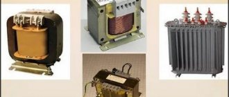
Transformer welding machines are relatively inexpensive and easy to repair due to their simple design. However, they are heavy and sensitive to supply voltage (U). When U is low, it is impossible to carry out work, since significant changes in U occur, as a result of which household appliances may fail. In the private sector, there are often problems with power lines, since in the former CIS countries most power lines require cable replacement.
The electrical cable consists of twists, which often oxidize. As a result of this oxidation, an increase in the resistance (R) of this twist occurs. Under significant load, they heat up, and this can lead to overload of power lines and transformer substation. If you connect an old-style welding machine to an electricity meter, then when U is low, the protection will be triggered (“knock out” the machines). Some people try to connect the welder to the electricity meter, breaking the law.
Such a violation is punishable by a fine: electricity is consumed illegally and in large quantities. In order to make work more comfortable - not to depend on U, not to lift heavy objects, not to overload power lines and not to break the law - you need to use an inverter-type welding machine.
Welding transformer design
Such a device includes several components that create an electric arc capable of melting steel. The components change the parameters of the currents coming from the network.
The unit lowers the voltage, increasing the amperage.
Welding of metals becomes possible thanks to the components included in the design of the device:
- magnetic circuit;
- primary winding of insulated cable;
- screw;
- moving secondary winding made of bare wire;
- running nut;
- handle that rotates the screw;
- clamps for fixing cables;
- cooling system.
We recommend reading: How to install a hood above a welding table
The magnetic circuit does not affect the current parameters, it only forms a magnetic field. For this, a set of steel plates coated with an oxide composition is used. Some transformers include additional components that improve the performance of the equipment.
AC welding transformer device
To make it easier to understand the structure of this product, you can consider everything using the example of such a product as the TDM welding transformer.
AC welding transformer device
- The primary winding is made of insulated wire. It is this that receives the primary current that comes from the network.
- The secondary winding, as a rule, has no insulation on it. Air channels are created on it, which help the better cooling process of this element;
- The moving component of a closed magnetic circuit (also known as the core of a transformer);
- The device suspension system, which is located inside the case and is thereby protected from damage;
- A control system that is responsible for the distance between the transformer windings and increasing or decreasing this air gap;
- A moving screw that controls the air gap between the windings;
- Control screw handle.
But this is not the only option. The device of a welding transformer with moving windings is one of the most popular. Despite the similarity, there may be even relatively small differences in the designs that can affect the operating principle of the welding transformer. The welding transformer TD-500, which has the following design, can be considered standard for many enterprises, as well as educational institutions, where such a design is the main educational one:
Design of welding transformer TD-500
- Transformer housing, which protects all internal parts of the device from damage and external influences;
- Magnetic core;
- Lead screw control handle;
- A lead screw that changes the position of the windings, as a result of which the distance between them changes and creates a different amount of air gap;
- A running nut located inside the housing;
- The secondary winding, which is movable and receives a secondary voltage of a converted value;
- The primary winding, which is stationary and the primary voltage corresponding to that coming from the network, comes through it.
Types and classification of devices
Welding units are classified according to the following characteristics:
- Size and weight. The devices can be compact, portable or stationary, moved using wheels or a hoist (suspended lifting device).
- Open circuit voltage of the welding transformer. In different models of devices, this parameter ranges from 48 to 70 V.
- Maximum current strength. For industrial models this parameter reaches 1000 A, for household models – 50-400 A.
- Voltage of current consumption, number of phases. There are single-phase or three-phase types.
- The nature of the presentation. The device can generate current continuously or pulsed.
- Diameter of connected electrodes.
Lecture No. 7. Design and purpose of a welding transformer
4>
For arc welding, both alternating and direct welding current are used. Welding transformers are used as a source of alternating welding current, and welding rectifiers and welding converters are used as a source of constant current.
The welding transformer is used to reduce the network voltage from 220 or 380 V to a safe, but sufficient for easy ignition and stable burning of the electric arc (no more than 80 V), as well as to regulate the strength of the welding current.
Transformer (Fig. 10). has a steel core (magnetic core) and two insulated windings. The winding connected to the network is called primary, and the winding connected to the electrode holder and the workpiece being welded is called secondary. For reliable arc ignition, the secondary voltage of welding transformers must be at least 60–65 V; The voltage during manual welding usually does not exceed 20 - 30 V.
Fig. 10 Welding transformer
At the bottom of the core is the primary winding, consisting of two coils located on two rods . The primary winding coils are fixed motionless. The secondary winding, also consisting of two coils, is located at a considerable distance from the primary. The coils of both the primary and secondary windings are connected in parallel. The secondary winding is movable and can be moved along the core using a screw with which it is connected and a handle located on the cover of the transformer casing.
The welding current is regulated by changing the distance between the primary and secondary windings . When the handle is rotated clockwise, the secondary winding approaches the primary, the leakage magnetic flux and inductive reactance decrease, and the welding current increases. When the handle is rotated counterclockwise, the secondary winding moves away from the primary, the leakage magnetic flux increases (inductive reactance increases) and the welding current decreases. The limits of regulation of the welding current are 65 - 460 A. The serial connection of the coils of the primary and secondary windings makes it possible to obtain low welding currents with control limits of 40 - 180 A. The current ranges are switched with a handle located on the cover.
The properties of the power source are determined by its external characteristic, which represents the curve of the relationship between the current (I) in the circuit and the voltage (U) at the terminals of the power source.
The power source may have an external characteristic:
rising, hard, falling
The power source for manual arc welding has a falling volt-ampere characteristic.
Open circuit voltage of the power source - the voltage at the output terminals when the cooking circuit is open.
Rated welding current and voltage - the current and voltage for which a normally operating source is designed.
The welding arc power source - welding transformer is designated as follows: TDM - 317
T – transformer
D – for arc welding
M – mechanical regulation
31 – rated current 310 A
7 – model
4>
Date added: 2016-10-26; views: 8840; ORDER A WORK WRITING
Find out more:
The principle of working with characteristics
Devices for transformer welding function as follows:
- Current from the electrical network enters the primary winding. Here a magnetic flux appears, directed towards the core.
- The voltage is transmitted to the secondary winding.
- The ferromagnetic core generates a magnetic field. Electromotive forces of a variable nature are generated in 2 windings.
- The difference in the number of turns of the coils helps to change the current parameters to the volt-ampere indicators necessary for welding. Based on these values, the characteristics of the transformer unit are calculated.
The number of turns of the winding is directly related to the output voltage. A secondary coil wound in larger quantities increases the current strength. A transformer welding machine is a step-down device. The number of turns of the primary winding in it is greater than the secondary. You can regulate the output current by changing the gap between the coils.
Idling
The operating principle of the welding transformer includes 2 modes: idle and with load. During welding, the secondary coil creates a short circuit between the workpiece and the electrode. A powerful arc melts the material, forming a seam. After welding is completed, the secondary circuit is broken. The device starts to idle.
We recommend reading: What types of welding devices are there?
This mode of operation must be safe for the user. The maximum voltage value is 48 V. If the value exceeds the permissible values, the automatic limiter is activated. Grounding the unit body provides additional protection for the welder from electric shock.
How to configure the inverter
Assembling a welding inverter does not require much effort if you have the necessary tools and materials. The costs of a handmade product are minimal due to the use of inexpensive products.
Setting up the device to work properly often requires professional help, but it can be done yourself if you follow the requirements.
- The voltage is supplied to the inverter board, the cooling fan first. This approach will prevent overheating of the system and early failure.
- A short time is allotted for charging the power capacitors, after which the resistor is closed in the circuit. The relay is tested at the output of the resistor; the voltage must correspond to zero. A current-limiting resistor is necessary for the safe use of the inverter; without its use, the device may catch fire.
- An oscilloscope measures the incoming current pulses to the transformer, the ratio should be 66 to 44 percent.
- The welding process with a home-made inverter is checked with a voltmeter connected to the optocoupler at the output of its amplifier.
- A voltage of 16 volts is supplied to the output bridge; a suitable power supply is used for this. When idling, the current consumption is about 100 mA.
The check is carried out with short-term welding processes. When performing welding for up to 10 seconds, it is necessary to control the temperature of the inverter; if the transformers are not very hot, it is possible to gradually increase the operating mode.
Checking inverter connections with a multimeter
Using a home-made welding inverter means the device will fail. To diagnose, you need to open the device case with your own hands and check the voltage at the input. A common problem is the failure of the power supply due to insufficient cooling or poor quality materials used during prolonged operation. You should also visually inspect the connections and check them with a multimeter. If the temperature sensor or fuses fail, they must be replaced with new ones.
Modification schemes
Changes are often made to the design of a standard device to help improve performance.
With shunt
The dissipation of the magnetic field is facilitated by a change in the spatial position of the components of the magnetic circuit.
When steel elements are displaced, the resistance of the flow through the air increases.
When the shunt is fully inserted, the parameter begins to depend on the distance between the part and the components of the magnetic circuit. Devices with this principle of operation are intended for use in industrial environments.
With winding in sections
This welding machine design is considered obsolete. Previously, this equipment was used in domestic and industrial settings. There are several options for choosing the number of turns in the primary and secondary windings.
Thyristor devices
To change the voltage and current, a phase shift of thyristors is used. When assembling a single-phase device, 2 parts are used, installed opposite each other. Thyristors are adjusted symmetrically and synchronously.
In semiconductor transformers, these elements are placed on the primary winding, which is explained by the following reasons:
- The strength of the secondary current in such devices is higher than in thyristors.
- When installing the latter on the primary coil, the efficiency increases. This is due to the reduction in voltage losses.
Advantages and disadvantages
The positive qualities of transformer equipment include:
- High efficiency, ease of operation and maintenance. Repairing the device does not involve large expenses, which allows it to be used at home.
- Low cost.
The disadvantages include:
- Arc instability. This is due to the AC parameters. To work with such devices, specialized electrodes are used.
- Changes in output voltage, which negatively affect the quality of the weld.
- Inability to use for joining parts made of non-ferrous metals or stainless steel.
- Dimensions and heavy weight, causing difficulties when moving.
We recommend reading Current regulator for a welding machine
Design features and principle of operation
The design of a welding transformer is not particularly complicated. A standard welding apparatus consists of:
- magnetic circuit;
- two windings;
- vertical screw with nut;
- handles;
- clamps for fixing wires;
- metal case.
The principle of operation of a welding transformer is as follows: voltage from the network is supplied to the windings, a magnetic field is formed in them, which, in turn, creates a welding current with the necessary parameters.
Features of choosing a welding transformer
When deciding which device to buy, take into account the following criteria:
- Types of metals to be welded, parameters of future seams. To work with steel, manual equipment with direct or alternating current is sufficient. The operational qualities of the transformer allow you to weld products from any ferrous metals.
- Current strength. In domestic conditions, a unit producing 200 A is sufficient.
- Operating principle. Semi-automatic devices are reliable and easy to use, but they are expensive. When using manual units, the welder will have to independently control all parameters.
- Reliability of the manufacturer.
Transformer diagram and calculation
During the calculation, the following parameters must be determined:
- Operational indicators: type of supply network, adjustment range, actual power, duration of continuous operation.
- Welding electrode dimensions.
- Conditions for continuous operation.
- Device efficiency.
Some of the listed parameters are interrelated, for example, phase and network voltage.
The welding current determines the functionality of the transformer, namely, the thickness of the metal being welded. In addition, with increasing current, the diameter of the wire in the windings, the mass of the unit and its dimensions increase, which is due to the need for more efficient cooling of the windings.
The relationships between the main operational characteristics of welding transformers are given below:
- When the thickness of the workpiece being processed is 1...2 mm, the nominal diameter of the electrode is 1.6 mm, and the recommended current value is no more than 50 A.
- When the thickness of the workpiece is 2...3 mm, the nominal diameter of the electrode is 2...2.5 mm, and the recommended current value is no more than 100 A.
- When the thickness of the workpiece being processed is 3...4 mm, the nominal diameter of the electrode is 3 mm, and the recommended current value is no more than 160 A.
- When the thickness of the workpiece is 4...6 mm, the nominal diameter of the electrode is 4 mm, and the recommended current value is no more than 200 A.
- When the thickness of the workpiece is 6...8 mm, the nominal diameter of the electrode is 5 mm, and the recommended current value is no more than 250 A.
- When the thickness of the workpiece is 10...24 mm, the nominal diameter of the electrode is 6...8 mm, and the recommended current value is no more than 320 A.
- When the thickness of the workpiece is more than 24 mm, the nominal diameter of the electrode is 8...10 mm, and the recommended current value is no more than 630 A.
A more detailed calculation of the parameters of a welding transformer is usually carried out when making the unit with your own hands.
What malfunctions can there be
When working with a welding transformer, the following problems often arise:
- No arcing, cooling fan failure to start. The main reason is a violation of the integrity of the power cable. It is less common to detect damage to other equipment components or activation of overheating protection.
- No welding arc when the fan is running. It is observed when there is a breakdown in communication between the internal components of the system.
- No electric arc when the warning light is on. This problem occurs when the protective mode is triggered.
- Formation of a large amount of splashes. The seam quality remains low. It is worth checking that the wires are connected correctly and changing the polarity.
How to mount the device yourself
The main part of a homemade unit is the core. It is made of transformer steel, which is quite difficult to buy. The resulting structure has the shape of a rectangle with a cross-section of more than 55 cm². When forming the primary and secondary coils, install the adjusting screw. It is used to move the movable winding.
The wire cross-section of the first coil must be more than 5 mm². To assemble the transformer, cables with heat-resistant insulation are used.
The secondary winding is formed from a copper conductor with a cross section of 30 mm². At the last stage, a textolite body is assembled, which serves to protect the welder from electric shock.