A capacitive sensor, as defined by the Great Soviet Encyclopedia, is a measuring transducer that allows non-electrical quantities to be converted into electrical capacitance values. For example, such as pressure, liquid level, mechanical force, humidity, and others. Changes in capacitance turn out to be proportional to fluctuations in the measured quantity, and this correspondence makes it possible to track its behavior.
How does this meter work?
In essence, such a sensor is a capacitor. The operation of the meter and control of parameters are based on determining its characteristics. Therefore, it is quite appropriate to remember what a capacitor is.
About the capacitor, its characteristics
As is known, the capacitance of a capacitor is determined by the formula
С=Ɛ×Ɛ0×S/d
Where:
- Ɛ0—dielectric constant;
- Ɛ is the relative dielectric constant of the medium between the plates;
- d - gap between plates;
- S is the area of the plates.
There are three variables in this formula - the dielectric constant Ɛ, the area S of the capacitor plates and the gap between the plates d. Changing any of them will lead to a change in capacitance, and tracking fluctuations will allow you to monitor the characteristics of the environment or other parameter.
Operating principle of a capacitance meter
The simplest technical solution is to include a measuring sensor in the timing circuit of the generator. Without going into the intricacies of circuit design, we can say that the principle of operation of any capacitive sensor is in one way or another connected with changing the parameters of the generator. This occurs due to fluctuations in the capacitance of the capacitor, which leads to the generation of oscillations of a different frequency.
Thus, by monitoring its value at the output of the meter, it is possible to evaluate changes in the controlled parameter. Of course, in each specific case the circuit design may be different. It will largely depend on the parameter of the capacitor, which is influenced by the external environment.
This may be a change in the gap between the capacitor plates due to their approach or removal. Or when filling the tank with another medium, for example water, the value of the dielectric constant will change. Or the capacitor plates will be positioned differently relative to each other after external influences.
Any such impact will cause a change in the capacitance value of the capacitor, and therefore affect the operation of the circuit. For example, capacitive level sensors monitor the filling level of a tank or hopper. Knowing the relationship between the liquid level and the capacitance of the condenser, you can determine how full the tank is.
Although it should be noted that other methods of processing sensor signals can be used. There are quite a lot of them, the choice of one or another depends on specific conditions. The current level of electronics development makes it possible to obtain a processed signal in the form of a digital code.
Another method for measuring capacitance is using analog-to-digital converters. Microcontrollers can handle this task quite well. In this case, the measuring part of devices based on them is significantly simplified.
Capacitive sensor
The membrane is exposed to the medium being measured and is located opposite one or more fixed plates with a gap. As the membrane moves, the capacitance between the plates changes. Membranes can be metal or ceramic. Capacitive devices consume relatively little current, so they can be used in battery-powered wireless applications. Their inherent ability to measure temperature can often be used to provide an additional measure of the process being measured.
- Hysteresis (causes a “set” of readings to appear for the same pressure value);
- Durability (can withstand many high/low pressure measurement cycles);
- Stability (maintains calibration);
- Protection against electromagnetic interference (immunity to local radio interference);
- Temperature range (operation at extreme temperatures of the measured liquid/ambient);
- Vibration and shock resistance (resistance to vibration, shock, pressure surges, etc.);
- Practical range limits (suitable for the measured pressure);
- Diagnostics of failures (visibility when they occur, the possibility of interruption or contamination of the measured flow);
- Safety (certificate for use in hazardous areas);
- Energy consumption (battery power option);
- Output signal (format, analog/digital);
- Materials of construction (temperature range, corrosion resistance);
- Weight;
- Price.
Some of these indicators are measurable and are indicated in the manufacturers' documentation, others are quite difficult to determine. For example, each sensor in a catalog will have an accuracy or temperature range listed, but stability or durability is much more difficult to quantify in any numerical way to compare different devices. Some of these coefficients are directly related to the converter technology. Others depend on the signal processing electronics or the design of the sensor housing.
Almost all electronic technologies work on the principle of measuring the movement of a membrane caused by pressure on one side. Differential pressure sensors have two membranes or one that moves in both directions. The shape and layout of the membranes varies by manufacturer, as do the methods used to measure displacement.
Capacitive, piezoelectric and strain-resistive technologies are most often used; devices based on resonant frequency, electromechanical, magnetic and others are less often used. Each technology has its own specific advantages and limitations.
What types of sensors are there?
All meters based on a capacitive sensor can be divided into:
- single-capacity;
- two-capacity.
It should be noted that the design of capacitive sensors can be:
- flat;
- cylindrical;
- rotary.
The scope of application of any of them is quite extensive. As an example, according to their functional purpose they can be used in the role:
- level meters;
- angular movement monitoring devices;
- motion sensors;
- inclinometers;
- pressure sensors.
These examples do not exhaust the options for using capacitance meters. Other opportunities provided by these devices will be discussed below.
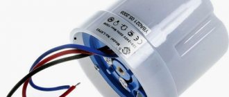
Single capacitive sensors
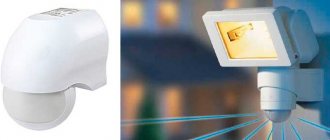
These are the simplest sensors. In fact, they are ordinary capacitors of variable capacitance, changes in which are monitored by a special circuit. Capacitance meters of this type are subject to strong influence from the external environment. It is best to use them to implement various non-contact control options, for example, the approach of unauthorized persons to the protected area or movement in it.
What such capacitors look like in practice can be understood from the figures below.
Dual capacitance sensors
Allows you to reduce the influence of the external environment. A capacitive sensor of this type is characterized by greater measurement accuracy due to the fact that one capacitor serves as a reference. This allows you to compensate for outside influence. Two-capacitance sensors are differential and semi-differential. Schematic examples of constructing such devices are shown below.
Another way to increase the sensitivity of a capacitance meter is to use a bridge circuit.
Level sensors
Capacitive level sensors are devices that allow you to monitor the level of liquid or granular substances in a tank or hopper. Of course, the design of the meter options for different substances will be different, but the principle will remain unchanged.
In fact, capacitive level sensors of this type are two capacitors connected in parallel. Only in one the dielectric is air, and in the other it is a liquid or other substance. Thus, the capacity of each of them will be different, it will change and depend on the degree of filling of the bunker (tank).
The given drawing or diagram of a capacitive sensor is distinguished by its simplicity of construction and versatility. However, in order to increase the accuracy of the measurement, it is best to at least additionally control the temperature of the liquid; the value of the dielectric constant depends on it. And depending on the temperature, it will be necessary to use a correction factor in the calculations.
Linear motion sensors
Such devices can be used for a variety of purposes, for example:
- control of the beginning and end of the working stroke of the actuator in automatic machines;
- positioning of various objects;
- recording the appearance of a third-party object in the alarm system;
- like a limit switch.
Sensors of this type can operate on different principles. Below we will consider two options for their implementation.
- Based on changes in the gap between the capacitor plates.
In this embodiment, the impact falls on one of the plates; it can shift under the applied force, which causes a change in the capacitance of the capacitor, proportional to the impact. - In the embodiment presented below, the operation of the sensor is based on a change in the dielectric constant of the dielectric between the plates.
Angle sensors
At their core, such sensors are similar to linear displacement sensors, and most often devices with variable area are used for these purposes. One of the capacitor plates is attached to the object's shaft, while the other remains stationary. Changing the degree of plate overlap causes capacitance fluctuations.
To increase measurement accuracy, multi-section transducers are most often used.
Inclinometer
The operating principle of such a device is similar to how a capacitive level sensor works. A substrate is attached to a special capsule, on which two isolated sections are located, which are one of the terminals of the capacitor. Inside the capsule is filled with a conductive liquid. It is the other electrode of the capacitor. Its capacity is determined by the vertical position of the device and does not depend on the angle of inclination in other directions.
Pressure meter
In such a meter, pressure causes a change in the distance between the capacitor plates. This is achieved by the fact that between its plates there is an elastic membrane, which is affected. The partition, depending on the pressure, moves in one direction or another, which leads to a change in capacity.
Operating principle
The operating principle of capacitive detectors is based on recording changes in the capacity of the protected object to which they are connected. A change in capacitance leads to a change in the frequency of the generator; a decrease in this frequency below a certain threshold leads to the formation of an “Alarm” signal. The sensitivity of these detectors is estimated by the distance to the antenna, usually 10-30 cm.
Considering that such detectors are sensitive to electromagnetic interference, and there is a lot of it in the modern world, it is necessary to use complex algorithms for processing the received signals in order to filter out all the resulting interference and interference.
Capacitive touch sensors
Considering various types of sensors based on electrical capacitance, one cannot ignore their use as touch sensors. The most obvious example of such devices are smartphones. Implementing touch sensors can be quite complex, but it is based on some simple fundamental principles. The operation of such devices is based on:
- on using your own capacity;
- on the use of mutual capacitance.
Next, we will consider the principle of operation of touch sensors based on their own capacitance.
Self-capacitance based sensor
The capacitor exists not only in the form of a separate volumetric element with leads. Capacitance is also possessed by two ordinary conductors located in parallel. Based on this, it is possible to obtain a capacitor based on electrically conductive layers separated by some kind of dielectric. Such a capacitor can be obtained on the basis of a printed circuit board.
It is presented in the figure below (in two projections - top and side). We see a separate area (touch button), separated from the general layer of copper. And since the remaining areas are connected to the ground, the sensor pad can be represented as a capacitor between it and the ground.
The capacitance of such a capacitor will be small, about 10 pF. But for various devices its significance is not fundamental. When monitoring, it is often not the capacity that is important, but its change. This is exactly what the circuits that process the state of the touch button are designed for.
How to change the state of a button
The simplest thing you can do is touch with your finger. It should be immediately noted that such a touch does not pose any danger to humans. Typically, all boards are varnished so that there is no direct contact with conductive elements. However, there will be changes in the state of the capacitor. This is possible for two reasons:
- due to the dielectric constant of the human body;
- due to its own conductivity
The body has its own dielectric constant
Due to the fact that the dielectric constant of the body differs from the dielectric constant of the air, which serves as an insulator at the initial moment, the capacitance of the capacitor will change. Here the calculation is simple - the dielectric constant of air is 1, and water is 80 (the human body is mostly made of water). This means that the capacity of the touch button will increase.
You don't even have to touch it to make this change. As scientists' studies have shown, sometimes it's enough just to bring your finger to the contact.
The body has its own conductivity
This is a long established fact.
And although it was said above that touch does not pose a danger to humans, nevertheless, it contributes to changing the state of the touch button. Simply put, we can assume that the finger capacitance is connected parallel to the touch button capacitance. Therefore, the total capacity of the system, as in the previous case, will increase. This means that both mechanisms considered (changes in dielectric constant and the human body’s own conductivity) lead to an increase in capacitance.
Capacitive proximity sensors
Among the wide variety of capacitive designs, it can sometimes be difficult to choose the most suitable capacitive sensor option for a given case. In many publications on the topic of capacitive devices, the scope and distinctive features of the proposed designs are described very briefly and the radio amateur often cannot figure out which capacitive device circuit should be preferred for repetition.
This article provides a description of various types of capacitive sensors, gives their comparative characteristics and recommendations for the most rational practical use of each specific type of capacitive structures.
As is known, capacitive sensors are capable of responding to any objects and, at the same time, their response distance does not depend on such properties of the surface of the approaching object, such as, for example, whether it is warm or cold (unlike infrared sensors), as well as whether it is hard or soft (unlike ultrasonic motion sensors). In addition, capacitive sensors can detect objects through various opaque “obstacles”, for example, building walls, massive fences, doors, etc. Such sensors can be used both for security purposes and for household purposes, for example, to turn on the lighting when entering a room; for automatic door opening; in liquid level alarms, etc. There are several types of capacitive sensors.
1. Sensors on capacitors. In sensors of this type, the response signal is generated using capacitor circuits and similar designs can be divided into several groups. The simplest of them are circuits based on capacitive dividers.
In such devices, for example [1], the antenna-sensor is connected to the output of the working generator through a small capacitance separating capacitor, while at the point of connection of the antenna and the above capacitor, an operating potential is formed, the level of which depends on the capacitance of the antenna, while the antenna is the sensor and the isolation capacitor form a capacitive divider and when any object approaches the antenna, the potential at the point of its connection with the isolation capacitor decreases, which is a signal for the device to operate.
There are also circuits based on RC generators. In these designs, for example [2], to generate a response signal, an RC generator is used, the frequency-setting element of which is a sensor antenna, the capacitance of which changes (increases) when any object approaches it. The signal specified by the capacitance of the sensor antenna is then compared with the reference signal coming from the output of the second (reference) generator.
Sensors on deployed capacitors. In similar devices, for example [3], two flat metal plates placed in the same plane are used as an antenna-sensor. These plates are the plates of an unfolded capacitor and when any objects approach, the dielectric constant of the medium between the plates changes and, accordingly, the capacitance of the above capacitor increases, which is a signal to trigger the sensor. There are also known devices, for example [4], which use a method of comparing the antenna capacitance with the capacitance of a standard (reference) capacitor (Rospatent link).
At the same time, a characteristic feature of capacitive sensors on capacitors is their low noise immunity - the inputs of such devices do not contain elements that can effectively suppress extraneous influences. Various pickups and radio interference received by the antenna create a large amount of noise and interference at the input of the device, making such designs insensitive to weak signals. For this reason, the object detection range of capacitor-based sensors is small; for example, they detect the approach of a person from a distance not exceeding 10 - 15 cm. However, such devices can be very simple in design (for example [1]) and in There is no need to use winding parts - coils, circuits, etc., due to which these designs are quite convenient and technologically advanced to manufacture.
Scope of application of capacitive sensors on capacitors. These devices can be used where high sensitivity and noise immunity are not required, for example in metal contact detectors. objects, liquid level sensors, etc., as well as for beginner radio amateurs getting acquainted with capacitive technology.
2. Capacitive sensors on the frequency-setting LC circuit. Devices of this type are less susceptible to radio interference and interference compared to capacitor-based sensors. The sensor antenna (usually a metal plate) is connected (either directly or through a capacitor with a capacity of several tens of pF) to the frequency-setting LC circuit of the RF generator. When any object approaches, the capacitance of the antenna changes (increases) and, accordingly, the capacitance of the LC circuit. As a result, the frequency of the generator changes (decreases) and operation occurs.
Features of capacitive sensors of this type. 1) The LC circuit with the antenna-sensor attached to it is part of the generator, as a result of which interference and radio interference affecting the antenna also affect its operation: through positive feedback elements, interference signals (especially pulsed ones) leak to the input of the active element of the generator and are amplified in it, forming extraneous noise at the output of the device, reducing the sensitivity of the structure to weak signals and creating the danger of false alarms. 2) The LC circuit, operating as a frequency-setting element of the generator, is heavily loaded and has a reduced quality factor, as a result of which the selective properties of the circuit are reduced and its ability to change its tuning when the antenna capacitance changes is deteriorated, which further reduces the sensitivity of the design. The above-mentioned features of sensors on the frequency-setting LC circuit limit their noise immunity and object detection range; for example, the human detection distance with sensors of this type is usually 20 - 30 cm.
There are several varieties and modifications of capacitive sensors with a frequency-setting LC circuit.
1) Sensors with a quartz resonator. In such devices, for example [5], in order to increase the sensitivity and stability of the generator frequency, the following are introduced: a quartz resonator and a differential RF transformer, the primary winding of which is an element of the frequency-setting circuit of the generator, and its two secondary (identical) windings are elements of the measuring bridge, to which an antenna-sensor is connected, connected in series with a quartz resonator, and when any object approaches the antenna, a response signal is generated. The sensitivity of such designs is higher compared to conventional sensors on a frequency-setting LC circuit, however, they require the manufacture of a differential HF transformer (in the above design [5], its windings are placed on a ring of standard size K10 × 6 × 2 made of M3000NM ferrite, while to increase the quality factor, a gap 0.9...1.1 mm wide is cut in the ring.
2) Sensors with a suction LC circuit. These designs, for example [6], are capacitive devices into which, in order to increase sensitivity, an additional (called a suction) LC circuit is introduced, inductively coupled to the frequency-setting circuit of the generator and tuned into resonance with this circuit. The sensor antenna, in this case, is connected not to the frequency-setting circuit, but to the above-mentioned suction LC circuit, which includes a low-capacity capacitor and a solenoid, the inductance of which is, accordingly, increased. Because The loop capacitor, in this case, should be small - at the level of M33 - M75. Due to the small capacitance of this circuit, the capacitance of the sensor antenna becomes comparable to it, due to which changes in the antenna capacitance have a significant impact on the setting of the above suction LC circuit, while the amplitude of oscillations in the frequency-setting circuit of the generator and , respectively, is the level of the RF signal at its output.
It can also be noted that in such designs the connection between the antenna and the frequency-setting circuit of the generator is not direct, but inductive, due to which weather and climatic influences on the antenna cannot have a direct effect on the operation of the active element of the generator (transistor or op-amp), which is positive properties of such structures. As in the case of sensors based on a quartz resonator, increasing the sensitivity of capacitive devices with a suction LC circuit is achieved due to some complication of the design - in this case, the manufacture of an additional LC circuit is required, including an inductor with a number of turns twice as large (in [6] - 100 turns) compared to the coil of the frequency-setting LC circuit.
3) Some capacitive sensors use a method such as increasing the size of the sensor antenna . At the same time, such structures also increase their susceptibility to electromagnetic interference and radio interference; For this reason, as well as due to the bulkiness of such devices (for example, in [7] a metal mesh measuring 0.5 × 0.5 M is used as an antenna), it is advisable to use these designs outside the city - in places with weak electromagnetic background and, preferably, outside residential premises so that there is no interference from network wires. Devices with large sensor sizes are best used in rural areas to protect garden plots and field objects. Scope of application of sensors with a frequency-setting LC circuit. Such devices can be used for various household purposes (turning on lights, etc.), as well as for detecting any objects in places with a quiet electromagnetic environment, for example, in basements (located below ground level), as well as outside the city (in rural areas - in the absence of radio interference - sensors of this type can detect, for example, the approach of a person at a distance of up to several tens of cm). In urban conditions, it is advisable to use these designs either as sensors for touching metal objects, or as part of those alarm devices that, in the event of false alarms, do not cause great inconvenience to others, for example, in devices that include a deterrent light flux and a low sound signal.
3. Differential capacitive sensors (devices on differential transformers). Such sensors, for example [8], differ from the designs described above in that they have not one, but two sensor antennas, which allows for suppression (mutual compensation) of weather and climatic influences (temperature, humidity, snow, frost, rain, etc. .). In this case, to detect the approach of objects to any of the antennas of the capacitive device, a symmetrical measuring LC bridge is used, which responds to changes in capacitance between the common wire and the antenna.
These devices work as follows. The sensitive elements of the sensor - antennas - are connected to the measuring inputs of the LC bridge, and the RF voltage required to power the bridge is formed in a differential transformer, the primary winding of which is supplied with a supply RF signal from the output of the RF generator (in [8] - in For the sake of simplicity, the coil of the frequency-setting circuit of the generator is also the primary winding of the differential transformer). The differential design transformer contains two identical secondary windings, at opposite ends of which an anti-phase alternating RF voltage is generated to power the LC bridge. In this case, at the output of the bridge, there is no RF voltage because the RF signals at its output will be equal in amplitude and opposite in sign, due to which their mutual compensation and suppression will occur (in the measuring LC bridge, the operating currents go towards each other each other and are mutually compensated at the output). In its initial state, there is no signal at the output of the measuring LC bridge; if an object approaches any of the antennas, the capacitance of one or another arm of the measuring bridge increases, causing an imbalance in its balancing, as a result of which the mutual compensation of the RF signals of the generator becomes incomplete and a signal to trigger the device appears at the output of the LC bridge.
Moreover, if the capacitance increases (or decreases) for both antennas at once, then operation does not occur because in this case, the balancing of the LC bridge is not disrupted and the RF signals flowing in the LC bridge circuit still retain the same amplitude and opposite signs.
Thanks to the above property, devices based on differential transformers, as well as the differential capacitor sensors described above, are resistant to weather and climatic fluctuations because they affect both antennas equally and then cancel each other out and are suppressed. In this case, interference and radio interference are not suppressed, only weather and climatic influences are eliminated, therefore, differential sensors, like sensors on the frequency-setting LC circuit, periodically experience false alarms. The antennas should be positioned so that when an object approaches, the impact on one of them would be greater than on the other.
Features of differential sensors. The detection range of these devices is slightly higher compared to sensors on a frequency-setting LC circuit, but differential sensors are more complex in design and have increased current consumption due to losses in the transformer, which has limited efficiency. In addition, such devices have a zone of reduced sensitivity between the antennas.
Application area . Sensors on a differential transformer are intended for use in outdoor conditions. These devices can be used in the same place as sensors on the frequency-setting LC circuit, with the only difference being that to install a differential sensor, space is required for a second antenna.
4. Resonant capacitive sensors (RF patent No. 2419159; link Rospatent). Highly sensitive capacitive devices - the response signal in these designs is generated in the input LC circuit, which is in a partially detuned state with respect to the signal from the working RF generator, to which the circuit is connected through a small capacitor (a necessary resistance element in the circuit). The operating principle of such structures has two components: the first is an appropriately configured LC circuit, and the second is a resistance element through which the LC circuit is connected to the output of the generator.
Due to the fact that the LC circuit is in a state of partial resonance (at the slope of the characteristic), its resistance in the RF signal circuit strongly depends on the capacitance - both its own and the capacitance of the sensor antenna attached to it. As a result, when any object approaches the antenna, the RF voltage on the LC circuit significantly changes its amplitude, which is a signal to trigger the device.
At the same time, the LC circuit does not lose its selective properties and effectively suppresses (shunts to the housing) extraneous influences coming from the antenna-sensor - interference and radio interference, ensuring a high level of noise immunity of the design.
In resonant capacitive sensors, the operating signal from the output of the RF generator must be supplied to the LC circuit through some resistance, the value of which must be comparable to the resistance of the LC circuit at the operating frequency, otherwise, when objects approach the sensor antenna, the operating voltage The LC circuit will respond very weakly to changes in the resistance of the LC circuit in the circuit (the RF voltage of the circuit will simply repeat the output voltage of the generator).
It may seem that an LC circuit that is in a state of partial resonance will be unstable and overly affected by temperature changes. In reality, provided that you use a loop capacitor with a small value, i.e. (M33 - M75) - the circuit is quite stable, including when the capacitive device is operating in outdoor conditions. For example, when the temperature changes from +25 to -12 degrees. The RF voltage on the LC circuit changes by no more than 6%.
In addition, in resonant capacitive designs, the antenna is connected to the LC circuit through a small capacitor (there is no need to use strong coupling in such devices), due to which weather influences on the sensor antenna do not disrupt the operation of the LC circuit and its operating RF voltage remains practically unchanged even in rain. In terms of their range, resonant capacitive sensors are significantly (sometimes several times) superior to devices based on frequency-setting LC circuits and differential transformers, detecting the approach of a person at a distance significantly exceeding 1 meter.
With all this, highly sensitive designs using the resonant principle of operation have appeared only recently - the first publication on this topic is the article “Capacitive relay” (magazine “Radio” 2010 / 5, pp. 38, 39); in addition, additional information about resonant capacitive devices and their modifications is also available on the website of the author of the above article: https://sv6502.narod.ru/index.html.
Features of resonant capacitive sensors . 1) When manufacturing a resonant sensor intended for operation in outdoor conditions, a mandatory check of the input node for thermal stability is required, for which the potential at the output of the detector is measured at different temperatures (for this you can use a refrigerator freezer), the detector must be thermally stable ( on a field-effect transistor). 2) In resonant capacitive sensors, the connection between the antenna and the RF generator is weak and therefore the emission of radio interference into the air for such designs is very insignificant - several times less compared to other types of capacitive devices.
Application area . Resonant capacitive sensors can be effectively used not only in rural and field, but also in urban conditions, while refraining from placing sensors near powerful sources of radio signals (radio stations, television centers, etc.), otherwise resonant capacitive devices will also exhibit false triggering. Resonant sensors can also be installed in close proximity to other electronic devices - due to the low level of radio signal emission and high noise immunity, resonant capacitive designs have increased electromagnetic compatibility with other devices.
Links
[1] Nechaev I. "Capacitive relay", journal. "Radio" 1988 /1, p.33. [2] Ershov M. "Capacitive sensor", journal. “Radio” 2004 / 3, pp. 41, 42. [3] Moskvin A. "Non-contact capacitive sensors", journal. “Radio” 2002 / 10, pp. 38, 39. [4] Galkov A., Khomutov O., Yakunin A. “Capacitive adaptive security system” RF patent No. 2297671 (C2), with priority dated June 23, 2005 – Bulletin “Inventions. Useful models", 2007, No. 11. [5] Savchenko V, Gribova L. "Non-contact capacitive sensor with a quartz resonator", zhur. “Radio” 2010 / 11, pp. 27, 28. [6] “Capacitive relay” - journal. "Radio" 1967 / 9, p. 61 (section of foreign designs). [7] Rubtsov V. “Security alarm device,” journal. “Radio Amateur” 1992 / 8, p. 26. [8] Gluzman I. "Presence relay", journal. "Modelist-constructor" 1981 / 1, pp. 41, 42).
Author: Solomein Vladislav Petrovich, Ekaterinburg, 620016, P.O. Box No. 97. E-mail
Presence sensors
Another equally important and popular application for capacitance-based sensors is their use to detect someone or something in the control area. The simplest example is turning on the lighting on the landing. Although this far from exhausts the capabilities of such meters. The use of such sensors in security alarm systems is no less in demand. Or counting the number of piece products.
How it works
It was already noted above that the human body has a certain dielectric constant and conductivity.
The figure shows a schematic representation of such a system. There are two electrodes connected to the meter. Each of them has its own capacity, designated C1. As a result, the entire system has a certain resulting capacity.
When a new object, for example a person, appears in the controlled area, the system forms two additional capacitances: Ca - between the electrode and the human body, and Cb - between the person and the ground. The resulting capacity of the entire system will change, and this change can be monitored by the monitoring circuit.
Another way to detect presence
In this case, the effect of increasing the capacity when a foreign object appears in the control zone is also used. Only in this case is the mechanism of active influence on the controlled area applied. For this, a sensor circuit with an active emitter is used.
Such a meter includes a signal generator, a comparator and an amplifier-converter. When the circuit is turned on, an electric field appears in the space in front of the meter. The generator is configured in such a way that it will not start if there are no foreign objects. This is achieved by the fact that the free space is considered to be an unfolded capacitor with a dielectric constant equal to 1. The capacitance value is insufficient to start the generator.
When any materials, objects, or people appear in front of the meter, the dielectric constant of the medium changes (increases), and the capacitance of the capacitor also increases. This causes the generator to start. The amplitude of the vibrations will depend on the distance to the object, its material and dielectric constant.
When the oscillation amplitude reaches a certain value, the comparator is triggered and outputs a signal to the amplifier. Foreign object detected.
This scheme can be used not only in security alarm systems to detect intrusion into a closed area, but also for other purposes. A system for counting the quantity of piece goods, for example, milk packages, cans or any other similar items, can work on this principle.
Piezoelectric sensors
This technology is very diverse and different design options are possible, so it is not so easy to characterize it exactly. The diaphragm exerts pressure on the crystal, which either generates an electrical charge (piezoelectric effect) or changes resistance (piezoresistive effect) depending on the degree of deflection or pressure on the crystal. The membrane can contact the crystal directly or transmit pressure hydraulically through silicone oil. Sensors based on this technology come in a variety of sizes and configurations. Although they do not achieve the accuracy of capacitive sensors, these devices have a wider operating temperature and pressure range. Membranes can be metal or ceramic. They are also sensitive to temperature and usually have the ability to measure it in order to subsequently correct the measurement results. Temperature can often be used as an additional process variable.
Possible applications of the sensors
The considered capacitive sensors for level, pressure, position and other types of similar products, as well as design features, allow us to draw a conclusion about their versatility. This means they can be used in different areas of industry, regulation and control schemes. As an example, we can name the following areas of the national economy where such meters can be used:
- Oil and gas industry;
- metal mining and processing;
- mining industry;
- agriculture, including livestock and crop production;
- wood processing industry;
- beverage and food production;
- machine tool building and robotic complexes;
- pulp and paper industry;
- chemical industry and others.
The use of capacitive converters allows you to solve a variety of problems. It is simply unrealistic to list them all, but again, as examples, we can list the following options for their use:
- indication of the position of liquids, bulk substances, including products, in a pipe or storage facility, control of their filling;
- alarm for broken wire, tape, or other similar items during winding;
- counting the number of piece products;
- belt tension control;
- use in security systems to detect unauthorized intrusion.
Benefits of capacitive sensors
Among the undoubted advantages of such sensors, wherever they are used, be it in Moscow or Antarctica, it is worth noting:
- light weight, dimensions, low power consumption;
- lack of contacts;
- long service life;
- the ability to adapt sensors for use to solve various problems;
- little effort required to move moving parts.
- ease of manufacture, as well as the use of accessible, inexpensive materials for these purposes;
Main advantages of capacitive sensors
It should be noted that the capacitive sensor has many advantages when compared with similar devices that are made according to slightly different principles. Let's list the main advantages of these instrumentation systems:
- They are extremely simple to make. In addition, the simplest and cheapest materials can be used in their production. Even capacitive fuel level sensors used at important oil industry facilities have extremely modest dimensions and have the lowest possible level of electrical energy consumption. With all these characteristics, they are distinguished by an excellent level of sensitivity, which is often unattainable even for more expensive devices.
- In principle, you can make a capacitive sensor with your own hands, using any more or less reliable and high-quality industrial capacitor as its basis.
- They do not have contacts (one current collector is very rarely used), which has an extremely beneficial effect on working in conditions of high dust and humidity in the room.
- The service life is extremely long; the device manages to “recoup” its low cost many times over. Accordingly, a capacitive sensor (the price of which is in the range of 1200-1700 rubles) is an extremely profitable purchase.
- Surprisingly little effort is required to move the moving part of the device.
- The device is very easily combined with almost all categories of equipment that is used in industrial activities.
Where can I buy
Various touch devices can be purchased at a specialty store. But there is another option that has recently received significant improvements. You no longer need to wait a long time for a parcel from China: the AliExpress online store now offers the opportunity to ship from transshipment warehouses located in various countries. For example, when ordering, you can specify the “Delivery from the Russian Federation” option.
Follow the links and choose:
| Capacitive soil moisture sensor | Capacitive touch switch, spring switch | Capacitive touch button |
| High Quality LJC18A3-HZ/BX 1-10mm Capacitive Proximity Sensor | LJC18A3-HZ/BX 1-10mm capacitive proximity sensor | Capacitive Touch DC Switch Button |