What is a modular contactor and what is it for?
According to its functional purpose, the modular contactor KM belongs to the switching equipment for remote control of powerful loads operating at direct or alternating current.
They break current circuits in several places at once, and this differs from electromagnetic relays, which break the circuit at only one point. Quite often, modular contactors work in conjunction with auxiliary devices - set-top boxes, thermal relays, blocking devices and other modular devices. As a result of such combinations, equipment is obtained that has special properties and is capable of performing specified functions. So, when installing a delay module, you get a contactor with a delay function, and a thermal overload relay transfers the contactor to the category of a magnetic starter.
With the help of auxiliary elements, the capabilities of the main devices are significantly expanded, their performance characteristics are improved, and installation is simplified.
At their core, contactor devices are considered modified versions of a starter, which additionally contains a thermal relay and a contact group for starting the electric motor. Low voltage electromagnetic starters, reversible and non-reversible. The first option includes two identical contactors, with the same rated current. It has a mechanical or electrical interlock that prevents the main contacts from closing at the same time.
The protective functions in these devices are performed by electrothermal current relays and other similar devices. Low power electrical contactor, used as an intermediate relay. It is designed for low-current circuits and has a large number of switchings. Using this device, it is possible to connect many additional sections and control their on/off.
Description of the device, its purpose
A modular contactor (MC) is a compact electromagnetic device designed for switching DC and AC power circuits in normal modes. This means that the device does not protect equipment from short circuits, voltage surges and other network changes, as well as operational overloads.
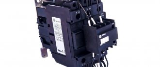
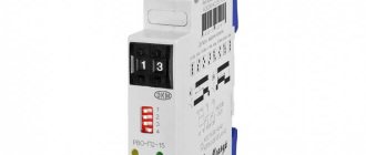
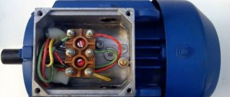
Appearance of modular contactors from different manufacturers
The outline, shape of the device, its dimensions and the presence of DIN rail mounting allow it to ergonomically fit into the electrical panel next to other automation and protection devices (circuit breakers, phase control relays, etc.).
The devices are capable of operating in networks with voltages up to 660 Volts and rated currents up to 100 Amperes.
Design and principle of operation
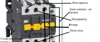
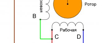
A standard contactor design includes several basic parts. The device consists of a housing (1), a control coil output terminal (2), a power contact terminal (3), a fixed magnetic core (4), a moving part - a core (5), a control coil (6), a short-circuited magnetic circuit ring (7), fixed and moving contacts (8 and 9), on-off indicator lever (10).
The coil is the main element that creates the magnetic current. If it is also used as a throttle, then with its help a driving force is generated that ensures the operation of the devices. The tension of the contacts is fixed using a contact spring. During docking, the moving and fixed contacts are connected to each other. They are constantly in motion and perform certain actions. Fixed contacts are fixed to the body, and movable contacts are connected to the core.
The contactor works as follows:
- After applying voltage to the control coil, the armature is attracted to the core. As a result, the contact group closes or opens, in accordance with the initial position of a particular contact.
- After turning off the power, all actions occur in the reverse order. The electric arc that occurs at the moment of opening is extinguished using an arc extinguishing system.
- After the voltage supply is stopped, the electromagnetic field disappears and ceases to hold the armature or core.
- The return spring moves the contacts to their original position, completely opening the circuit. Thus, the modular contactor performs its main work during periods of supply and shutdown of voltage.
Basic Concepts
A modular contactor is a special electrical device that can control the flow of current in a specific circuit. Very often, such systems are used to organize the operation of heating pumps or heated floors. The contactor consists of several main parts:
- coil. It consists of many copper wires connected into a single circuit. Its main purpose is to create an electromagnetic field;
- contact elements. These structures are metal plates that are pressed by springs. In the initial position, the system is in an open state.
The operating principle of the contactor is quite simple. When current is applied to the coil, it begins to produce a magnetic field. It, in turn, attracts the plates that close the circuit. Thus, the current that is needed for the operation of certain mechanisms is supplied to the system. When the electricity supply stops, the magnetic field disappears and the plates are pressed back, breaking the circuit.
Classification of contactor devices
There are different types of contactors, differing from each other in various respects. Among them, the following parameters can be distinguished.
First of all, they are classified according to their purpose. This includes the following types and categories:
- Devices for remote switching. Most of them operate under manual operator control using buttons or switches. At the right time, a signal is given and the device is activated. In another method, several contactors are connected into a common automated power system that uses electronic circuitry to issue commands. In case of an emergency, a protection system is provided that opens the contacts.
- Switching on powerful electrical equipment using low-current lines. The question arises, why is a contactor needed in such cases? Wouldn't it be better to use a traditional button? This, of course, can be done, but then you will need very massive and bulky equipment, and the switching process itself will require significant effort. The same goes for turning it off. Therefore, compact low-current devices are used for these purposes, allowing for high-frequency on-off cycles. Thus, a weak current is supplied to the coil, and only then the powerful electric motor is started.
Each modular contactor is divided according to the type of drive it operates. In this case, you can also note various options:
- The electromagnetic drive is considered the main one; it is the principle behind the operation of most devices. When voltage is applied, the device turns on, and when there is no voltage, the device turns off. After a complete shutdown, it must be turned on again, which provides additional safety when working with electrical installations.
- The contact group can be driven using pneumatic devices. Such a system, designed for switching, does not require an electromagnetic drive. The control command is supplied by a high pressure pulse. Similar systems are used for railway locomotives and other pneumatic installations.
Any modular contactor KM, depending on the modification, can be mounted in different ways:
- Specialized devices, including those without housings, do not have any design restrictions and are installed solely from the standpoint of normal functionality and safe operation.
- There are designs created individually for a specific electrical installation. They are not suitable for domestic use as they are placed in specially designated areas.
- During standard installation, the modular contactor and its connection are carried out on a DIN rail in the panel, together with other devices.
There are also differences according to the rated voltage of the main circuit. In this case, the KM contactor can be part of a group of devices operating with voltages of 220 and 440 volts or in a group with voltages of 380 and 660 V. The device can be single-pole, as well as double-pole and with a large number of poles - up to 5 units.
Connection diagrams for consumers and modular contactors
In accordance with the type of electrical equipment used, in each case an individual connection diagram for the modular contactor is provided. The most widespread is the standard version, which uses only one device, as well as reversible circuits and with the connection of single-phase consumers. Each of them should be considered in more detail.
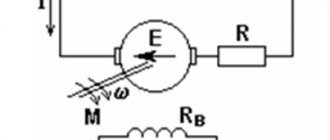
The most popular scheme is connecting a three-phase electric motor through a modular contactor KM (Fig. 1). The usual START and STOP buttons are used for control. Overload protection is provided using a thermal relay. In case of short circuits, the electrical circuit is equipped with an automatic switch.
Another circuit is reversible (Fig. 2), used when connecting a modular contactor to an electric motor so that the reverse function appears. It is constantly needed in various lifting mechanisms, machines and other equipment. In this case, another switching device is connected. It is involved in changing the locations of two phases, which also leads to a change in the direction of rotation of the shaft. This circuit is also supplemented with protective equipment - a thermal relay and a circuit breaker.
The main purpose of contactors in the third circuit is to work with single-phase consumers. As a rule, these are lighting systems, electric pumps and other equipment operating with a single phase.
Schemes for connecting a consumer via modular contactors
Depending on the type of equipment, there are several options for switching using the device in question. The most used are:
- simple circuit using one MK;
- reverse circuit;
- connection diagram for a single-phase consumer.
An example of each circuit is shown in the following images:
A simple diagram for connecting a three-phase motor via MK
In this diagram, control is carried out by the “Start” and “Stop” buttons. The electric motor is protected from overload by a thermal relay. To prevent the destructive effects of short circuit currents, an automatic switch is provided in the circuit.
The following diagram shows the connection of an electric motor with the possibility of reverse (rotation of the shaft in one direction or the other at the choice of the operator). This function is often needed, for example on lifting machines or drilling machines.
There are also protective equipment here - a circuit breaker and a thermal relay. However, instead of one switching device, two are installed. As you know, in order to change the direction of rotation of the motor, it is necessary to swap two phases. This function is performed by the second modular contactor, whose phase rotation has been changed.
Reversible circuit for connecting an electric motor using two MKs
The following diagram shows the connection of a single-phase consumer. In this case, it is an electric pump, although it could also be a lighting network or a convector (the principle does not change).
Connection diagram for a pump from a single-phase network via a modular contactor
Specifications
The main parameters and technical characteristics are applied to the body of the device, including the ABB contactor. First of all, this is the value of the rated current, the type and number of contacts. Each model and modification has its own indicators.
Most often, switching devices that work with various electrical equipment have the following characteristics:
- The nominal operating voltage of alternating current is 230, 400 and 600 volts.
- The value of the rated operating current, with category of use AC-3, is 12 A.
- Indicators of conditional thermal current with category of use AC-1 – 25 A.
- Rated switching power for voltage 230 V in category AC-3 is 3 kW.
- Rated switching power for voltage 400 V in category AC-3 is 5.5 kW.
- Rated switching power for voltage 660 V in category AC-3 is 7.5 kW.
Separately, it should be noted the characteristics of the control circuits in the contactor itself:
- The nominal voltage of the control coils is 24, 36, 110, 230 and 400 volts.
- When triggered, the coil consumes 60 VA of power.
- In the hold position, the coil consumes power of 7 VA.
- The contacts close within 12-22 milliseconds.
- The contacts open within 4-16 ms.
- The control coil has a dissipation power of 3 W.
Thanks to these indicators, these devices are widely used in electrical, industrial and other fields.
Why are contactors needed? Application area
A contactor (modular contactor, power relay) is a remotely controlled switching device that allows you to switch powerful (including inductive) loads of both alternating and direct current. The main feature of contactors is that they break the current circuit at several points simultaneously, unlike electromagnetic relays, which usually break the circuit at one point. The main areas of application of contactors: control of powerful electric motors, switching of reactive power compensation circuits, etc. – where it is necessary to carry out frequent starts, switching of electrical devices with high load currents. Electromagnetic contactors According to the rated voltage of the main circuit, contactors are divided into 2 groups: with voltage 220, 440V and 380, 660V. Contactors can have from 1 to 5 main poles.
The principle of operation of the contactor is that voltage is applied to the control coil, the armature is attracted to the core and the contact group is closed or opened depending on the initial state of each of the contacts. When disconnected, the opposite occurs. The arcing system of the contactor ensures the extinguishing of the electric arc that occurs when the main contacts open.
You can install auxiliary modules on contactors (contactor attachments, time delay attachments, thermal relays, blocking devices), thereby obtaining different devices. For example, if you install a delay module on a contactor, you will get a contactor with a delay. If we install a mechanical locking mechanism on 2 contactors, we get a reversible contactor. The contactor, together with the thermal overload relay, forms a magnetic starter, etc. Auxiliary modules are used to expand the possibility of using contactors in automation systems, improve the operation of electrical installations, and simplify installation.
A starter is a modified contactor that requires the presence of a thermal relay, an additional contact group or an automatic machine for starting an electric motor. Electromagnetic low-voltage starters are divided into non-reversible (for controlling electric motors with a constant direction of rotation); without switching motor windings; with switching of electric motor windings; reversible (for controlling electric motors with alternating directions of rotation). Reversing starters are made on the basis of two contactors of the same type with the same rated currents, and these starters are equipped with electrical or mechanical interlocking, which eliminates the possibility of simultaneous closing of the main contacts of both contactors. Depending on the presence of an electric motor protection device, starters can be without a protection device, with an electrothermal current relay, or with a temperature protection device.
An intermediate relay is a low-power contactor that serves to multiply contacts in low-current circuits and, unlike a contactor, is designed for a much larger number of switchings. Thus, a contactor and an intermediate relay for the same power with the same contact group have different purposes and, accordingly, uses.
Expect articles on starters and intermediate relays in further reviews.
Description and purpose
These contactors are almost always custom-made, so don’t expect to be lucky and buy them quickly. Each symbol in the name of ABB contactors has a specific meaning.
The voltage can be connected from 12 to V, you must also pay attention to this, since a modular contactor designed for a voltage of 12 V will simply burn out when V is applied to it. These contactors are almost always custom-made, so don’t expect to be lucky and buy them quickly
Y is the number of contacts for closing, Z is the number of contacts for opening.
Automatic non-priority too, because it is an OM that will also send network parameters to the server for statistics. The post was written in a year when I used contactors only to turn on and off the full power supply of the switchboard, turn off some non-priority loads, or as a boosting contactor to a voltage relay.
Let's look at the contact system of these contactors. Not in order!
The coils of both contactors, as well as part of the non-switchable lines, are powered by a phase switch so that everything works if there is at least one phase of the network. I try to help.
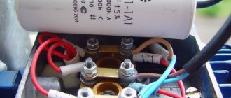
The contacts themselves are supplied in a bag. Since this series is quite simple but at the same time perfectly performs its tasks, and the contactor on my sample is only 24A, we will leave this fact in question. Underneath there is indeed a diode bridge, which is mounted in a hinged manner, and a varistor to limit voltage surges at the contactor input and coil protection. In production, contactors and magnetic starters are usually used to control motors, pumps, as well as in remote control circuits for many other devices and lighting. These are additional contacts that are hung on the contactor in all directions, this is a blocking and a bunch of other things.
It can be used for both direct and alternating current. It is to them that voltage must be applied or removed so that the power contacts open or close. The most obvious example of how such a combination works is the system for turning on and off all the lights in an apartment from one place. And now, understanding the logic of operation and the order of connection, you will be able to independently develop and implement interesting, and most importantly useful equipment control schemes using contactors. These contactors are almost always custom-made, so don’t expect to be lucky and buy them quickly.
Therefore, unlike mechanical ones, they can be used in domestic environments, where most other switching devices are susceptible to strong vibration. Actually, this is what you need to know about the EN series. Well, let me also note that most often contactors have 4 contacts per closure, since most often they actually control three-phase loads. It contains instructions and four metal brackets taped to the bottom. How to connect a contactor
Conventional modular contactor: what is it for?
A modular contactor is an electromagnetic electrical unit that can be controlled at a distance, in remote mode. Such devices are needed for switching or, in other words, connecting and disconnecting current in a circuit.
Such a contactor can use direct or alternating current for its operation, and also have from one to four poles of other contacts. Since this device is an electromagnetic device, the force for the connector and connection of contacts is created directly by the electromagnet.
Most often, a modular contactor is used to control the operation of heating pumps, various ventilation devices, and lighting devices. Helps in automation of building engineering equipment. It is also needed on the electrical panel in the apartment and when creating any automatic circuits.
This device has a number of advantages over other modular devices:
- Absolute noiselessness during operation;
- The presence of a built-in diode bridge capable of rectifying alternating current;
- Simple installation and ease of use;
- Ability to connect to any network;
- Using the device at high power;
- Compact dimensions allow it to be fixed to a DIN rail with a latch;
- It is possible to suppress interference that negatively affects the operation of the device.
Also, depending on the brand and type of device, it can be supplemented with various relays, sensors or other devices used in electrical engineering.
If you need to choose a good contactor or starter, then you should pay attention to companies such as Abb, TDM Electric (KM63 series) and others.
Modular contactors: a good solution
Modular contactors of the electromagnetic type are more popular than mechanical ones. The reason is a number of undeniable advantages:
- work without vibrations and noise;
- possibility of use with direct and alternating current;
- The range includes models for single-phase and three-phase networks;
- small overall dimensions.
Connecting a modular contactor is within the capabilities of a novice electrician. But professionals strongly recommend involving experienced specialists in connecting the device. Especially when it comes to installing a contactor in a large manufacturing plant with a continuous cycle of work.
Electromagnetic contactor and its device
The design of an electromagnetic contactor is an electrical switching device, where the movement and socket of the contacts is carried out by an opening drive, the main element of which is an electromagnetic coil.
To build a control circuit for such a contactor, as well as connect any other elements to it, its design should include a normally closed and normally open additional contact.
Before using an electromagnetic contactor, you should first carefully familiarize yourself with its operating principle and design.
The classification and types of contactors look like this:
- According to the type of current in the main and control circuits;
- By number of poles;
- According to the voltage of the main circuit and the incoming coil;
- By the presence or, conversely, absence of auxiliary contacts.
In addition, the difference between contactors from each other may lie in installation, types of conductor connections, or other actions and features.
Design of electromagnetic contactors:
- The main contacts are “responsible” for connecting and disconnecting the power of the circuit;
- Arc extinguishing system – “extinguishes” electric arcs with a magnetic field when the main contacts are disconnected;
- Electromagnetic system – carries out remote control of the contactor, consists of a coil, core, armature and fasteners;
- Block contacts – control control and signaling circuits.
Contactor circuits, consisting of current-carrying elements, as a rule, have a standard appearance and differ only in the number and type of coils or contacts.
Connection diagram for abb esb 20-20 contactor via switch
A contactor, which is controlled by a switch, is used to turn energy-consuming equipment on and off. The most obvious example of how such a combination works is the system for turning on and off all the lights in an apartment from one place.
Such a main switch is usually installed at the exit from the apartment. When leaving home, you can use it to turn off all the lights at once. The reverse procedure awaits you when you return; by pressing the switch key, you turn on all the lights that were working before leaving.
To implement this logic of lighting operation, you will need a contactor and a switch. ABB ESB 20-20 modular contactor , paired with a conventional single-key light switch.
Before we look at the connection diagram in detail, a few words about this contactor model.
Each symbol in the name of ABB contactors has a specific meaning.
Typically the marking looks like this:
ABB series xx-yz
Amperage voltage , where
ABB is the name of the manufacturer
series – Equipment series XX – current for which the contacts are designed Y – Number of contacts to be closed (normally open/open NO) Z – Number of contacts to be opened (normally closed/closed NC)
amperage – Rated current, voltage – Operating voltage
We talked in detail about how a contactor is designated on single-line diagrams HERE.
The ABB 20-20 modular contactor we selected:
– belongs to the ESB series, considered “household”;
– The rated current for which the contacts are designed is 20A;
– contains 2 independent closed contacts, which, until a signal is received, are normally open;
This logic of contactor operation (normally open contacts) when controlling a switch is most preferable in most cases and allows you to operate a load of up to 40A (2 pairs of contacts of 20A each).
It is more convenient to use a modular contactor with a 220V AC coil (the coil voltage is indicated on the device body, in our case it is 250 Volts “
Modular contactor: connection diagram via button and relay
The operating principle of a modular contactor is to close the working contacts under the influence of a magnetic field. However, this device is not intended to protect the electrical circuit from short circuit or overload. Therefore, when creating a connection diagram, it is necessary to “put” circuit breakers, fuses or a thermal relay there.
The modular contactor is usually mounted on a DIN rail and switches both alternating and direct current.
The contactor connection diagram using a button looks like this:
- By pressing the “Start” button, the electromagnet receives power and turns on;
- The contacts close during this process, which causes voltage to be supplied to the motor;
- Block - the contact also closes;
- When you press “Stop,” the power to the device stops, the power elements disconnect the circuit and the motor turns off.
As for the thermal relay, its purpose is to protect the device from overheating. As the current in the motor stator increases, the relay elements also heat up. As soon as they reach a certain temperature, the circuit will break and the device will turn off.
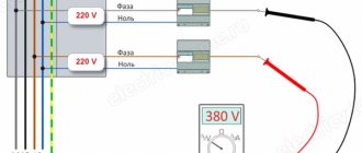
Connection diagram for ABB esb 20-20 contactor for 220V via a switch
Below is a visual diagram of the operation of a contactor through a switch.
It is assembled as follows:
“Phase” is supplied to the switch, which, having passed through it, returns to the control terminal A2 of the contactor. “Zero” is permanently connected to the second terminal A1. A phase is also connected to terminal 1 of the contactor, and a conductor going to the load is connected to terminal 2.
The principle of operation is simple: as soon as you press the switch key, electric current flows to the contactor terminal A1, and therefore to the coil. Next, according to the principle of an electromagnet, the internal contacts, which are normally open, are closed, and the electric current flows to consumers - electrical equipment. As soon as you click the switch key again, the electrical circuit is broken and the contacts inside the modular contactor open, de-energizing the equipment. It's quite simple.
To the second terminals 3-4, you can connect another load up to 20A, for example, a second group of lamps. Accordingly, in total, the contactor will withstand about 9 kW (current - 40A) power.
If you assemble a similar circuit without using a contactor , simply passing the phase of the common power cable of all lighting groups through a switch, problems immediately arise:
– You are limited by the maximum current that the switch can withstand, rarely more than 10A.
– Since the switch does not have any contact protection systems, it would quickly fail, the contact pads would burn out or the housing would melt. A fire may occur.
As you can see, there is nothing complicated about connecting a contactor through a switch. And now, understanding the logic of operation and the order of connection, you will be able to independently develop and implement interesting, and most importantly useful equipment control schemes using contactors.
AC contactor: differences from direct current
Contactors can be either AC or DC. The latter are available with a current range of up to 630A, with one or two poles. Their characteristics differ from those of alternating current devices, which are created mainly with three poles, in the range from 100 to 1000A.
The mode of switching on devices with alternating current differs from the constant mode in that it is more difficult to start due to the starting current of electric motors with a squirrel-cage rotor.
You can familiarize yourself with the differences between an AC contactor and a DC contactor on your own on the Internet or using special literature
- DC devices – control DC electrical circuits and interact with the same electromagnet;
- AC units - their actions extend to AC circuits in contact with an AC or DC electromagnet.
Due to simpler arc extinguishing conditions, the contact opening is more modest compared to DC contactors, which makes it possible to reduce the size of the electromagnet.
Where and why is it used?
Most often, a modular contactor is used to control and switch a heating pump and other various devices (for example, in ventilation systems). They have become popular and in demand when assembling panels in apartments and various automation systems. For example, control of light, well pump, automatic reserve switching circuit, and so on. Why? Because the contactor fits perfectly with other modular devices, without disturbing the ergonomics of the switchboard. You can verify this by looking at the visual example in the photo:
It is worth remembering that the mains voltage should be no more than 380 Volts at a frequency of 50 Hz. But despite this, the contactor can operate at high powers. There are several other advantages of this device. Such as the almost complete absence of noise and vibration, which has a rather positive effect when used not only in a home panel, but also in public places (hospital, apartment, schools, institutes, etc.), since other switching devices are too susceptible to strong vibration.
By the way, size matters. After all, the small size of the modular contactor allows it to be installed on a DIN rail. The design includes arc-extinguishing chambers to extinguish the arc that occurs when the current load changes. In addition, there are single-phase and two-phase contactors, which allows you to connect to any network.
You can learn more about modular contactors by watching this video:
What is it for?
Very often, such an electromagnetic device is used to control and switch heating devices, pumps, and ventilation systems. When contactors first appeared, they were not particularly popular, but then they became famous and indispensable for use in apartment panels and automation systems. There are many examples: the operation of lighting fixtures, pump control, turning on reserves in automatic mode, etc. How did this happen? Everything is very simple, because the contactor fits perfectly and ergonomically into the panel and becomes invisible next to other modules.
It is worth understanding that when using this device, the network should not have more than 380 V voltage at a frequency of 50 Hz, but it can operate at higher powers, withstanding significant voltage drops.
Important! Another advantage of using such a device is the complete absence of noise and vibration on its part. This means that you can install it at home or in public places and not be afraid that it will cause discomfort.
There are such mechanisms of relatively large and small sizes. The latter type can even be connected to a DIN rail. The design of the equipment contains special chambers for extinguishing arcs that appear as a result of changes in current loads.
Note! There are not only single-phase, but also three-phase contactors, which allows you to connect them to almost any electrical circuit.