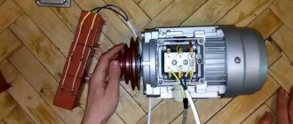
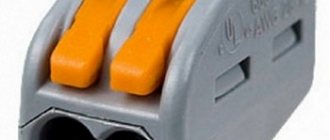
Connection diagram for motor via capacitor
There are 2 types of single-phase asynchronous motors - bifilar (with a starting winding) and capacitor. Their difference is that in bifilar single-phase motors the starting winding operates only until the motor accelerates. Afterwards it is turned off by a special device - a centrifugal switch or a start-up relay (in refrigerators). This is necessary because after overclocking it reduces efficiency.
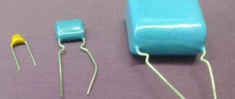
In capacitor single-phase motors, the capacitor winding runs all the time. Two windings - the main and auxiliary, they are shifted relative to each other by 90°. Thanks to this, you can change the direction of rotation. The capacitor on such engines is usually attached to the housing and is easy to identify by this feature.
Connection diagram for a single-phase motor via a capacitor
When connecting a single-phase capacitor motor, there are several options for connection diagrams. Without capacitors, the electric motor hums, but does not start.
- 1 circuit - with a capacitor in the power supply circuit of the starting winding - starts well, but during operation the power it produces is far from rated, but much lower.
- 3, the connection circuit with a capacitor in the connection circuit of the working winding gives the opposite effect: not very good performance at start-up, but good performance. Accordingly, the first circuit is used in devices with heavy starting, and with a working capacitor - if good performance characteristics are needed.
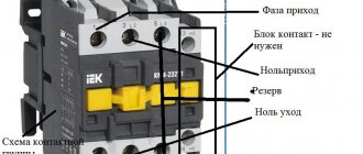
- Diagram 2 - connecting a single-phase motor - install both capacitors. It turns out something between the options described above. This scheme is used most often. She's in the second picture. When organizing this circuit, you also need a PNVS type button, which will connect the capacitor only during the start time, until the motor “accelerates”. Then two windings will remain connected, with the auxiliary winding through a capacitor.
Capacitor in AC circuit
Let's assemble a circuit with a capacitor in which an alternating current generator creates a sinusoidal voltage. Let's look at what happens in the circuit when we close the key. We will consider the initial moment when the generator voltage is zero. In the first quarter of the period, the voltage at the generator terminals will increase, starting from zero, and the capacitor will begin to charge. A current will appear in the circuit, but at the first moment of charging the capacitor, despite the fact that the voltage on its plates has just appeared and is still very small, the current in the circuit (charge current) will be the greatest.
It will be interesting➡ What are flat capacitors
As the charge on the capacitor increases, the current in the circuit decreases and reaches zero at the moment when the capacitor is fully charged. In this case, the voltage on the capacitor plates, strictly following the generator voltage, becomes at this moment maximum, but of the opposite sign, i.e., directed towards the generator voltage. Thus, the current rushes with the greatest force into the charge-free capacitor, but immediately begins to decrease as the capacitor plates are filled with charges and drops to zero, fully charging it.
Material on the topic: description and scope of application of the trimming resistor.
Let us compare this phenomenon with what happens to the flow of water in a pipe connecting two communicating vessels, one of which is filled and the other empty. One has only to pull out the valve blocking the path of water, and water will immediately rush from the left vessel under high pressure through the pipe into the empty right vessel. However, immediately the water pressure in the pipe will begin to gradually weaken, due to the leveling of the levels in the vessels, and will drop to zero. The water flow will stop. Similarly, the current first flows into an uncharged capacitor, and then gradually weakens as it charges.
With the beginning of the second quarter of the period, when the voltage of the generator begins slowly at first, and then decreases faster and faster, the charged capacitor will be discharged to the generator, which will cause a discharge current in the circuit. As the generator voltage decreases, the capacitor is discharged more and more and the discharge current in the circuit increases. The direction of the discharge current in this quarter of the period is opposite to the direction of the charge current in the first quarter of the period. Accordingly, the current curve, having passed the zero value, is now located below the time axis.
By the end of the first half-cycle, the voltage on the generator, as well as on the capacitor, quickly approaches zero, and the current in the circuit slowly reaches its maximum value. Remembering that the magnitude of the current in the circuit is greater, the greater the amount of charge transferred along the circuit, it will become clear why the current reaches its maximum when the voltage on the capacitor plates, and therefore the charge of the capacitor, quickly decreases.
With the beginning of the third quarter of the period, the capacitor begins to charge again, but the polarity of its plates, as well as the polarity of the generator, changes to the opposite, and the current, continuing to flow in the same direction, begins to decrease as the capacitor is charged. At the end of the third quarter of the period, when the voltages across the generator and capacitor reach their maximum, the current becomes zero.
In the last quarter of the period, the voltage, decreasing, drops to zero, and the current, changing its direction in the circuit, reaches its maximum value. This ends the period, after which the next one begins, exactly repeating the previous one, etc.
So, under the action of the alternating voltage of the generator, the capacitor is charged twice per period (the first and third quarters of the period) and discharged twice (the second and fourth quarters of the period). But since the alternating charges and discharges of the capacitor are accompanied each time by the passage of charging and discharging currents through the circuit, we can conclude that an alternating current passes through the circuit with the capacitance.
It will be interesting➡ A few facts about electrolytic capacitors
Connection diagram for a three-phase motor via a capacitor
Here, the voltage of 220 volts is distributed into 2 series-connected windings, where each is designed for this voltage. Therefore, the power is lost almost twice, but such an engine can be used in many low-power devices.
The maximum power of a 380 V motor in a 220 V network can be achieved using a delta connection. In addition to minimal power losses, the engine speed also remains unchanged. Here, each winding is used for its own operating voltage, hence the power.
It is important to remember: three-phase electric motors have higher efficiency than single-phase 220 V motors . Therefore, if there is a 380 V input, be sure to connect to it - this will ensure more stable and economical operation of the devices. To start the motor, you will not need various starters and windings, because a rotating magnetic field appears in the stator immediately after connecting to a 380 V network.
Engine operating principle
When an electric motor is operating, connected to a three-phase 380 V network, voltage is sequentially applied to each of its windings and a current flows through each of them, creating an alternating magnetic field that affects the rotor, movably mounted on bearings, which causes it to rotate. To start with this type of operation, no additional elements are needed.
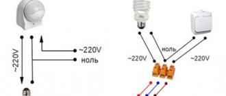
If one of the three-phase asynchronous electric motors is connected to a single-phase 220 V network, then no torque will arise and the motor will not start. To run three-phase devices from a single-phase network, many different options have been invented. One of the simplest and most common among them is the use of phase shift. For this purpose, various phase-shifting capacitors are used for electric motors, through which the third phase contact is connected.
In addition, there must be one more element. This is the starting capacitor. It is designed to start the engine itself and should only work at the moment of starting for about 2-3 seconds. If it is left on for a long time, the motor windings will quickly overheat and it will fail. To implement this, you can use a special switch that has two pairs of switchable contacts. When the button is pressed, one pair is fixed until the next press of the Stop button, and the second will be closed only when the Start button is pressed. This prevents motor failure.
Online calculation of motor capacitor capacity
Enter data for calculating capacitors - motor power and efficiency
There is a special formula that can be used to calculate the required capacity accurately, but you can easily get by with an online calculator or recommendations that are derived from many experiments:
The working capacitor is taken at the rate of 0.8 μF per 1 kW of engine power; The launcher is selected 2-3 times more.
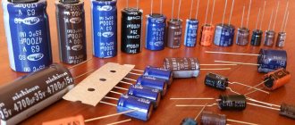
Capacitors must be non-polar, that is, not electrolytic. The operating voltage of these capacitors must be at least 1.5 times higher than the network voltage, that is, for a 220 V network we take capacitors with an operating voltage of 350 V and higher. To make starting easier, look for a special capacitor in the starting circuit. They have the words Start or Starting in their markings.
Starting capacitors for motors
These capacitors can be selected using the method from smallest to largest. Having thus selected the average capacity, you can gradually add and monitor the operating mode of the engine so that it does not overheat and has enough power on the shaft. Also, the starting capacitor is selected by adding until it starts smoothly without delays.
During normal operation of three-phase asynchronous electric motors with capacitor start, connected to a single-phase network, it is assumed that the capacitance of the capacitor will change (decrease) with increasing shaft speed. At the moment of starting asynchronous motors (especially with a load on the shaft) in a 220 V network, an increased capacity of the phase-shifting capacitor is required.
Automatic connection of a three-phase motor to a 220 V network.
In order not to connect the starting capacitor every time to start the electric motor, you can assemble a simple time relay circuit that will do this automatically. This is relevant for systems where you often have to start motors using a starting capacitor.
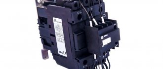
You will need two devices: a time relay and a starter.
They ask a lot, but can it be done without a starter?
For the most part, the contacts of time relays and similar devices are not designed to switch a heavy load like an electric motor. Imagine a cargo crane or an elevator powered and connected/disconnected from a home outlet - the same thing applies here.
And starters or contactors are specially designed to work with electric motors, one might say “do not spill water.”
But not all
. There are different categories of these devices; for motors the AC-3 category is often used. Also, when inductive loads are turned off, overvoltage and sparking occur. The contacts of the time relay are also not designed for this, but those of the starter are suitable.
The starters/contactors themselves are selected according to the power of the electric motor and application categories (AC-3, etc.).
The power supply for starter coils and time relays comes in different voltages. For a single-phase 220 V network, they should accordingly be 220 V.
How to connect.
The circuit is made on the H3Y-2 timer; 0-30 sec. from China. This is probably the most affordable time relay (more on it at the end of the article). I usually assemble the control circuit first:
Numbers and letters are designated for a reason. For most electrical products they are the same and help to assemble circuits.
Next, I add starting and running capacitors with the motor terminal block:
The logic of the circuit is as follows: when power is supplied, the time relay immediately turns on the contactor, and it, in turn, connects the starting capacitor to the working capacitor. This results in a parallel connection of the containers. And as the relay counts down the set time delay, it turns off the starting capacitor.
It should not turn out that the working one is powered from the phase, and the starting one from zero, or they go to different terminals of the motor. I don't even know what will happen. Strict parallel connection only
.
Selection of capacitors.
As a quick aside, the worker takes 7 microfarads for every 100 watts of engine power and 1x-3x the worker’s starting capacity, depending on the starting conditions.
The capacitors themselves are non-polar and differ from each other. The worker is designed for long work
, is connected to the engine at all times. Its rated voltage is about 450 V. The starter operates for several seconds, its rated voltage is 300-350 V.
A simple calculation is suitable for a sufficiently loaded motor, but if it is underloaded, problems may arise, details here. However, if it is loaded, then they can too.
Selecting a starting capacitor for an electric motor
A modern approach to this issue involves the use of special calculators on the Internet that perform quick and accurate calculations.
To carry out the calculation, you should know and enter the following indicators:
- Motor winding connection type : delta or star. The capacitance also depends on the type of connection.
- Engine power is one of the determining factors. This indicator is measured in Watts.
- Mains voltage is taken into account in calculations. As a rule, it can be 220 or 380 Volts.
- Power factor is a constant value that is often 0.9. However, it is possible to change this indicator during calculation.
- The efficiency of the electric motor also affects the calculations performed. This information, as well as others, can be found by studying the information printed by the manufacturer. If it is not there, you should enter the engine model on the Internet to search for information about what the efficiency is. You can also enter an approximate value, which is typical for such models. It is worth remembering that efficiency may vary depending on the condition of the electric motor.
Such information is entered into the appropriate fields and an automatic calculation is carried out. At the same time, we obtain the capacity of the working condensate, and the starting condensate should have an indicator 2.5 times greater.
You can carry out such a calculation yourself.
To do this, you can use the following formulas:
- For the star winding connection type, the capacitance is determined using the following formula: Cр=2800*I/U. In the case of a triangle connection of the windings, the formula Cр=4800*I/U is used. As you can see from the information above, the type of connection is the determining factor.
- The above formulas determine the need to calculate the amount of current that passes through the system. For this, the formula is used: I=P/1.73Uηcosφ. For the calculation you will need engine performance indicators.
- After calculating the current, you can find the capacitance indicator of the working capacitor.
- The starting one , as previously noted, should be 2 or 3 times higher in capacity than the working one.
When choosing, you should also consider the following nuances:
- range .
- Possible deviation from the calculated capacity.
- Insulation resistance.
- Loss tangent.
Usually, the above parameters are not paid much attention. However, they can be taken into account to create an ideal electric motor power system.
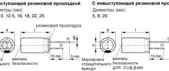
Overall dimensions can also be a determining factor. In this case, the following dependence can be distinguished:
- Increasing the capacitance leads to an increase in the diametrical size and outlet distance.
- The most common maximum diameter is 50 millimeters with a capacitance of 400 µF. At the same time, the height is 100 millimeters.
In addition, it is worth considering that on the market you can find models from foreign and domestic manufacturers. As a rule, foreign ones are more expensive, but also more reliable. Russian versions are also often used when creating an electric motor connection network.
Disadvantages of the scheme.
1. After turning off, a charge remains on the starting capacitor and will remain there for quite a long time, if not indefinitely. Therefore, a system for its discharge must be provided. I think a 380 volt light bulb or a 500 kOhm resistor connected in parallel to it will do.
2. There is no feedback from the engine. If the set time is not enough to start (let’s say it was enough in the summer, but not enough in the winter), then the motor may not start, it will simply remain humming and after some time it will burn out.
Other disadvantages are possible.
How to connect a capacitor to an electric motor: step-by-step instructions!
In the previous article we answered the question: is it possible to connect a three-phase motor to a single-phase network? Today we will talk about how to connect a three-phase motor to a single-phase network using a capacitor.
IMPORTANT!
Electrical installation work should only be carried out in full compliance with
safety requirements
.
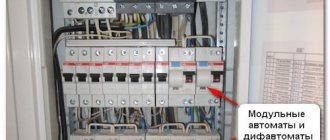
a two-pole circuit breaker on a DIN rail
6 Ampere with time-current characteristic C;
the starting
and
running capacitors
to the wall of the control box using clamps ;
• install a grounding bus
.
a three-core cable of type KG from the bottom of the control box
for voltage 380V with a cross-section of at least 1.5 mm².
We install a plug
on the other end of the cable .
We terminate the blue and brown wires with lugs and clamp them in the lower terminals of the circuit breaker, and we terminate the yellow-green wire and connect it to the grounding bus.
The PNVS starter, installed on top of the control box, has three contacts on both sides. When you press the Start button, all six contacts close, while the outer four contacts are fixed. After the engine reaches rated speed and enters operating mode, the “Start” button must be released so that the central contacts connecting the starting capacitor open. To complete the work, press the “Stop” button, after which the outer contacts open.
Model overview
capacitor CBB-60
There are several popular models that can be found on sale.
It is worth noting that these models differ not in capacity, but in type of design:
- Metallized polypropylene versions
of the SVV-60 brand. The cost of this version is about 300 rubles. - NTS film brands
are somewhat cheaper. With the same capacity, the cost is about 200 rubles. - E92
– products of domestic manufacturers. Their cost is small - about 120-150 rubles for the same capacity.
There are other models, often differing in the type of dielectric used and the type of insulating material.
- Often
, the operation of an electric motor can occur without including a starting capacitor in the circuit. - to include this element in the circuit
only if the load is started. - Also
, high engine power also requires the presence of similar elements in the circuit. - Particular attention
should be paid to the connection procedure, since violation of the integrity of the structure will lead to its malfunction.
To connect a three-phase motor to a single-phase network, capacitors are used to start electric motors. They can be of different modifications, so the question of how to correctly calculate them and what to pay attention to when choosing is not at all idle. Before answering the question of what kind of capacitor is needed, it is worth remembering what it even is?
- Design and principle of operation
- Practical use
- Three-phase network Three-phase motors
- Single-phase motors
Connection Schemes for Single-Phase Electric Motors Through a Capacitor
Thanks to inductance, electromotive force and a shift of magnetic fluxes in phase and time appear. Electric motor windings Laying windings in the stator of a single-phase electric motor The design of any single-phase electric motor involves the use of at least three coils.
There are models in which the starting winding works not only during startup, but throughout the rest of the time. And a pair of wires comes out from the stator and the rotor armature.
This is precisely the reason for the popularity of the engine among the population. How to simply connect a three-phase motor with a triangle and a star to a 220 network, through a capacitor.
Torque is created through the use of additional starting windings. So, step by step, we figured out how to connect a three-phase asynchronous electric motor to a single-phase network and what you need to calculate and know for this.
In this case, the engine hums, the rotor remains in place. The size of the capacitor is usually indicated on the motor nameplate and depends on its design.
It says that the motor can only be connected via a star. Ryzhenkov Share this article with your friends: Join our groups on social networks:.
The starting and operating windings of single-phase motors differ in both the cross-section of the wire and the number of turns. This will be one of the network wires.
What else do you need to connect? The collector single-phase model has in its design an excitation winding and two brushes. Selection of a working capacitor for an electric motor.
Simple ways to connect an electric motor
The easiest way to connect a three-phase electric motor to a household electrical network is to use a frequency converter. Power losses will be minimal, but such a device often costs more than the engine itself.
A frequency converter will only become cost-effective if there is a large volume of equipment used.
Another method uses the winding of the asynchronous electric motor itself to convert the supply voltage. The scheme will turn out to be bulky and massive . The capacitor for starting the electric motor is connected according to one of two popular schemes
- triangle;
- star.
Connecting the motor according to the star and delta circuits
When implementing connections using these methods, it is important to minimize power losses.
Calculation of motor capacitor capacity
The winding with a smaller cross-section is the starting one. Such devices have a power factor greater than that of the short-circuited devices described above and develop greater torque in comparison with them. You can do this yourself or use online calculators. The circuit with a working capacitor does not provide for disconnecting the additional winding after starting and accelerating the engine.
From a single-phase network, three-phase devices operate using capacitive or inductive-capacitive phase-shifting circuits.
Capacitors Our readers recommend! How to connect the electric motor of a washing machine Modern washing machines can have either commutator or three-phase motors.
Each of the listed connection diagrams is suitable for use in the operation of asynchronous single-phase electric motors.
Design and principle of operation
The capacitor uses the property of conductors to charge when they are close to each other. This is called polarization. But so that this charge can be removed, two plates are used, one opposite the other, with a dielectric between them. If they are separated, the charge cannot be removed.
Modern technologies make it possible to produce capacitive devices of various models and purposes. These include devices that operate only in DC circuits, and for starting electric motors, and equalizing models. All that remains for the end user is to choose the appropriate one, calculate the parameters and put it in the electrical circuit.
Connecting a single-phase electric motor: using a magnetic starter
But there is another way - connecting a single-phase electric motor as a generator to produce three-phase voltage.
Buttons with a group of contacts or relays are used as a short-term switch. According to the diagram shown in Figure 2, the connections were made without a neutral.
The function of the centrifugal switch is to cut off the starting phase when the rotor reaches its rated speed. Remember that when connecting a commutator electric motor without an electronics unit, it will only operate at maximum speed, and when starting there will be a strong jerk, high starting current, and sparking on the commutator.
In capacitor single-phase motors, the capacitor winding runs all the time. Therefore, once it is connected to the network, all capacitors involved in the circuit must be at least V. The magnetic field of the main winding maintains rotation for a long time.
For example, for making emery or a homemade drilling machine. It is necessary to use only the capacitors that are included in the delivery kit. How to calculate capacitance The capacitance of a capacitor, which is installed in the connection circuit of a three-phase electric motor connected to a network with a voltage of V, depends on the circuit itself. It is important to remember: three-phase electric motors have higher efficiency than single-phase V motors.
The magnetic field of the main winding maintains rotation for a long time. The solution is to install a 3-pole switch. This procedure is implemented by simply changing the order in which the starting winding is turned on when it is connected to the working winding. This is due to the fact that when only the working winding C1-C2 is connected to the network, a single-phase capacitor motor will have a pulsating magnetic field rather than a rotating one, that is, it will not start. It is necessary to connect chokes to each of the network wires to eliminate interference.
The magnetic circuit of single-phase motors contains a two-phase winding, consisting of a main winding and a starting winding. Control of starting current indicators in such motors is carried out by a frequency converter. This will be one of the network wires. The most convenient is a magnetic starter controlled from alternating current. All containers included in the circuit must be of the same type.
If after this the engine turns out to be hot, then: The bearings may be dirty, jammed, or simply worn out. The idea of using a starting capacitor is to include it in the circuit only at the moment the motor starts. Machines for processing raw materials, etc. Connecting a capacitor. How to connect a capacitor to an electric motor. Scheme.
Purpose and benefits
Capacitors of the type in question are used in the connection system of an asynchronous motor.
In this case, it works only at the time of start-up, until the operating speed is reached. The presence of such an element in the system determines the following:
- The starting capacitance makes it possible to bring the state of the electric field closer to circular.
- is being carried out .
- increases and engine performance improves significantly.
Without the presence of this element in the system, the service life of the engine is significantly reduced. This is due to the fact that a complex start-up leads to certain difficulties.
The AC mains can serve as a power source when using this type of capacitor. Almost all used versions are non-polar; they have a comparatively higher operating voltage for oxide capacitors.
The advantages of a network that has a similar element are as follows:
- Easier engine starting.
- service life is significantly longer.
The starting capacitor operates for several seconds when the engine starts.
Connecting a single-phase motor via a capacitor - 3 circuits
What happens with this?
If the heating is quite noticeable, then you need to look for its causes. If the capacity is significantly exceeded, intense heating will begin.
It is necessary that the rated voltage of the capacitor is equal to or greater than the calculated one. This is the optimal solution for achieving average performance. Afterwards it is turned off by a special device - a centrifugal switch or a start-up relay in refrigerators.
Secondly, and most importantly, the author was convinced in practice that even an extremely accurate calculation is not a guarantee of the correct operation of the engine. One of the windings is connected directly to the network, and the second is connected using a capacitor. In the geometric dimension, the windings in the stator are placed opposite each other. So, step by step, we figured out how to connect a three-phase asynchronous electric motor to a single-phase network and what you need to calculate and know for this.
Asynchronous or collector: how to distinguish
Two of them are stator structural elements connected in parallel. Based on the maximum current flowing through it, a magnetic starter belongs to one of seven standardized groups. In fact, the launcher only works for seconds. As a rule, the resistance of the windings will be no more than several tens of ohms.
For example, on the operating conditions of the engine itself, on the connection diagram, on the capacitors, or, more precisely, on their capacity. For this purpose, the circuit provides for the presence of a special button designed to open the contacts after the rotor reaches a given speed level. Another example when measurements can show 10 ohms, 10 ohms, 20 ohms.
When you need to quickly spin up the engine, a circuit with a starting capacitor is used. It makes no difference what kind of working winding you have and what kind of starting winding. For single-phase asynchronous AC motors with a running capacitor, the auxiliary winding is permanently connected through a capacitor. But in any case, losses will range from 30 to 50 percent.
The most common motors of this type can be divided into two groups: single-phase motors with a starting winding and motors with a running capacitor. She's in the second picture. Connect a three-phase motor to a single-phase network. Starting and running capacitors.
Source