What is a capacitor?
A device that stores electricity in the form of electrical charges is called a capacitor.
The amount of electricity or electric charge in physics is measured in coulombs (C). Electrical capacitance is calculated in farads (F).
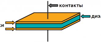
A solitary conductor with an electrical capacity of 1 farad is a metal ball with a radius equal to 13 radii of the Sun. Therefore, a capacitor includes at least 2 conductors, which are separated by a dielectric. In simple device designs, paper is used.
The operation of a capacitor in a DC circuit is carried out when the power is turned on and off. Only during transient moments does the potential on the plates change.
The capacitor in the AC circuit recharges at a frequency equal to the frequency of the power source voltage. As a result of continuous charges and discharges, current flows through the element. A higher frequency means the device recharges faster.
The resistance of the circuit with a capacitor depends on the frequency of the current. At zero frequency of direct current, the resistance value tends to infinity. As the AC frequency increases, the resistance decreases.
Capacitor formulas
For any capacitor the formula is valid:
where C is the capacitance of the capacitor; q is the charge value of one of the capacitor plates; – potential difference between its plates.
The capacitance of a capacitor between the plates of which there is a dielectric (C) (the dielectric constant of which is equal to times greater than the capacitance of the same air capacitor ():
To calculate the capacitance of a flat capacitor, use the formula:
where is the electrical constant; S – area of each (or smallest) plate; d – distance between plates.
The capacitance of a flat capacitor containing N layers of dielectric (the thickness of the i-th layer is equal to , the dielectric constant of the i-th layer is defined as:
The electrical capacitance of a cylindrical capacitor is calculated as:
where l is the height of the cylinders; – radius of the outer lining; – radius of the inner lining.
The capacitance of a spherical (ball) capacitor is found by the formula:
where are the radii of the capacitor plates.
Where are capacitors used?
The operation of electronic, radio engineering and electrical devices is impossible without capacitors.
In electrical engineering, the device is used to shift phases when starting asynchronous motors. Without a phase shift, a three-phase asynchronous motor in a single-phase alternating network does not function.
Capacitors with a capacity of several farads - ionistors - are used in electric vehicles as engine power sources.
To understand why a capacitor is needed, you need to know that 10-12% of measuring devices operate on the principle of changing electrical capacitance when environmental parameters change. The capacitance reaction of special devices is used for:
- recording weak movements through increasing or decreasing the distance between the plates;
- determining humidity by recording changes in dielectric resistance;
- measuring the level of liquid, which changes the capacity of the element when filled.
It is difficult to imagine how automation and relay protection are designed without capacitors. Some protection logics take into account the recharge rate of the device.
Capacitive elements are used in circuits of mobile communication devices, radio and television equipment. Capacitors are used in:
- high and low frequency amplifiers;
- power supplies;
- frequency filters;
- sound amplifiers;
- processors and other microcircuits.
It is easy to find the answer to the question of what a capacitor is needed for if you look at the electrical diagrams of electronic devices.
What types of capacitors are there?
There are different classifications of capacitors used in electronic circuits. Most often, such devices are divided into types according to the type of dielectric used in them. Based on the characteristics of the dielectric, the following types can be distinguished:
- with liquid dielectrics.
- vacuum, in which there is no dielectric.
- with a solid organic dielectric.
- with gas dielectric.
- electrolytic or oxide semiconductor with an electrolyte or oxide metal layer.
- with a solid inorganic dielectric.
The second classification option is based on the probability of fluctuations in the capacity value. Based on this characteristic, the following devices can be distinguished:
- Variables – which can change capacitance due to voltage or temperature conditions.
- Constant - the size of the capacity does not change throughout its service life.
- Trimmers - with variable capacity, used for periodic or one-time adjustment of circuits.
According to the scope of operation, all capacitors are divided into the following types:
- Low voltage, used in low voltage networks.
- High voltage, used in high voltage networks.
- Impulse – capable of releasing a short-term impulse.
- Starters - for starting the electric motor.
- Noise suppressing.
There are other classes based on areas of application, but in practice they are extremely rare.
The table below shows the most common capacitors and their designations in the diagrams.
A capacitor is an electrical (electronic) component consisting of two conductors (plates) separated by a layer of dielectric. There are many types of capacitors. They are mainly divided according to the material from which the plates are made and the type of dielectric used between them.
Characteristics and properties
Capacitor parameters that are used to create and repair electronic devices include:
- Capacity - C. Determines the amount of charge that the device holds. The value of the nominal capacity is indicated on the case. To create the required values, the elements are included in the circuit in parallel or in series. Operational values do not coincide with calculated values.
- Resonant frequency - fр. If the current frequency is greater than the resonant one, then the inductive properties of the element appear. This makes work difficult. To ensure the design power in the circuit, it is reasonable to use a capacitor at frequencies below resonant values.
- Rated voltage - Un. To prevent breakdown of the element, the operating voltage is set less than the rated voltage. The parameter is indicated on the capacitor body.
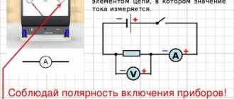
- Polarity. If the connection is incorrect, breakdown and failure will occur.
- Electrical insulation resistance - Rd. Determines the leakage current of the device. In devices, parts are located close to each other. At high leakage current, parasitic connections in the circuits are possible. This leads to malfunctions. Leakage current worsens the capacitive properties of the element.
- Temperature coefficient - TKE. The value determines how the capacitance of the device changes with fluctuations in ambient temperature. The parameter is used when developing devices for operation in harsh climatic conditions.
- Parasitic piezoelectric effect. Some types of capacitors create noise in devices when deformed.
Main settings
The main parameters of capacitors that are used in the design and repair of radio electronics devices are capacitance and rated voltage. In addition, there are several additional parameters that can affect the elements of the circuit. Capacitors have the following main characteristics.
Capacity
This is the most basic parameter that characterizes the accumulation of electrical charge. The value is calculated using various formulas, depending on the design features: flat, cylindrical or round capacitor. In practice, most of them are produced as flat varieties. The capacity of modern devices varies from units of picofarads to tens of thousands of microfarads and even units of farads.
Specific capacity
This relative parameter relates the dimensions to the size of the container. Thus, the higher the specific capacitance, the smaller the dimensions of the structure, however, the electrical strength (operating voltage) may decrease.
Energy Density
This parameter is important when using capacitors as energy storage devices; it determines the amount of energy per unit mass or volume of the element.
Rated voltage
The voltage value at which operating parameters are maintained during the service life is called nominal. The operating voltage must be less than the rated voltage.
Important! Exceeding the rated voltage may result in failure of the element. The electrolytic capacitor may explode in this case.
Contrary to popular belief, an element connected to a circuit with a voltage several times less than the nominal voltage retains all other parameters.
Polarity
These types of capacitors, such as electrolytic ones, often require inclusion in a circuit with respect to polarity. Since such elements are used mainly as storage devices or filters, this is not a problem. Failure to comply with polarity leads to:
- capacity mismatch;
- damage.
The marking must contain information about the polarity of the connection.
Risk of destruction (explosion)
Explosive destruction is typical for electrolytic capacitors. The cause of the explosion is heating, which occurs due to:
- non-compliance with polarity;
- location near heat sources;
- aging (increased leakage and increased equivalent resistance).
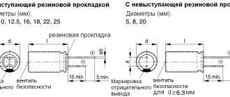
To reduce the consequences of destruction, a safety valve is installed at the end of the body or notches are formed on the lid. This design ensures that with a sharp increase in pressure inside the housing, accumulated gases and electrolyte are released through a valve or a cap broken along the notches. This prevents an explosion, in which the plates and electrolyte are scattered over a large area and cause short-circuiting of the board elements. Cooling the device reduces the likelihood of destruction.
Types of capacitors
Capacitive elements are classified according to the type of dielectric used in the design.
Paper and metal-paper capacitors
The elements are used in circuits with constant or slightly pulsating voltage. The simplicity of the design results in a 10-25% decrease in the stability of characteristics and an increased amount of losses.
In paper capacitors, the aluminum foil plates are separated by paper. The assemblies are twisted and placed in a housing in the shape of a cylinder or rectangular parallelepiped.
The devices operate at temperatures -60...+125°C, with a rated voltage of up to 1600 V for low-voltage devices, above 1600 V for high-voltage devices and a capacity of up to tens of microfarads.
In metal-paper devices, instead of foil, a thin layer of metal is applied to dielectric paper. This helps to produce smaller elements. With minor breakdowns, self-healing of the dielectric is possible. Metal-paper elements are inferior to paper ones in terms of insulation resistance.
Electrolytic capacitors
The design of the products resembles paper ones. But in the manufacture of electrolytic cells, paper is impregnated with metal oxides.
In paperless electrolyte products, the oxide is applied to a metal electrode. Metal oxides have one-way conductivity, which makes the device polar.
In some models of electrolytic cells, the plates are made with grooves that increase the surface area of the electrode. Gaps in the space between the plates are eliminated by pouring electrolyte. This improves the capacitive properties of the product.
The large capacity of electrolytic devices—hundreds of microfarads—is used in filters to smooth out voltage ripples.
Aluminum electrolytic
In devices of this type, the anode plate is made of aluminum foil. The surface is coated with a metal oxide - a dielectric. The cathode plate is a solid or liquid electrolyte that is selected so that the oxide layer on the foil is restored during operation. Self-healing dielectric extends the operating time of the element.
Capacitors of this design require polarity. If you turn it back on, it will break the case.
Devices containing back-to-back polar assemblies are used in 2 directions. The capacity of aluminum electrolytic cells reaches several thousand microfarads.
Tantalum electrolytic
The anode electrode of such devices is made from a porous structure obtained by heating tantalum powder to +2000°C. The material looks like a sponge. Porosity increases surface area.
Using electrochemical oxidation, a layer of tantalum pentoxide up to 100 nanometers thick is applied to the anode. The solid dielectric is made from manganese dioxide. The finished structure is pressed into a compound - a special resin.
Tantalum products are used at current frequencies above 100 kHz. The capacitance is created up to hundreds of microfarads, with an operating voltage of up to 75 V.
Main characteristics
The main operating parameter is capacity, which determines the ability of a particular model to accumulate charge. The nominal and actual capacity should be separated, since in practice the second value may be less. The range of volume values can vary from 1 to 50 μF, and in some cases the maximum reaches 10,000 μF. The energy density indicator is also important, largely determined by the design of the product. Large-format types of capacitors are characterized by the highest density, in which the mass of the plating with electrolyte significantly exceeds the weight of the body. For example, with a capacitance of 10,000 uF with a voltage of 0.45 kW and a mass of about 2 kg, the density can reach 600-800 J/kg. It is precisely such models that are advantageous to use for long-term energy storage. In addition, the operating properties of capacitors are determined by tolerance. We are talking about the error in the ratio of real and nominal capacity indicators. This value is expressed as a percentage and averages 20-30%. In some areas of radio engineering, products with 1% tolerance are used.
What is the difference between polar and non-polar?
Non-polar ones allow the inclusion of capacitors in a circuit without taking into account the direction of the current. The elements are used in filters for variable power supplies and high-frequency amplifiers.
Polar products are connected in accordance with the markings. If turned on in the reverse direction, the device will be damaged or will not work normally.
Polar and non-polar capacitors of large and small capacity differ in dielectric design. In electrolytic capacitors, if the oxide is applied to 1 electrode or 1 side of the paper, film, then the element will be polar.
Models of non-polar electrolytic capacitors, in the designs of which the metal oxide is deposited symmetrically on both surfaces of the dielectric, are included in circuits with alternating current.
Polar ones have a positive or negative electrode marking on the body.
Capacitor positive symbol
On domestic Soviet products, only the positive contact was indicated with a “+” sign. This sign was applied to the case next to the positive terminal. Sometimes in the literature the positive terminal of electrolytic capacitors is called the anode, since they not only passively accumulate charge, but are also used to filter alternating current, i.e. have the properties of an active semiconductor device. In some cases, the “+” sign is also placed on the printed circuit board, close to the positive terminal of the drive located on it.
We advise you to study Thermocouple: what is it?
On products of the K50-16 series, polarity markings are applied to the bottom, made of plastic. For other models of the K50 series, for example K50-6, the “plus” sign is painted on the bottom of the aluminum case, next to the positive terminal. Sometimes imported products produced in the countries of the former socialist camp are also marked on the bottom. Modern domestic products meet global standards.
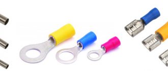
The marking of SMD (Surface Mounted Device) capacitors intended for surface mounting (SMT - Surface Mount Technology) differs from ordinary ones. Flat models have a black or brown body in the form of a small rectangular plate, part of which at the positive terminal is painted over with a silver stripe with a plus sign on it.