Classic starters and contactors are gradually becoming a thing of the past. Their place in automotive electronics, household appliances and industrial automation is occupied by solid-state relays - a semiconductor device in which there are no moving parts.
The devices have different designs and connection diagrams, which determine their scope of application. Before using the device, you need to understand its principle of operation, learn about the features of operation and connection of different types of relays. The answers to the above questions are described in detail in the presented article.
Solid state relay device
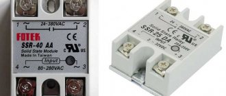
Modern solid-state relays (SSRs) are modular semiconductor devices that act as power electrical switches.
The key operating units of these devices are represented by triacs, thyristors or transistors. SSRs have no moving parts, which makes them different from electromechanical relays.
The size of an SSR largely depends on the maximum load capacity and the ability to dissipate heat by heat transfer and convection (+)
The internals of these devices can vary greatly depending on the type of load being regulated and the electrical circuit.
The simplest solid-state relays include the following components:
- input unit with fuses;
- trigger circuit;
- optical (galvanic) isolation;
- switching unit;
- protective circuits;
- load exit node.
The SSR input node is a primary circuit with a resistor connected in series. A fuse is built into this circuit as an option. The task of the input node is to receive a control signal and transmit a command to the switches switching the load.
With alternating current, galvanic isolation is used to separate the control and main circuits. The principle of operation of the relay largely depends on its design. The trigger circuit responsible for processing the input signal can be included in the optical isolation unit or located separately.
The protective unit prevents overloads and errors from occurring, because if the device breaks down, the connected equipment may also fail.
The main purpose of solid-state relays is to close/open an electrical network using a weak control signal. Unlike electromechanical analogues, they have a more compact shape and do not produce characteristic clicks during operation.
Operating principle of a solid state relay
The work of a solid-state relay is to switch an electrical circuit. Such relays have terminals for control and terminals for switching the controlled circuit. When the required voltage or other signal required by the relay being used is applied, the output circuit will close.
Unlike an electromechanical relay, where all switching operations occur using an electromagnet and mechanical contacts, in a solid-state relay these functions are performed by semiconductor elements. For alternating current relays, these devices are thyristors or triacs, and for direct current, a transistor.
The relay is controlled using a special element - an optocoupler. Due to its use, galvanic isolation appears. The control voltage powers the LED, which begins to glow. Its glow activates a photodiode, the current of which turns on a semiconductor element (thyristor, transistor, etc.), which switches the load.
Based on the type of switching, the following types of relays can be distinguished:
- With zero crossing commutation - when voltage is applied to the input, switching occurs when the sine wave value reaches zero:
- Instantaneous switching - when control voltage appears, switching occurs instantly:
- Phase control - by changing the resistance, the power on the load changes:
Operating principle of TTP
The operation of a solid state relay is quite simple. Most SSRs are designed to control automation in 20-480 V networks.
Optical isolation allows you to create control signals of minimal power, which is critical for sensors operating from autonomous power sources (+)
In the classic version, the device body includes two contacts of the switched circuit and two control wires. Their number may change as the number of connected phases increases. Depending on the presence of voltage in the control circuit, the main load is switched on or off by semiconductor elements.
A feature of solid-state relays is the presence of non-infinite resistance. If the contacts in electromechanical devices are completely disconnected, then in solid-state devices the absence of current in the circuit is ensured by the properties of semiconductor materials.
Therefore, at elevated voltages, small leakage currents may appear, which can negatively affect the operation of connected equipment.
Principle of operation
Solid State Relay Device
A solid state relay is a modular semiconductor device used to make and break electrical circuits. It is presented in the form of transistors, triacs, thyristors. Solid state relays are also called SSR (solid state relay).
The main components that make up the relay are:
- input node;
- circuit breakers;
- trigger circuit;
- interchange;
- switching unit;
- safety circuit;
- output node.
Most solid-state relays are used for automation connected to a 20-480 Volt power supply.
The operating principle of the device is simple. The relay body includes two contacts and two control wires. Their number may vary depending on the phases that were connected. Under the influence of voltage, the main load switches.
When working with relays, you need to take into account that at high voltages there is a risk of small leakage currents that can harm equipment. This is due to the fact that a small resistance remains in the relay.
Classification of solid state relays
The areas of application of relays are varied, therefore their design features can vary greatly, depending on the needs of a particular automatic circuit. SSRs are classified according to the number of connected phases, type of operating current, design features and type of control circuit.
By number of connected phases
Solid-state relays are used both in household appliances and in industrial automation with an operating voltage of 380 V.
Therefore, these semiconductor devices, depending on the number of phases, are divided into:
- single-phase;
- three-phase.
Single-phase SSRs allow you to work with currents of 10-100 or 100-500 A. They are controlled using an analog signal.
It is recommended to connect wires of different colors to the three-phase relay so that they can be connected correctly when installing the equipment
Three-phase solid-state relays are capable of passing current in the range of 10-120 A. Their design assumes a reversible operating principle, which ensures the reliability of simultaneous regulation of several electrical circuits.
Often three-phase SSRs are used to ensure the operation of an asynchronous motor. Fast fuses must be included in its electrical control circuit due to high inrush currents.
By type of operating current
Solid state relays cannot be configured or reprogrammed, so they can only operate normally within a certain range of network electrical parameters.
Depending on the needs, SSRs can be controlled by electrical circuits with two types of current:
- permanent;
- variables.
Similarly, SSRs can be classified according to the type of active load voltage. Most relays in household appliances operate with variable parameters.
Direct current is not used as the main source of electricity in any country in the world, so relays of this type have a narrow scope of application
Devices with constant control current are characterized by high reliability and use a voltage of 3-32 V for regulation. They can withstand a wide temperature range (-30..+70°C) without significant changes in characteristics.
AC regulated relays have a control voltage of 3-32 V or 70-280 V. They are characterized by low electromagnetic interference and high operating speed.
By design features
Solid-state relays are often installed in the general electrical panel of an apartment, so many models have a mounting block for mounting on a DIN rail.
In addition, there are special radiators located between the TSR and the supporting surface. They allow you to cool the device under high loads, maintaining its performance characteristics.
The relay is mounted on a DIN rail mainly through a special bracket, which also has an additional function - it removes excess heat during operation of the device
It is recommended to apply a layer of thermal paste between the relay and the radiator, which increases the contact area and increases heat transfer. There are also TTPs designed for fastening to the wall with ordinary screws.
By type of control scheme
The operating principle of an adjustable relay of equipment does not always require its instantaneous operation.
Therefore, manufacturers have developed several SSR control schemes that are used in various fields:
- Control "through zero" . This type of solid-state relay control involves operation only at a voltage value of 0. It is used in devices with capacitive, resistive (heaters) and weak inductive (transformers) loads.
- Instant . Used when it is necessary to operate the relay sharply when a control signal is applied.
- Phase . It involves regulating the output voltage by changing the parameters of the control current. Used to smoothly change the degree of heating or lighting.
Solid state relays also differ in many other, less significant, parameters. Therefore, when purchasing a TSR, it is important to understand the operation scheme of the connected equipment in order to purchase the most appropriate control device for it.
A power reserve must be provided, because the relay has an operational life that is quickly consumed with frequent overloads.
Single-phase and three-phase solid state relays, reversible three-phase solid state relays
We present to your attention solid-state relays, which are recognized as one of the most efficient semiconductor devices for switching. They are based on modern developments that meet all international standards of quality and ease of operation. Below are the main types of solid state relays:
Single-phase solid-state relays for switching AC circuits | Single Phase Solid State Relays with Phase Control Method (Analog) | Single-phase solid-state relays for switching DC circuits |
Single-phase solid-state relays in industrial housing | Three Phase Solid State Relays | Three-phase reversing relays |
Recommendations for choosing solid-state relays and operating features | Cooling Heatsinks for Solid State Relays | Accessories for solid state relays |
A solid-state relay is a semiconductor device, the main purpose of which is to switch both direct and alternating current circuits. In this case, direct contact does not occur, which greatly simplifies the operating procedure and makes the operation of this device safer and more durable. Thanks to these advantages, solid-state relays are steadily replacing their predecessors - electromagnetic contactors and relays, which cannot compete with them in their characteristics.
The scope of use of these devices is quite wide. This is a control system for electric motors, electromagnets, lighting, heating, transformers and many other technical means and operations. Here their characteristics are properly revealed.
Let us examine in more detail the features and advantages of solid-state relays, how they fundamentally differ from their predecessors. First of all, when using them, the level of electromagnetic interference is significantly reduced. There are also no sparks or contact bounces during switching. This allows all equipment to retain its original characteristics much longer and significantly slows down the rate of wear.
In addition, there is no acoustic noise during switching and different operating phases. Considering the already high level of noise pollution in modern cities and at industrial and other facilities, this advantage is very attractive and relevant. As for savings, the operation of a solid-state relay does not require significant energy costs, as is observed when using electromagnetic contactors and relays of previous generations.
The efficiency of executing switching commands is quite high. The performance leaves far behind previous types of relays. The control voltage of solid-state relays depends on a number of parameters and varies depending on the specific item. The presence of many models of these products allows you to choose a specific one depending on the characteristics of future operation and the characteristics of the object. Each item is designed for its own operating conditions, under which their advantages are fully revealed. There are several main types of solid state relays. These are single-phase, three-phase and reversible.
Single-phase analogs provide switching of alternating current when it passes through zero. They are produced in two types of housing designs: GDH - single-phase solid-state relays with current switching from 10 to 120 Amps and GDM - single-phase solid-state relays in an industrial housing with current switching from 100 to 500 Amps. The control voltage is 70-280V AC, 3-32V DC. Phase (analog) control is also possible in three ways: 1) analog signal 4-20mA; 2) analog signal 0-10V DC; 3) variable resistor 470-560 kOhm/2W. To control the variable resistor, you must use the VR-RV-24YN-B504 potentiometer (500 kOhm), which is used in conjunction with the GDHxxxxxVA relay for smooth load control. Variable resistor VR-RV-24YN-B103 (10 kOhm) is used to control the speed of the electric motor through a frequency converter.
Three-phase relays are designated GTH and allow switching current from 10 to 120 Amps in three phases at once, which is a great advantage when switching three-phase loads. The control voltage can also be of two types: 70-280V AC and 3-32V DC.
Three-phase reversible solid-state relays differ from them in a number of characteristics. In markings, three-phase analogues are designated by the abbreviation GTR . These are semiconductor devices whose task is to carry out contactless switching of AC and DC circuits. Their main task is no different from single-phase relays, but the nature of its implementation has its own characteristics. Thus, a special RC circuit is built into the three-phase reversible solid-state relay, which provides reliable protection against false switching.
This is very important when operating on an inductive load. Also, the capabilities of these devices allow them to be used when starting and controlling asynchronous motors, performing their reverse. However, for this it is necessary to comply with certain conditions, in particular, take into account the starting currents of each motor in order to select a device with a significant current reserve.
It’s good if this supply is multiple - this will make operation safer, faster and more efficient. Also, when operating any solid-state relays, it is necessary to provide additional heat removal using an appropriate heatsink. If there is a threat of short-term overvoltage of the relay, varistors are used to protect the device. High-speed fuses act as protection against a number of possible voltage overloads.
Three-phase reversing solid-state relays are characterized by a long service life. The control voltage is only 3-32V DC. Switching is carried out in three phases at once. During operation, the absence of acoustic noise, sparking and rattling during switching is also guaranteed, and high efficiency of voltage control is ensured. There is a high insulation resistance between the controlled and switched circuits. This also enhances the longevity of the device. The switching control itself is carried out when the current passes through zero using an LED indication of the direction of rotation.
Advantages and disadvantages of TTP
Solid state relays are not in vain replacing conventional starters and contactors from the market. These semiconductor devices have many advantages over their electromechanical counterparts, which force consumers to choose them.
Relays for microcircuits are compact in size and highly limited in terms of maximum current flow. They are attached mainly by soldering special legs
These advantages include:
- Low power consumption (90% less).
- Compact dimensions allowing devices to be installed in limited spaces.
- High startup and shutdown speed
- Reduced operating noise, no clicks characteristic of an electromechanical relay.
- No maintenance is expected.
- Long service life thanks to a resource of hundreds of millions of operations.
- Thanks to the wide possibilities for modifying electronic components, TSRs have expanded areas of application.
- No electromagnetic interference during operation.
- Damage to contacts due to mechanical shock is eliminated.
- Lack of direct physical contact between control and switching circuits.
- Possibility of load regulation.
- The presence of automatic circuits in pulsed SSRs that protect against overloads.
- Possibility of use in explosive environments.
The indicated advantages of solid-state relays are not always enough for normal operation of the equipment. That is why they have not yet completely replaced electromechanical contactors.
For stable operation of powerful solid-state relays, effective heat dissipation is important, because at elevated temperatures the load voltage is sharply distorted (+)
TTPs also have disadvantages that prevent them from being used in many cases.
The disadvantages include:
- Inability to operate most devices with voltages above 0.5 kV.
- High price.
- Sensitivity to high currents, especially in motor starting circuits.
- Restrictions on use in conditions of high humidity.
- Critical decrease in performance characteristics at temperatures below 30°C below zero and above 70°C above 70°C.
- The compact case leads to excessive heating of the device at consistently high loads, which requires the use of special passive or active cooling devices.
- Possibility of melting the device due to heat during a short circuit.
- Microcurrents in the closed state of the relay can be critical to the operation of the equipment. For example, fluorescent lamps connected to the network may flash periodically.
Thus, solid state relays have certain applications. In circuits of high-voltage industrial equipment, their use is sharply limited due to the imperfect physical properties of semiconductor materials.
However, in household appliances and the automotive industry, TTPs occupy a strong position due to their positive properties.
Advantages and disadvantages
Solid-state relays have a number of positive qualities over their electromechanical counterparts. These include:
- Durability. A semiconductor device can withstand up to tens of thousands of on and off cycles.
- A high-quality connection is created.
- Proper load control.
- High performance.
- No electromagnetic interference in a closed network.
- Fast response.
- Quiet operation.
- Miniature sizes.
- No contact bounces.
- High performance.
- Possibility of smooth transition between DC and AC networks. Depends on the power and type of device.
- Wide range of applications.
- Withstands overloads of 2000.
- Protection against sudden and large surges in voltage and current.
There are also a number of disadvantages due to which an electromechanical relay may be more profitable to use. First of all, this is the high cost of the product and the difficulty of purchasing it. You can purchase solid-state relays only in a professional specialized store of electronic components. Difficulties also arise during primary switching - high current surges may appear. Microcurrents arising during operation also negatively affect the relay.
The operation of the device is also subject to operational requirements - the room must have a normal level of dust and humidity. Optimal values can be found in the relay documentation.
Solid state relays cannot operate devices whose voltage exceeds 0.5 kV. Increasing the recommended values may cause the contacts to melt.
Possible connection diagrams
Connection diagrams for solid-state relays can be very diverse. Each electrical circuit is built based on the characteristics of the connected load. Additional fuses, controllers and regulating devices can be added to the circuit.
Due to the fact that the control and load circuits in the device do not overlap, their electrical characteristics can differ by any parameters (+)
The following will present the most simple and common SSR connection diagrams:
- normally open;
- with associated contour;
- normally closed;
- three-phase;
- reversible.
A normally open (open) circuit is a relay in which the load is energized in the presence of a control signal. That is, the connected equipment is turned off when inputs 3 and 4 are de-energized.
Before purchasing a relay, you must determine the required type of its initial state (closed or open) to ensure proper operation of the connected equipment (+)
Normally closed circuit - refers to a relay in which the load is energized in the absence of a control signal. That is, the connected equipment is in working condition when inputs 3 and 4 are de-energized.
There is a connection diagram for a solid-state relay in which the control and load voltages are the same. This method can be used simultaneously to work in DC and AC networks.
Three-phase relays are connected according to slightly different principles. The contacts can be connected in “Star”, “Triangle” or “Star and Neutral” configurations.
The choice of a three-phase relay connection circuit largely depends on the operating characteristics of the equipment connected to it as a load
Reversing solid-state relays are used in electric motors in the appropriate mode. They are manufactured in a three-phase version and include two control circuits.
If it is important for the relay to maintain the polarity of connecting the contacts, then the marking will always indicate where to connect the phase and neutral
It is necessary to assemble electrical circuits with SSR only after preliminary drawing them on paper, because incorrectly connected devices may fail due to a short circuit.
Solid State Relay Connection Diagrams
Now let's take a closer look at connecting a solid-state relay.
The control of solid-state relays is the same as that of a conventional relay. Below is a simplified diagram of connecting an AC relay with a 24V DC control signal:
Solid State Relay Connection Diagram
The circuit is shown for a relay with a constant control voltage, from 5 to 24 Volts. This relay can switch alternating voltage up to 240 Volts, current up to 20 A.
With current, not everything is so simple, but more on that below.
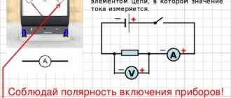
How the scheme works. The input (pins 3 and 4, observe polarity!) is supplied with control voltage from a 24V source. It is supplied through a control circuit, which is represented as a NO contact. This contact can be a regular relay, a controller output, or a sensor with a relay output or a PNP-type transistor output.
I wrote in detail about NO contacts and PNP outputs of sensors in this article. Highly recommend!
I remind you once again -
NC are closed (closed) contacts through which current flows in the normal position (without activation by a control signal).
BUT are open (unclosed) contacts through which in the normal position (without activation by a control signal) no current flows.
The conditional output contacts of the SSR will also be NO, because without activation of the control circuit, the load is turned off.
Now let's take a closer look at managing solid state drives.
SamElectric.ru on social networks
Subscribe! It's interesting there too!
Practical application of devices
The scope of use of solid-state relays is quite extensive. Due to their high reliability and lack of need for regular maintenance, they are often installed in hard-to-reach places on equipment.
In many relays, connecting the control circuit wires requires polarity, which must be taken into account during equipment installation
The main areas of application of TTP are:
- thermoregulation system using heating elements;
- maintaining stable temperatures in technological processes;
- control of transformers;
- lighting adjustment;
- diagrams of motion sensors, lighting, photo sensors for street lighting, etc.;
- electric motor control;
- uninterruptible power supplies.
With the increasing automation of household appliances, solid-state relays are becoming increasingly common, and developing semiconductor technologies are constantly opening up new areas of their application.
If desired, you can assemble the solid-state relay yourself. Detailed instructions are presented in this article.
Reversing solid state relays
There are also special three-phase solid-state relays for reversing motors that have two control inputs.
An example of turning on a three-phase relay is in the photo below:
Turning on a three-phase solid state relay
As you can see, the relay is not entirely three-phase; one phase is constantly supplied to the motor, which can cause danger.
Its connection diagram is printed on the relay body, where everything is clear. The relay is reversible, and it has two inputs - Forward and Reverse (Forward/Back). To reverse, phases L1 and L2 are swapped.
Important - there is no blocking inside the relay from simultaneous activation in both directions, and it must be provided in hardware (locking contacts of buttons/relays) and software (if control is from the controller). If this is not provided for, then a situation is likely where power outputs 1, 2, 3, 4 will be short-circuited