A transformer is a device that is designed to convert network electricity. This installation has two or more windings. During their operation, transformers can convert the frequency and voltage of the current, as well as the number of phases of the network.
During the performance of specified functions, power losses are observed in the transformer. They affect the initial amount of electricity that the device produces at the output. What are the losses and efficiency of a transformer will be discussed further.
Device
A transformer is a static device. It runs on electricity. There are no moving parts in the design. Therefore, an increase in energy costs due to mechanical reasons is excluded.
When operating power equipment, electricity costs increase during non-working hours. This is due to the increase in active no-load losses in steel. In this case, a decrease in the nominal load is observed with an increase in reactive type energy. Energy losses, which are determined in the transformer, relate to active power. They appear in the magnetic drive, on the windings and other components of the unit.
Transformer power losses
The efficiency of a transformer never reaches 100% because there are always electrical losses.
Losses in transformers are usually divided into two types: losses in copper (copper turns of windings) and losses in steel (core material). Copper losses occur due to the intrinsic resistance of the copper conductor. The current flowing through the winding causes a certain voltage drop, which is a loss of power. In this case, electrical energy is converted into thermal energy, which heats the winding.
Losses in steel, in turn, consist of losses caused by eddy currents and caused by cyclic magnetization reversal (hysteresis).
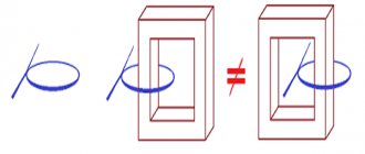
Eddy currents arise in a conductor that is in an alternating magnetic field. These conditions are satisfied by a steel core on which copper turns are wound. Eddy currents constantly arise in it, the magnitude of which can reach quite large values, due to which, in turn, the core heats up.
The amount of losses caused by the need for cyclic magnetization reversal is determined primarily by the quality of the steel from which the core is made. The core seems to contain a large number of dipoles, which, under the influence of an alternating magnetic field, periodically change their direction (rotate with the frequency of changes in the magnetic field). During the spatial change in the position of the dipoles, mechanical friction forces arise between them, which causes additional heating of the core. In this way, magnetic energy is converted into thermal energy (power loss due to hysteresis).
To reduce these losses, a number of measures are being taken. Losses caused by cyclic magnetization reversal can be reduced by using a special structured soft magnetic material for the core (electrical steel). Such a material has high magnetic permeability, but at the same time low coercive force.
To reduce losses in copper, an increase in the cross-section of the conductors of both windings is used, while their electrical resistance decreases. On the other hand, this causes an increase in the cost and weight of the transformer, so a cross-section that does not cause noticeable heating of the windings is considered sufficient.
To reduce eddy currents, the core is not made in the form of a single monolithic block, but is assembled from many electrically insulated plates. The thickness of each of them can be only a few tenths of a millimeter. Also, the electrical conductivity is greatly reduced by the alloying element specially introduced into the steel—silicon.
The integrated use of measures to reduce power losses makes it possible to increase the efficiency of transformers to 85-90%.
Concept of losses
When the installation is operating, part of the power is supplied to the primary circuit. It dissipates in the system. Therefore, the incoming power to the load is determined at a lower level. The difference is the total reduction in power in the transformer.
There are two types of reasons due to which the energy consumption of equipment increases. They are influenced by various factors. They are divided into the following types:
- Magnetic.
- Electrical.
They should be understood in order to be able to reduce electrical losses in the power transformer.
Magnetic losses
In the first case, losses in the steel of the magnetic drive consist of eddy currents and hysteresis. They are directly proportional to the mass of the core and its magnetic induction. The iron itself, from which the magnetic drive is made, affects this characteristic. Therefore, the core is made of electrical steel. The plates are made thin. Between them lies a layer of insulation.
Also, the reduction in power of a transformer device is affected by the frequency of the current. As it increases, magnetic losses also increase. This indicator is not affected by changes in device load.
Electrical losses
A decrease in power can be detected in the windings when they are heated by current. In networks, such costs account for 4-7% of the total energy consumed. They depend on several factors. These include:
- Electrical load of the system.
- Configuration of internal networks, their length and cross-sectional size.
- Operating mode.
- Weighted average power factor of the system.
- Location of compensation devices.
Power losses in transformers are variable. It is influenced by the square of the current in the circuits.
Example_calculation_of_losses_in_transformer
7. Calculation of power losses in a transformer
Power losses in transformers consist of active and reactive power losses.
Active power losses consist of two components: losses for heating the transformer windings, depending on the load current, and losses for heating the steel, depending on the load current.
Reactive power losses consist of two components: losses caused by magnetic flux dissipation in the transformer, depending on the square of the load current, and losses for magnetization of the transformer, independent of the load current, which are determined by the no-load current.
Calculation of power losses in a transformer is necessary for a more accurate selection of high-voltage networks, as well as for determining the cost of electricity.
We determine the active power losses in the transformer ΔP, kW, using the formula
where Pkz is the active power loss in the transformer during a short circuit experiment
Рхх – losses of active power in the transformer during the no-load test, kW.
ΔP = 7.3 · 0.6 2 +2 = 4.6 kW.
We calculate reactive power losses in the transformer ΔQ, kvar
where Uk.z. – voltage during short circuit experience as a percentage of the nominal
Iх.х. – current during idling experience as a percentage of the nominal
ΔQ = 0.01 · (5.5 · 0.6 2 +3) · 630 = 31.4 kVar.
Determine the total power loss in the transformer ΔS, kVA
ΔS = ,
ΔS = = 31.7 kVA.
We summarize all the data obtained in Table 4.
Table 4 - Power losses in the transformer
| Transformer type |
So, power losses in a transformer will depend on the load factor of the transformer, on its design and total rated power. To reduce losses, it is necessary to select the transformer correctly and load it optimally.
8. Calculation and selection of networks with voltages above 1 kV
The criterion for choosing the cross-section of cable lines is the minimum of the given costs. In the practice of designing lines for mass construction, the choice of section is made not according to comparative technical and economic calculations in each specific case, but according to standardized general indicators.
Because networks with voltages above 1 kV are not included in the list [4, clause 1.3.28], then the choice of networks to the workshop transformer substation is carried out according to the economic current density jek, . We calculate the maximum active power passing through the high-voltage cable, Рm(10), kW s taking into account power losses in the transformer
We determine the maximum reactive power passing through the cable U=10 kV, taking into account power losses in the transformer Qm(10), kVar, using the formula
We determine the total power in high voltage networks Sm(10), kVA
Sm(10)= =783.6 kVA.
We calculate the coefficients of active (cosφ(6)) and reactive (tgφ(6)) power of the high-voltage line
cosφ(10)= = 0.94,
tgφ(10)= = 0.37.
We calculate the current passing through a line with voltage U=10 kV Im(10), A
Im(10)= =22.6 A.
Using the reference book [4, table 1.3.36], we determine the economic current density, taking into account that the number of hours of use of the maximum load per year Tm = 3000-5000 thousand hours/year and the cable being laid is AAShv
We determine the economically feasible cable cross-section Fek, mm 2
Fek=,
Fek= =16.14 mm 2.
We accept for installation the cable of the nearest standard cross-section 16 mm 2, i.e. AAShv 3x16 with permissible current Id, A, determined from the catalog [4, table 1.3.16]
We determine the permissible current value taking into account correction factors
where Kp is the correction factor for parallel laying of two cables
in a trench, accepted according to the catalog according to [4, table 1.3.26], Kp=0.9;
Kt – correction factor for ground temperature, adopted according to catalog [4, table 1.3.3], Kt=1, because temperature t=15 ºC is accepted.
Calculation method
Losses in transformers can be calculated using a certain method. To do this, you will need to obtain a number of initial characteristics of the transformer. The technique presented below is used for two-winding varieties. For measurements you will need to obtain the following data:
- Nominal system power (NM).
- Losses determined at no-load (idle) and rated load.
- Short circuit losses (SCL).
- The amount of energy consumed over a certain amount of time (PE).
- The total number of hours worked per month (quarter) (OH).
- Number of hours worked at rated load level (LF).
Having received this data, the power factor (cos φ angle) is measured. If the system does not have a reactive power meter, its compensation tg φ is taken into account. To do this, the dielectric loss tangent is measured. This value is converted to power factor.
Transformer losses. Idling losses. Short circuit losses.
Transformer losses are energy losses that occur in the magnetic system, that is, in the steel of the transformer. And electrical losses arising in the windings of the transformer. There are no mechanical losses in the transformer because it has no moving parts. Consequently, electrical energy is not converted into mechanical energy. Transformer steel losses are determined using no-load testing. That is, the load is not connected to the secondary winding of the two winding transformers. The peculiarity of these losses is that they do not depend on the load mode of the transformer. That is, the no-load current is divided into two components. The first goes to create a magnetic flux penetrating the secondary winding. And the second is spent on losses in steel. These losses are caused by eddy currents in the core. Energy is also spent on hysteresis.Formula 1 - idle losses
where Pg hysteresis losses Pin eddy current losses I current in the primary winding r resistance of the primary winding Regardless of how the transformer load changes, the magnetic flux remains unchanged. And, therefore, the magnetizing current does not change. Losses in the core are also unchanged, since they depend on the grade of steel from which the core is made. Electrical losses are determined using a short circuit experiment. To do this, a reduced voltage is supplied to the primary winding of the transformer. The magnitude of this voltage is selected based on the fact that. When there is a short circuit in the secondary winding, a current of the rated value for a given transformer flows in the primary. Consequently, the currents will not exceed the rated ones and damage to the transformer will not occur.
formula 2 - Short circuit losses
where B is the load factor of the transformer. In this case, all energy is spent to cover losses in the windings. Since the voltage on the primary winding is small, the induction is significantly lower than the rated value and, therefore, losses in the core can be neglected. Losses in the windings depend on the load mode of the transformer. The greater the load, the higher the currents flowing in the wire, therefore, the losses will also be higher. There is another type of loss. They are caused by stray fields from the windings. This field permeates the design details of the transformer, the device body or fastening elements. At the same time, eddy currents arise in them, heating them.
formula 3 - total losses in the transformer
Calculation formula
The load factor in the presented methodology will be determined by the following formula:
K = Ea/NM*OC*cos φ, where Ea is the amount of active electricity.
What losses occur in the transformer during the loading period can be calculated using the established methodology. For this, the formula is used:
P = XX * OCH * PKZ * K² * LF.
Calculation for three-winding transformers
The methodology presented above is used to evaluate the performance of two-winding transformers. For equipment with three circuits, it is necessary to take into account a number of other data. They are indicated by the manufacturer in the passport.
The calculation includes the rated power of each circuit, as well as their short circuit losses. In this case, the calculation will be made according to the following formula:
E = ESN + ENN, where E is the actual amount of electricity that passed through all circuits; ESN – medium voltage circuit electricity; ENN – low voltage electricity.
Calculation example
To make it easier to understand the presented methodology, you should consider the calculation using a specific example. For example, it is necessary to determine the increase in energy consumption in a 630 kVA power transformer. It is easier to present the source data in the form of a table.
| Designation | Decoding | Meaning |
| NN | Rated voltage, kV | 6 |
| Ea | Active electricity consumed per month, kWh | 37106 |
| NM | Rated power, kVA | 630 |
| PKZ | Transformer short circuit loss, kW | 7,6 |
| XX | No-load losses, kW | 1,31 |
| VERY | Number of hours worked under load, h | 720 |
| cos φ | Power factor | 0,9 |
Based on the data obtained, a calculation can be made. The measurement result will be as follows:
K² = 4.3338
P = 0.38 kW*h
The % loss is 0.001. Their total number is 0.492%.
Measuring efficiency
When calculating losses, the efficiency indicator is also determined. It shows the ratio of the active type power at the input and output. This indicator is calculated for a closed system using the following formula:
Efficiency = M1/M2, where M1 and M2 are the active power of the transformer, determined by measurements on the input and output circuits.
The output is calculated by multiplying the rated power of the installation by the power factor (cosine of the angle j squared). It is taken into account in the above formula.
In transformers 630 kVA, 1000 kVA and other powerful devices, the efficiency indicator can be 0.98 or even 0.99. It shows how efficiently the unit operates. The higher the efficiency, the more economically energy is consumed. In this case, energy costs during equipment operation will be minimal.
Having considered the methodology for calculating transformer power losses, short circuits and no-load, it is possible to determine the cost-effectiveness of the equipment, as well as its efficiency. The calculation method involves using a special calculator or performing calculations in a special computer program.