Selecting the cross-section of wires and cables based on economic current density
Today we will consider such a concept as economic current density, we will analyze the requirements of the PUE for choosing the cross-section of wires and cables according to the economic current density, we will learn the physical and economic meaning of the concept of economic current density when choosing the cross-section of cables.
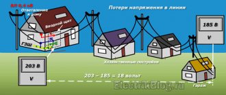
Any consumer wants to receive electricity at the lowest cost. The cost of electricity directly depends on the cross-section of wires and cables of electrical networks. If the cross sections are underestimated, then electricity losses in the networks will increase, and this will lead to an increase in the cost of 1 kWh. With increased cross-sections of supply lines, electricity losses will be less, but the initial investment in network construction will increase.
The cross section that corresponds to the minimum cost of electricity transmission is usually called economic.
It is not so easy to mathematically determine the economic cross-section of the conductors of wires and cables.
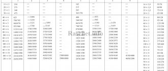
According to the PUE, the economic cross-section of wires and cables should be determined depending on the economic current density (Chapter 1.3):
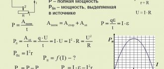
S=Imax/Jek
where Imax is the calculated current per hour of maximum power system, A;
Jek is the normalized value of economic current density, A/mm2, for given operating conditions, selected from the table. Jek depends on the material and the time of use of the maximum load.
The calculated current is taken in normal mode, without taking into account emergency overloads. The resulting section is rounded to a larger standard section.
Table 1.3.36 (PUE) - Economic current density.
| Conductors | Economic current density, A/mm2, with the number of hours of maximum load use per year |
| more than 1000 to 3000 | more than 3000 to 5000 | more than 5000 |
| Bare wires and buses: |
| copper | 2,5 | 2,1 | 1,8 |
| aluminum | 1,3 | 1,1 | 1,0 |
| Cables with paper and wires with rubber and polyvinyl chloride insulation with conductors: |
| copper | 3,0 | 2,5 | 2,0 |
| aluminum | 1,6 | 1,4 | 1,2 |
| Cables with rubber and plastic insulation with cores: |
| copper | 3,5 | 3,1 | 2,7 |
| aluminum | 1,9 | 1,7 | 1,6 |
According to the rules for electrical installations based on economic current density, the following are not selected:
- networks of industrial enterprises and structures with voltage up to 1 kV with the number of hours of use of the maximum load of enterprises up to 4000-5000;
- branches to individual electrical receivers with voltages up to 1 kV, as well as lighting networks of industrial enterprises, residential and public buildings;
- networks of temporary structures, as well as devices with a service life of 3-5 years.
From my experience, I can say that 0.4 kV networks are not checked for economic current density; it is enough to select based on the heating of the conductors and the permissible voltage drop, as well as perform protection against short-circuit currents.
1.3.29
When using the table. 1.3.36 the following must be followed (see also 1.3.27):
1. At maximum load at night, the economic current density increases by 40%.
2. For insulated conductors with a cross-section of 16 mm or less, the economic current density increases by 40%.
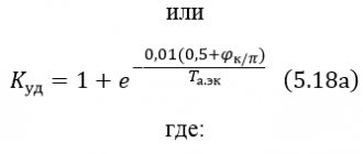
3. For lines of the same cross-section with branching loads, the economic current density at the beginning of the line can be increased by a factor, and is determined from the expression
WEBSOR Electrical Information Territory
- Basics Electrical safety Effect on humans
- Protective measures
- First aid
- Electrical safety in installations up to 1000 V with solidly grounded and insulated neutral
- Protective equipment High voltage indicator UVNU-10SZ IP
- Low voltage indicator ELIN-1-SZ
- Claws of KRPO
Theoretical foundations of electrical engineeringElectrical processes in vacuum and gasesThermionic emission of metals
Thermionic emission of an oxide cathodeElectrostatic electron emissionPhotoelectron emissionSecondary electron emissionElectronic emissionPassage of current in a vacuumCollision of electronsElectron movementTypes of electrical dischargeDark dischargeGlow dischargeArc dischargeGas plasmaCorona, spark and high-frequency dischargesMeasuring quantitiesUnits of electrical quantities
Characteristics of fundsElectric meter TsE6803VMMegaohmmeterElectrical materialsClassification of substances by electrical properties
Dielectrics Classification of dielectricsPolarization of dielectricsElectrical conductivity of dielectricsBreakdown of dielectricsElectrical strength of air gapsDischarge on the surface of a solid dielectricDischarge in oilSemiconductor materialsElectrical conductivity of semiconductors
Preparation and properties of semiconductorsCharacteristics of semiconductor materialsConductor materialsCopperAluminumProblems and answersElectric machinesDefinitions and requirements Rated modes and nominal values
General definitionsTechnical requirementsPower loss and efficiencyWinding designationRated rotation speeds of electric machinesAC Electrical MachinesDesign of 3-phase asynchronous and synchronous machines
Machine constant, electromagnetic loadsArmature windings and field windingsElectromotive and magnetizing forcesSquirrel cage type windingsActive winding resistancesWinding inductanceAsynchronous machinesActive and inductive resistance of windings
Magnetic circuit calculationBasic equations, equivalent circuits and phasor diagramBasic energy relationships and mechanical characteristicsLosses and efficiencyPie chart, performance characteristicsDetermination of the main dimensions of enginesProblems with the asynchronous motorTheorySynchronous machinesDC machinesTransformersTransformersCurrent repairs of TM transformersPower transformers type TM(G) and TMPN(G)Transformers TMG11 and TMGSU11Transformers TMG12Transformers TMG21Transformers OM, OMP, OMGTransformers TSGL, TSZGLTransformers TS, TSZParallel operation of transformersVoltage loss in transformerTransformer winding connection groupsTransformer faultsTransformer oilMotor protectionEquipmentElectrical equipment protection
Modular devices Automatic switchesCharacteristics automatic. off Residual current devices (RCDs)Selection and application of RCDReasons for tripping the RCDDifferential automatic. off Load switchesModular contactorsSurge suppressorAdditional devicesElectronic timerElectrical switchboard equipmentPower boards Input and distribution devices ASU
Low voltage switchgearDistribution points PRShRS power distribution cabinetsShield panels ShchO 70Floor boards ShchEControl boxesElectricity metering cabinets SHUELighting boards OSCHV, UOSCHVBoxes and cabinets AVR, blocks and control panels BU, PUAutomatic switchboards ShchAPRemote type metering boardShields for household needsVUA input deviceElectrical panel housingsDistribution boards ShchRN, ShchRV
Accounting and distribution boards SCHRUNBoards with mounting panel ShchRNM, ShchMPFloor distribution device URMSBlock-type floor distribution device UERBHousing for floor switchboardPanels for installing a single-phase PU meterFloor cabinetsASU framesAll-welded cabinetsExternal lighting cabinet SHNOExternal lighting control cabinetElectrical installation productsBoxes Installation boxes in solid walls
Installation boxes in hollow wallsJunction boxes in solid wallsJunction boxes in hollow wallsOpen mounted cable entry boxesBoxes for monolithic constructionBoxes for open installation with terminal block, zero busInstallation featuresPipesTraysElectrical boxesTire zeroConnectors, branch clamps, lugsTies (clamps)Heat shrinkable tubesElectrical installation devicesRequirements for installation of electrical installation devicesRequirements for electrical equipment of bathtubs and showersWire and cableMarking and characteristics
Cable productionAPPENDIX for cable products APPENDIX (stationary installation)APPLICATION (non-stationary installation)APPENDIX (power wires)APPENDIX (wires for various purposes)Wire selectionConnecting wiresTips for choosing a cableCable sleevesCircuit breakersVA-99VA-99MVA-99SVA-45VA selectionADFAVMContactorsSmall-sized contactors KME
Small-sized contactors KMIKMI contactors in a shellKTI series contactorsKT series contactorsPRK series startersApplication of contactorsEquipment phasingWe carry out ALL electrical installation workNormsGOSTs, reference information, rules
All about groundingClassification of premisesElectrical requirementsCharacteristics of conductor and insulating materialsGOST, SNiP, SP, TU Contents according to regulatory documentsSNiP 3.05.06-85 Electrical devicesGOST 10434-82 Electrical contact connectionsGOST 12.1.030-81 SSBT Electrical safetyGOST 13781.0-86. Couplings for power cables for voltages up to 35 kV GOST 11677-85. Power transformers GOST 14695-80 (ST SEV 1127-78). Complete transformer substations GOST 9.032-74. Paint and varnish coatings Data for calculating the lighting networkFourier series expansionCode of Practice for Design and ConstructionTechnical specifications for SIPElectrical wiringLaying cables up to 35 kVSubstationComplete transformer substations Nomenclature of package transformer substations
Substation equipmentSwitches, power boxesDisconnectors PE-19Disconnectors RC630 A disconnectorsTiresKSO-366, KSO-272, KRUInsulatorsDisconnectors RVTechnical description of disconnectorsFuses up to 1000VHigh voltage fusesDrives for switches with voltage 3-10 kVTechnical description of the PPV-10 driveVacuum circuit breakersVRVROVR1BP1 for CSRHRV3AN5VGG-10CSR camerasKSO 298AT, KSO 298AT-M, KSO 292AT, KSO 285AT, KSO 272AT, KSO 2(UMZ)ATKSO 366AT, KSO 366AT-VKSO 393AT, KSO 393AT-MCSR "Novation"Switchgear "Classic" series D-12PTSwitchgear series "Etalon"KSO-298 “STANDARD”KSO-298 RUELTASwitchgear series R-40 (35 kV)Surge suppressors 6(10) kVOil switchTechnical description of VPMVMP-10VMG-133Autogas load switch VNASwitch imageElectrical equipment repairOperation and repair of electrical equipment of the reactor plant
Repair of oil switchesRepair of switchgear contact partsRepair of PP-67 oil switch driveFeatures of the design and repair of the PPV (PPO) driveFeatures of the design and repair of the PE-11 driveIncreasing the reliability of MV, MV drivesAdjusting the spring drive winding device
Adjusting the spring drive activation mechanismSetting up the spring drive release mechanismAdjustment of MV with spring driveAdjustment of MV with electromagnetic driveImproving the reliability of VMP-10 and VMG-133Reactive power compensation unitsGeneral information about UKRM
UKRM 0.4 kVUKRM 6(10) kVSelecting the location of supply substationsElectricity supplyPower supply concept Electricity distribution
Power supply for administrative buildingsElectrical supply for residential buildingsWiringLoad calculationDesign loads of industrial enterprises
Design loads of residential and public buildingsPermissible current loads on wires and cablesSelection of maximum current line protectionSelection of sections based on permissible voltage lossActive and inductive line resistances
Network calculation based on permissible voltage loss without taking into account inductive reactanceNetwork calculation based on voltage loss taking into account line inductanceNetwork calculation using auxiliary tables of specific voltage lossesExamples of calculations of wire and cable cross-sections based on permissible voltage lossCalculation of the network based on the condition of the lowest metal consumptionCalculation of the network based on the condition of constant current densityShort circuits in electrical systemsGeneral instructions for calculating short-circuit currents
Three-phase short circuitAsymmetrical short circuitsShort circuit with simultaneous phase breakDetermination of short-circuit currents for the selection of circuit breakersShort circuit currents from electric motorsSelection of conductors for resistance to short-circuit current.Checking the trigger conditions of the protective deviceSelection of wires based on economic current densityBuses and busbar trunking in power supply systemsCurrent distribution over the cross-section of non-ferrous metal busbars
Determination of active and reactive resistance of a busbarPower and voltage losses in busbar trunkingSelection of busbar cross-sectionsChecking the selected busbar sectionVibrations of busbars having a turnPower losses in networksTransients in electrical systemsMathematical description of transient processes
Transient processes under large short-term disturbancesRegimes under large disturbancesModes under small disturbancesImproving the capacity of electrical systemsVoltage regulationVoltage regulation in networks
Local voltage regulationInternal network overvoltagesOvervoltage and surge protection
Characteristics of insulation levels of 6-35 kV networksCharacteristics of internal overvoltagesLightingQuantities and units of illumination
Sources of lightArtificial lighting methodsCalculation and protection of lighting networksCalculation of lighting using the utilization factor and specific power methodCalculation of lighting using the point methodSpecial cases of lighting calculationsCalculation of quality lighting characteristicsOutdoor LightingDetailed calculation of the lighting networkBasic requirements and choice of illuminationSystems and types of lightingLighting controlLighting designRepair of lamps with fluorescent lampsSmart HouseAir lineDesign spans of overhead lines - 0.4 kVLinear fittings ENSTO for VLI 0.4 kVLinear fittings NILED for VLI 0.4 kVInputs of power lines up to 1 kV into premisesApplication of linear fittings on overhead lines 6-20 kVEquipment for overhead lines (Z)-6(10) kVDesign of overhead line - 6(10) kVViolations during installation of SIPInstallation of long-spark arresters RDIP at VLZ-10kVSteel structures for the construction of VLI-0.4 kV, VLZ-6(10) kVAnalogues of NILEDExample of calculation of VLI-0.4 kVGrounding devices for overhead line supportsUnits and details of connections of grounding conductors of 0.38-35 kV overhead lines