Drag coefficient cd examples
General
In general, it is not an absolute constant for a given body shape. This depends on the speed of the air flow (or, more generally, the Reynolds number). For example, a smooth sphere has a value that varies from high values for laminar flow to 0.47 for turbulent flow. Although the drag coefficient decreases with increasing , the drag force increases. cd{\displaystyle c_{\mathrm {d))}re{\displaystyle Re}cd{\displaystyle c_{\mathrm {d))}re{\displaystyle Re}
| c d | Paragraph |
| 0,001 | Laminar flat plate parallel to the flow ( ) Re<106{\displaystyle Re<10^{6)) |
| 0,005 | Turbulent flat plate parallel to the flow ( ) re>106{\displaystyle Re>10^{6)) |
| 0,0512 | , 2015 |
| 0,07 | Nuna 3 |
| 0,075 | Pac-car |
| 0,076 | Milan SL (one of the fastest practical velomobiles) |
| 0,1 | Smooth sphere ( ) rezn = 106{\displaystyle Re=10^{6)) |
| 0,47 | Smooth sphere ( ) rezn = 105{\displaystyle Re=10^{5)) |
| 0,81 | Triangular trapezoid (45°) |
| 0,9-1,7 | Trapezoid with triangular base (45°) |
| 0,14 | Fiat Turbina 1954 |
| 0,15 | Schlörwagen 1939 |
| 0,18 | Mercedes-Benz T80 1939 |
| 0,186-0,189 | Volkswagen XL1 2014 |
| 0,19 | Alfa Romeo BAT 7 1954 |
| 0,19 | General Motors EV1 1996 |
| 0,212 | Tatra 77A 1935 |
| 0,23 | Tesla Model 3, Audi A4 B9 (2016) |
| 0,23 | 2016 |
| 0,24 | Tesla Model S |
| 0,24 | Hyundai Ioniq |
| 0,24 | Toyota Prius (4th generation) |
| 0,25 | Toyota Prius (3rd generation) |
| 0,26 | BMW i8 |
| 0,26 | Nissan GT-R (2011-2014) |
| 0,26 | Toyota Prius (2nd generation) |
| 0,27 | BMW E39 5 Series (1995-2003, Germany) |
| 0,27 | Mercedes-Benz CLS-Class Type C257 |
| 0,27 | Nissan GT-R (2007-2010) |
| 0,27 | Chrysler 200 (2015-2017) |
| 0,28 | 1959 Alfa Romeo Giulietta Sprint Speciale |
| 0,28 | 1969 Dodge Charger Daytona and 1970 Plymouth Superbird |
| 0,28 | 1986 Opel Omega sedan. |
| 0,28 | Mercedes-Benz CLA-Class Type C 117. |
| 0,29 | Mazda3 (2007), Nissan 350Z (Track and Grand Touring models) |
| 0,295 | Bullet (does not come to life, at subsonic speed) |
| 0,3 | Saab 92 (1949), Audi 100 C3 (1982), Fiat 500L (2012) |
| 0,31 | Maserati Ghibli (2013), 0.29 after restyling |
| 0,324 | Ford Focus Mk2/2.5 (2004-2011, Europe) |
| 0,33 | BMW E30 3 Series (1984-1993, Germany) |
| 0,34 | Ford Sierra (1982-1993), Saab 9000 (1984-1998) |
| 0,35 | Maserati Quattroporte V (M139, 2003–2012) |
| 0,36 | Citroen CX (1974-1991, France), Tesla Semi (2017, USA) |
| 0,37 | Ford Transit Custom Mk8 (2013, Türkiye) |
| 0,48 | Rough sphere ( ), Volkswagen Beetle = 106{\displaystyle Re=10^{6)) |
| 0,58 | (1997-2005) |
| 0,75 | Typical rocket model |
| 1.0 | Coffee filter, face up |
| 1.0 | road bike plus cyclist, touring position |
| 1.0–1.1 | Skier |
| 1,0–1,3 | Wires and cables |
| 1,0–1,3 | Adult (vertical position) |
| 1.1-1.3 | Ski jumper |
| 1.2 | Usain Bolt |
| 1,28 | Flat plate perpendicular to flow (3D) |
| 1,3–1,5 | Empire State Building |
| 1.4 | Formula 1 car |
| 1,8–2,0 | Eiffel Tower |
| 1,98–2,05 | Long flat plate perpendicular to flow (2D) |
Dependence of electrical resistance on the cross-section, length and material of the conductor
The resistance of various conductors depends on the material from which they are made.
You can check this practically using the following experiment.
Figure 1. Experience showing the dependence of electrical resistance on conductor material
Let's select two or three conductors from different materials, possibly smaller, but with the same cross-section, for example, one is copper, another is steel, the third is nickel. a and b to the bar at a distance of 1-1.5 m from one another (Fig. 1) and connect the battery to them via an ammeter. Now, alternately between clamps a and b , we will turn on first the copper, then the steel and, finally, the nickel conductor for 1-2 seconds, observing in each case the deflection of the ammeter needle. It will not be difficult to notice that the largest current will flow through the copper conductor, and the smallest - through the nickel conductor.
It follows from this that the resistance of a copper conductor is less than that of a steel conductor, and the resistance of a steel conductor is less than that of a nickel conductor.
Thus, the electrical resistance of a conductor depends on the material from which it is made.
To characterize the electrical resistance of various materials, the concept of so-called resistivity has been introduced.
Definition: Specific resistance is the resistance of a conductor with a length of 1 m and a cross-section of 1 mm 2 at a temperature of +20 C°.
Resistivity is denoted by the letter ρ (“rho”) in the Greek alphabet.
Each material from which a conductor is made has a certain resistivity. For example, the resistivity of copper is 0.0175 Ohm * mm 2 /m, i.e. a copper conductor 1 m long and 1 mm 2 cross section has a resistance of 0.0175 Ohm.
Below is a table of resistivities of materials most commonly used in electrical engineering.
Resistivity of materials most commonly used in electrical engineering
| Material | Specific resistance, Ohm*mm 2 /m |
| Silver | 0,016 |
| Copper | 0,0175 |
| Aluminum | 0,0295 |
| Iron | 0,09-0,11 |
| Steel | 0,125-0,146 |
| Lead | 0,218-0,222 |
| Constantan | 0,4-0,51 |
| Manganin | 0,4-0,52 |
| Nikelin | 0,43 |
| Tungsten | 0,503 |
| Nichrome | 1,02-1,12 |
| Fechral | 1,2 |
| Coal | 10-60 |
It is interesting to note that, for example, a nichrome wire 1 m long has approximately the same resistance as a copper wire about 63 m long (with the same cross-section).
Let us now examine how the dimensions of the conductor , i.e. length and cross-section, influence the value of its resistance.
Determination of the sliding resistance (friction) coefficient
The moment of force is... physical meaning, the condition of equilibrium of bodies, an example of a problem
DEFINITION
Resistance (friction) coefficient
called the coefficient of proportionality that connects the friction force () and the force of normal pressure (N) of the body on the support. Usually this coefficient is denoted by a Greek letter. In this case, we define the friction coefficient as:
We are talking about the sliding friction coefficient, which depends on the total properties of the rubbing surfaces and is a dimensionless quantity. The coefficient of friction depends on: the quality of surface treatment, rubbing bodies, the presence of dirt on them, the speed of movement of bodies relative to each other, etc. The friction coefficient is determined empirically (experimentally).
Calculation of resistance forces
In order to determine the resistance forces, the application of Newton's third law will be required. A quantity such as the resistance force will be numerically equal to the force that will need to be applied in order to uniformly move an object along a horizontal, flat surface. This becomes possible with the help of a dynamometer.
Finished works on a similar topic
- Coursework Resistance Forces 410 rub.
- Abstract Resistance forces 230 rub.
- Test work Resistance forces 190 rub.
Receive completed work or specialist advice on your educational project Find out the cost
Thus, the desired value turns out to be directly proportional to the mass of the body. It is worth taking into account that for a more accurate calculation it will be necessary to select a $u$ coefficient that depends on the material of the support. The material used to manufacture the research object itself is also taken into account. When calculating, the constant $g$ is used, whose value is 9.8 $m/s^2$.
When a body moves at a height, it is affected by the force of air friction, which depends on the speed of movement of the object. The required value is determined based on the following formula (suitable only for bodies moving at low speed):
$F = va$, where:
- $v$ – speed of movement of the object,
- $a$ is the resistance coefficient of the medium.
Measurement
How to calculate horsepower by engine size
There are at least two popular models for calculating rolling resistance.
- “Rolling Resistance Coefficient (RRC). The value of rolling resistance divided by the load on the wheel. The Society of Automotive Engineers (SAE) has developed test methods to measure tire RRC. These tests (SAE J1269 and SAE J2452) are usually performed on new tires. When measured using these standard test methods, most new passenger tires have RRC values ranging from 0.007 to 0.014." In the case of bicycle tires, values between 0.0025 and 0.005 are achieved. These coefficients are measured on rollers, with power meters on the road surface, or in coast-down tests. In the last two cases, it is necessary to subtract the effect of air resistance or carry out tests at very low speeds.
- The rolling resistance coefficient b
, which has the dimension of length, is approximately (due to the small angle of approach in) equal to the value of the rolling resistance force times the radius of the wheel divided by the wheel load. because(θ) = 1{\displaystyle \cos (\theta ) = 1} - ISO 18164:2005 is used for rolling resistance testing in Europe.
The results of these tests may be difficult for the general public to understand as manufacturers prefer to advertise "comfort" and "performance".
AC circuits
Resistance in networks with alternating current behaves somewhat differently, because Ohm's law is applicable only to circuits with constant voltage. Therefore, calculations should be done differently.
Impedance is denoted by the letter Z and consists of the algebraic sum of active, capacitive and inductive reactances.
When active R is connected to an alternating current circuit, under the influence of a potential difference, a sinusoidal current begins to flow. In this case, the formula looks like: Im = Um / R, where Im and Um are the amplitude values of current and voltage. The resistance formula takes the following form: Im = Um / ((1 + a * t) * po * l / 2 * Pi * r * r).
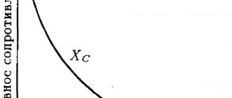
Capacitance (Xc) is due to the presence of capacitors in the circuits. It should be noted that alternating current passes through capacitors and, therefore, acts as a conductor with capacitance.
Xc is calculated as follows: Xc = 1 / (w * C), where w is the angular frequency and C is the capacitance of the capacitor or group of capacitors. Angular frequency is defined as follows:
- The frequency of the alternating current is measured (usually 50 Hz).
- Multiplies by 6.283.
Inductive reactance (Xl) - implies the presence of inductance in the circuit (inductor, relay, circuit, transformer, etc.). It is calculated as follows: Xl = wL, where L is the inductance and w is the angular frequency. To calculate inductance, you need to use specialized online calculators or a physics reference book. So, all the quantities are calculated using the formulas and all that remains is to write down Z: Z * Z = R * R + (Xc - Xl) * (Xc - Xl).
To determine the final value, it is necessary to extract the square root of the expression: R * R + (Xc - Xl) * (Xc - Xl). From the formulas it follows that the frequency of alternating current plays a big role, for example, in a circuit of the same design, as the frequency increases, its Z also increases. It must be added that in circuits with alternating voltage Z depends on the following indicators:
- Conductor lengths.
- Sectional area - S.
- Temperatures.
- Type of material.
- Containers.
- Inductance.
- Frequencies.
Consequently, Ohm’s law for a section of the chain has a completely different form: I = U / Z. The law for the complete chain also changes.
Stokes' law
Details about zero resistance filters
The mathematical study of the motion of bodies in a viscous fluid is associated with such great difficulties that until now only limiting cases have been accessible to such study, namely, the case of very high viscosity, i.e. very low Reynolds number, and the case of very low viscosity, i.e. very large Reynolds number. If viscous forces predominate in the flow, which occurs, on the one hand, in very viscous liquids (for example, in motor oil), and on the other hand, also in ordinary liquids with very small sizes that determine movement, then inertial forces can be neglected according to compared with viscous forces and assume that the pressure drop and frictional forces applied to any part of the liquid balance each other.
Cylindrical conductor resistance
A case of a pronounced surface effect.
The resistance of a cylindrical wire under alternating current is different from its resistance under direct current. This difference is due to the surface effect. At the same frequency, the surface effect will be more pronounced, the larger the wire diameter compared to Δ0.
Let us first consider the case of a strongly pronounced surface effect (thick conductor). Let along a cylindrical wire of radius a
a traveling current wave propagates.
Let us select a sufficiently small wire element of length l
, within which we can assume that the current amplitude does not change.
Let us assume that the radius of the wire a
significantly exceeds the penetration depth (
a
>> Δ0). In this case, you can use the results of the previous section to determine the wire resistance.
The complex resistance of a wire per unit length is determined by the formula:
(3.65)
where is the complex amplitude of the current in the wire, and –
complex voltage amplitude at the ends of a piece of wire of length
l.
Let's align the Z axis of the cylindrical coordinate system with the axis of the wire.
Then ,
(3.66)
Substituting expressions (3.66) into (3.65) and taking into account relations (3.61) and (3.62), we obtain:
(3.67)
Resistance Z can be expressed through active resistance R
and internal inductance
L
i per unit length of wire: .
Separating the real and imaginary parts in (3.67), we find R
and
L
:
(3.68)
From comparison of R
and
L
, with alternating current with their values and with direct current it follows that the ratio
R/ R
0 increases with increasing frequency, and the ratio
Li
/
Li
0, on the contrary, decreases.
The resulting formulas can be used only under the condition a>>Δ0. If this condition is not met, then in order to determine the resistance of the wire, you need to find its internal field.
The resistance of a wire taking into account its internal field.
Let us introduce a cylindrical coordinate system whose Z axis coincides with the axis of the isolated wire under consideration.
The complex amplitude of the current density in a wire can be represented as , where b is
a complex constant characterizing the propagation of a current wave (electromagnetic wave) along the wire.
Note that the constant b
is related to the propagation constant γ, used in electrical engineering, by the relation exp(- ibz) = exp(-γz) or b = -iγ.
It is known that the constant b
is close in absolute value to the wave number corresponding to the medium surrounding the wire.
The complex amplitude of the longitudinal component of the electric field strength inside the wire is written in a similar way: and the relation holds. The function satisfies the Helmholtz equation (2.31 from unit), in which we need to replace k
by .
Considering that we arrive at the equation: where . Since , a ,
then in the equation for we can assume that Writing the operator in a cylindrical coordinate system and taking into account that it does not depend on the angle φ, we arrive at a differential equation for the function:
This is the Bessel equation
. Its general solution has the form:
(3.69)
where and are the Bessel and Neumann functions of zero order, respectively, and A
and
B
are arbitrary constants.
At r
= 0 (i.e. on the axis of the wire) the function is limited and goes to infinity.
Therefore, in expression (3.69) you need to put B
= 0. To shorten the formulas, we introduce the notation . Expressing the constant
A
through and taking into account that when is a function, we obtain:
(3.70)
The complex linear resistance of a solitary wire is calculated using formula (3.65). In the complex amplitudes of voltage and current, an exponential factor can be distinguished: In this case, formula (3.65) takes the form:
(3.71)
Calculating and in accordance with the definitions of these quantities, we find:
Substituting the found values and into (3.71), we obtain:
(3.72)
This expression is valid for any frequency value or, which is essentially the same, for any relationship between the radius a
and penetration depth Δ°.
Let us first make sure that expression (3.72) as a>>Δ° transforms into formula (3.67). In a well-conducting medium (see Section 2.1.4), the parameter Therefore, when a>>Δ°, the inequality is satisfied. Consequently, the Bessel functions included in (3.72) can be replaced by the first terms of their asymptotic expansions for large values of the argument:
Substituting this expression into (3.72), we arrive at formula (3.67).
In the case of thin wires, for which a<<Δ°, the modulus of the argument of the Bessel functions Using the asymptotic representation of the Bessel functions for small values of the argument
we find:
(3.73)
The factor 1/(πа2σ2) in formula (3.73) coincides with the resistance of the conductor at direct current. Since, by assumption, a<<Δ°, the correction factor will be small compared to unity. As one would expect, the surface effect in this case is weak.
Note that the formulas obtained in this section for the linear resistance of a wire are correct in the case of a solitary wire. If a line consists of several parallel wires, then the current distribution over the cross-section of the wire cannot be considered axisymmetric. Taking into account the asymmetrical current distribution leads to an increase in linear active resistance. However, if the distance between the wires is significantly greater than the diameter of the wire, then the correction is small and can be neglected.
Ground reaction force
Let's imagine a very heavy object lying on a table. The table bends under the weight of the object. But according to the table, it acts on the object with exactly the same force as the object on the table. The force is directed opposite to the force with which the object presses on the table. That is, up. This force is called the ground reaction. The name of the force “speaks” the support reacts
. This force occurs whenever there is an impact on the support. The nature of its occurrence at the molecular level. The object seemed to deform the usual position and connections of the molecules (inside the table), they, in turn, strive to return to their original state, “resist.”
Absolutely any body, even a very light one (for example, a pencil lying on a table), deforms the support at the micro level. Therefore, a ground reaction occurs.
There is no special formula for finding this force. It is denoted by the letter , but this force is simply a separate type of elasticity force, so it can also be denoted as
The force is applied at the point of contact of the object with the support. Directed perpendicular to the support.
Since the body is represented as a material point, force can be represented from the center
Finding a Parameter
Finding resistance means calculating current losses. There are 2 fundamentally different approaches to calculation. In one case it is carried out for an electrical circuit, and in the other for a material. If in the second case everything is extremely clear, one formula is used, into which the dimensions of the body and the tabulated value of specific conductivity are substituted, then for an electrical circuit everything is not so simple.
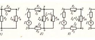
There can be 3 types of connection of elements in a circuit:
- Parallel. With such a connection, the circuit branches, that is, branches appear through which current flows. Branches may intersect with each other.
- Consistent. The connection diagram represents a single circuit in which there are no branches.
- Mixed. Consists of a combination connection, including combinations of parallel and serial connections.
Calculating resistance for each type of connection has its own characteristics. When connected in series, the total value is determined by simple addition: R = r1 + r2 +…+ rn. With a parallel connection, the total resistance of the circuit will be less than the smallest of the resistances of the branches. For such an inclusion the correct formula is: 1 / R = 1 / r1 + 1 / r2 +…+ 1 / rn.
The principle of calculating a mixed connection is based on grouping the electrical circuit according to the type of connection of the elements. The parameter determination is performed one by one. First, the resistance of one node, including the same type of connection, is calculated, then the next element is added to the result. This operation is repeated until one element remains.
In radio engineering, a part used as resistance is called a resistor. It is also used to designate the so-called equivalent parameter used in calculations of electrical circuits. It is entered if it is necessary to determine, for example, the power of the current source or the output voltage.
Thus, in order to correctly calculate resistance, several factors must be taken into account. In this case, you need to remember about the unified measurement system. SI should be followed. All quantities used in formulas must be entered in standard units of measurement. In almost all tables, the resistivity value is given in mm2/m, which is related to the area measurement.
Dependence on the curvature of the roadway
General
When a vehicle (car or railroad train) moves around a curve, rolling resistance generally increases. If the curve is not positioned to exactly counter the centrifugal force with an equal and opposite centripetal force due to the roll, then there will be a net unbalanced lateral force on the vehicle. This will result in increased rolling resistance. Banks are also known as "bang" or "jargon" (not to be confused with as). For railways, this is called curve resistance, but for roads it has (at least once) called rolling resistance due to curves.
Calculation of the resistance of series resistors
Current strength: formula
When the series resistance of several resistors is increased, the equivalent value increases accordingly. Calculation of the resistance of several elements connected in series is carried out by summing the ratings of each element. For example, when connecting several elements that are connected in one circuit in series, the amount of electrical resistance will be equal to the sum of the resistance level of each of the resistors. The formula is the same for any number of resistors.
How to find resistance formula for a series circuit
If you replace one of the elements in a series circuit, the level of resistance to the directed movement of particles in this circuit will change accordingly. This will also cause a change in current strength.
Resistor
Total resistance
Is the sum of all types of resistance forces:
X = X 0 + X i {\displaystyle X=X_{0}+X_{i}}
Since drag at zero lift is proportional to the square of the speed, and inductive drag is inversely proportional to the square of the speed, they make different contributions at different speeds. With increasing speed X 0 {\displaystyle X_{0}}
grows, and X i {\displaystyle X_{i}}
- falls, and the graph of the total resistance X {\displaystyle X}
on speed (“required thrust curve”) has a minimum at the intersection point of the curves X 0 {\displaystyle X_{0}}
and X i {\displaystyle X_{i}}
, at which both resistance forces are equal in magnitude. At this speed, the aircraft has the least drag for a given lift force (equal to weight), and therefore the highest
For the calculation, the constant g is used, which is equal to 9.8 m/s2. 3 How to calculate resistance if the body does not move in a straight line, but along an inclined plane? To do this, you need to enter the cos of the angle into the initial formula. It is the angle of inclination that determines the friction and resistance of the surface of bodies to movement. The formula for determining friction on an inclined plane will look like this: F=μ*m*g*cos(α). 4 If a body moves at a height, then it is acted upon by the force of air friction, which depends on the speed of the object. The required value can be calculated using the formula F=v*α. Where v is the speed of movement of the object, and α is the drag coefficient of the medium. This formula is only suitable for bodies that move at low speeds. To determine the drag force of jet aircraft and other high-speed units, another is used - F=v2*β.
Calculation of the resistance of parallel resistors
Resistor resistance - formula for calculation
The resistance formula for a parallel connection has a slightly different form.
Formula
With a relatively large number of serial elements, with an increase in the number of resistors in the circuit, the complexity of the calculation increases accordingly. Resistivity The letter that corresponds to it is the Latin ρ.
The use of parallel connection is justified in circuits in which a high parameter value is required. Then radioelements with the same power and resistance parameters are used. For example, 10 elements with a resistance level of 1000 Ohms, which are combined into a single circuit with a parallel connection, at the output will have an obstacle to the movement of charged particles of 100 Ohms.
Types of resistors
A resistor is an inert (passive) circuit element whose resistance can be either constant or variable. It depends on its design. It is used to regulate current and voltage in circuits, power dissipation and other restrictions. The literal translation from English of the word “resistor” is resist.
General view of the elements
Resistors can be classified according to the following criteria:
- purpose of the element;
- type of resistance change;
- material of manufacture;
- type of conductor in the element;
- VAC – current-voltage characteristic;
- installation method.
Devices are divided into general and special purpose elements. Special parts have increased characteristics of resistance, frequency, operating voltage or special requirements for accuracy.
The type of change in resistance divides them into constant and variable. Variable resistors are structurally different not only from elements having a constant resistance, but also from each other. They are different in design: there are adjusting and trimming ones.
Variable type adjusting elements are designed for frequent changes in resistance. This is part of the operation of the device circuit.
The tuning type is designed to fine-tune and adjust the circuit during initial startup. After this, the position of the regulator is not changed.
In the manufacture of resistive bodies (working surfaces), materials such as:
- graphite mixtures;
- metal film (oxide) tapes;
- wire;
- composition components.
Integral elements occupy a special place in this series. These are resistors made in the form of a pn junction, which is a zigzag channel integrated into the chip crystal.
Attention! Integral elements are always characterized by increased nonlinearity of their current-voltage characteristics. Therefore, they are used where the use of other types is not possible.
The type of current-voltage characteristic divides the elements under consideration into linear and nonlinear. The peculiarity of nonlinearity is that the component changes its resistance depending on the following characteristics:
- voltage (varistors);
- temperatures (thermistors);
- magnetic field level (magnetoresistors);
- illumination values (photoresistors);
- strain coefficient (strain gauges).
The nonlinearity of the current-voltage characteristic has expanded the possibilities of their application.
The installation method can be:
- printed;
- mounted;
- integrated.
In printed wiring, the pins of the part are inserted into a hole on the board and then soldered to the panel track. This installation method is automated, and soldering occurs by immersing the contact pads in a bath of solder.
Mounting is mostly done manually. The leads of the parts to be connected are first twisted together and then soldered to improve contact. The soldering itself is not designed to withstand mechanical stress.
Integrated assembly is carried out during the manufacturing process of microcircuit chips.
What is current-voltage characteristic
What a terrible name. The eyes are afraid, but the head remembers.
In simple terms, this is when voltage is dependent on the current flowing in an electrical circuit.
Also, this characteristic is divided into linear and nonlinear. What is the difference and what is it all about?
- Linear, just like nonlinear, is a chain.
- A linear circuit is one that contains voltage and current elements on which resistance depends.
- The nonlinear element is the dependence of the voltage at the terminals. It does not obey Ohm's law.
Types of resistance forces
There are several types of resistance force, differing in the nature of the impact on moving objects.
Rolling resistance force
The rolling resistance force is designated as Pf. In this case, strength is determined by several factors:
- the type and condition of the support along which the object moves;
- speed of body movement;
- air pressure and other environmental parameters.
The condition and type of the supporting surface determines the value of the rolling resistance coefficient, which is denoted f. If the temperature in the environment increases and the pressure increases, then this indicator will decrease.
Air resistance force
The force of air resistance or the magnitude of the frontal collision Pв is formed as a result of various pressure indicators. This characteristic directly depends on the intensity of vortex formation in front and behind a moving object. These parameters are determined by the shape of the moving body.
Note
The vortex formation in the front part of the object will have a greater influence on the drag force. If the flat-walled figure is rounded at the front and back, the resistance can be reduced to 72%.
The drag force can be calculated using the formula:
\($$P=cx\times p\times F_{b}$$\)
сх — streamlining or drag coefficient; p—air density; Fв is the drag area (midship section).
During translational motion, the mass of an object encounters resistance to acceleration, that is, acceleration. This force can be found using Newton's second law.
\($$Pj=m\times dVdt$$\)
where m expresses the mass of the moving object, and \(dVdt\) denotes the acceleration of the center of mass.
How to find friction
The resistance force can be determined by applying Newton's third law. In order for an object to move evenly along the support in the horizontal direction, a force must be applied to it that is commensurate with the resistance force. These values can be calculated correctly using a dynamometer. The drag force will be directly proportional to the mass of the object. More accurate calculations are made taking into account the u coefficient, which depends on the following factors:
- the material from which the support base is made;
- the material of which the moving body is composed.
When calculating the resistance force, use a constant value of g equal to 9.8 meters per centimeter squared. Moreover, if the movement of a body occurs at a certain height, it is affected by the force of air friction. This value depends on the speed at which the object is moving. The required value is determined using the following formula only under the condition that the object is moving at low speed:
\($$F=V\times a$$\)
where V is the speed of movement of the body, a is the drag coefficient of the medium.
Case Study
The tester is connected in series with the light source. Lighting fixture voltage = 220 Volts. Power unknown. The ammeter reading shows 276 milliamps of current. What is the size of the lamp coil when resistors are connected in series to the circuit?
Formula for finding spiral resistance
Electrical resistance is a physical quantity that corresponds to the degree to which each material obstructs the movement of electrical particles. It is possible to measure the level of a value with a multimeter. In this case, you will have to find the value using the formula. To prevent electrical current from reaching unintended areas, it is advisable to ground the transmission lines. This physical quantity is used in many radio components, for example, LEDs. In an electrical circuit, to find out the value, you need to connect phase and zero to a voltmeter at a known current strength, then calculate it using Ohm's law.
3.11. Motion resistance forces and power expended to overcome them
Resistance forces are forces that impede the movement of a car. These forces are directed against his movement.
Rice. 3.12. Resistance forces to vehicle movement
When driving on an incline characterized by height H
n, with the projection length
on
the horizontal plane and the elevation angle of the road α, the following resistance forces act on the car (Fig. 3.12): rolling resistance force
P
k, equal to the sum of the rolling resistance forces of the front (
P
k1) and rear (
P
k2) wheels, lifting resistance force
P
p, air resistance force P
vi and
.
Rolling and lifting resistance forces are related to the characteristics of the road.
The sum of these forces is called the resistance force of the road R
d
.
Rolling resistance force
The occurrence of rolling resistance during movement is due to energy losses due to internal friction in tires, surface friction of tires on the road and the formation of ruts (on deformable roads).
Energy losses due to internal friction in the tire can be judged from Fig. 3.13, which shows the relationship between the vertical load on the wheel and the deformation of the tire - its deflection f
w.
When a wheel moves on an uneven surface, the tire experiences a variable load and becomes deformed. Line ,
which corresponds to an increase in the load deforming the tire, does not coincide with the line
aO,
which corresponds to the removal of the load. The area of the region enclosed between the indicated curves characterizes the energy loss due to internal friction between the individual parts of the tire (tread, carcass, cord layers, etc.).
The energy loss due to friction in the tire is called hysteresis, and the OaO
- hysteresis loop.
Friction losses in a tire are irreversible, since during deformation it heats up and heat is released from it, which is dissipated into the environment. The energy expended on deforming the tire is not fully returned when its shape is subsequently restored.
Rolling resistance force P
reaches its greatest value when driving on a horizontal road. In this case
R
k
= f G
,
where G
is
the weight of the car, N;
f
is the rolling resistance coefficient.
Rice. 3.13. Energy losses due to internal friction in the tire:
A
- point corresponding to the maximum load and deflection values of the tire
Rice. 3.14. Dependences of rolling resistance force P
ki of power
Nk
required to overcome this resistance, depending on the speed of the car
When moving uphill and downhill, the rolling resistance force decreases compared to P k
on a horizontal road, and the steeper they are, the more significant they are. For this case of motion, the rolling resistance force is
P k
= f G
cos
α
,
where α
— elevation angle, °.
Knowing the force of rolling resistance, we can determine the power, kW, spent on overcoming this resistance:
N к
=
(
v f G
cos
α
)/1000,
where v
— car speed, m/s.
For a horizontal road cos 0° = 1 and
N k
=
(
vP
k)/1000 = (
v f G
)/1000.
Dependences of the rolling resistance force P k
and power
N to
the vehicle speed
v
are shown in Fig. 3.14.
Types of resistance in alternating electric current circuits.
⇐ PreviousPage 4 of 15Next ⇒
In alternating electric current, circuit elements have 2 types of resistance: active and reactive.
With each type of resistance, the energy of the electric current is converted into other types of energy.
Resistance is called active if the energy of the electric current is converted into heat.
Resistance is called reactive if current energy is converted into the formation of an electromagnetic field.
There are 2 types of reactance known.
Inductive reactance is the resistance resulting from the phenomenon of self-induction.
Inductive reactance
Where ω is the cyclic frequency of the current,
L is inductance.
Capacitance is the resistance that a capacitor offers to alternating current.
§ Alternator
is an electrical device designed to convert mechanical energy into alternating current energy.
The main parts of the generator are (Fig. 1):
§ inductor
- an electromagnet or permanent magnet that creates a magnetic field;
§ anchor
- winding in which an alternating EMF is induced;
§ commutator with brushes
- a device by means of which current is removed from rotating parts or supplied through them.
Rice. 1
The stationary part of the generator is called the stator
, and the movable one is
the rotor
. Depending on the design of the generator, its armature can be either a rotor or a stator. When receiving high-power alternating currents, the armature is usually made motionless in order to simplify the current transmission circuit to the industrial network.
Powerful generators produce a voltage of 15-20 kV and have an efficiency of 97-98%.
Operating principle
The operating principle of an alternating current generator is based on the phenomenon of electromagnetic induction.
Let a conducting frame of area S
rotates with angular velocity ω around an axis located in its plane perpendicular to a uniform magnetic field with induction
B
⃗ (see Fig. 1).
With uniform rotation of the frame, the angle α between the directions of the magnetic field induction vector B
⃗ and the normal to the plane of the frame
n
⃗ changes with time according to a linear law.
If at time t
= 0 the angle α0 = 0 (see Fig. 1), then
α
=
ω
⋅
t
=2
π
⋅
ν
⋅
t
,
where ω is the angular velocity of rotation of the frame, ν is the frequency of its rotation.
In this case, the magnetic flux passing through the frame will change as follows
Φ( t
)=
B
⋅
S
⋅cos
α
=
B
⋅
S
⋅cos
ω
⋅
t
.
Then, according to Faraday's law, an induced emf is induced
e
=−Φ′(
t
)=
B
⋅
S
⋅
ω
⋅sin
ω
⋅
t
=E
m
⋅sin
ω
⋅
t
.
We emphasize that the current in the circuit flows in one direction during half a turn of the frame, and then changes direction to the opposite, which also remains unchanged during the next half turn.
RMS values of current and voltage
§ Current (effective) force value
alternating current is the strength of such a direct current, which, passing through a circuit, releases the same amount of heat per unit time as a given alternating current.
Denoted by the letter I
.
§ Current (effective) voltage value
alternating current is the voltage of such direct current, which, passing through the circuit, releases the same amount of heat per unit time as the given alternating current.
Denoted by the letter U
.
In the contact network of electrified railways. d. Direct electric current with a voltage of 3 kV or alternating single-phase current of industrial frequency with a voltage of 25 kV . When powered by alternating current, the design of the rolling stock becomes more complicated, but the power supply devices for electric railways are significantly simplified , the distance between traction substations increases with the same losses to 50 km (20-25 km with direct current), the cost of constructing a contact network is reduced to 10%, in 2.5 times less copper consumption.
Ticket number 11
1 Mechanical work. Power.
If a force F acting on a body causes it to move s, then the action of this force is characterized by a quantity called mechanical work
(or simply
work
).
Mechanical work A is a scalar quantity equal to the product of the modulus of force F acting on the body and the modulus of displacement s performed by the body in the direction of action of this force, i.e.
A=Fs. (3.9)
In the case described by formula (3.9), the direction of movement of the body coincides with the direction of the force. However, more often there are cases when the force and displacement make an angle between themselves that is not equal to zero or α. (Fig. 30)
A=Fsсosα. (3.10)
Thus, in the general case, mechanical work is equal to the product of the force modulus and the displacement modulus by the cosine of the angle between the directions of force and displacement . The work of a force directed along the movement of a body is positive, and the work of a force directed against the movement of a body is negative. Using formulas (3.9) and (3.10), the work of a constant force is calculated. The unit of mechanical work is determined from formula (3.9). In SI, the unit of work is taken to be the work done by a force of 1 N when the point of its application is moved by 1 m. This unit is called the joule (J): 1 J = 1 N 1 m.
Power is a quantity that characterizes the speed of work. Power N
they call a value equal to the ratio of work A to the period of time t during which this work was performed:
N=A/t (3.11)
From formula (3.11) it follows that the SI unit of power is 1 J/s (joule per second). This unit is otherwise called watt (W), 1 W = 1 J/s.
We find the connection between power and speed during uniform motion by substituting (3.10) into (3.11):
N=Fvcosα.
(This formula is also valid for variable motion, if by N we mean instantaneous power, and by V we mean instantaneous speed). If the direction of the force coincides with the direction of displacement, then cosα=1 and N=F·v. From the last formula it follows that
F=N/v and v=N/F.
From these formulas it is clear that at constant engine power, the speed of movement is inversely proportional to the traction force and vice versa. This is the basis for the operating principle of the gearbox (gearbox) of various vehicles.
⇐ Previous4Next ⇒
Recommended pages:
Drag forces at high speeds
In the case when we are dealing with low speeds, the resistance will depend on:
- fluid viscosity;
- movement speed;
- linear dimensions of the body.
Let us consider the effect of the laws of friction at high speeds. Thus, the laws of viscous friction will have little application to air and, in particular, to water. Even with velocities as low as 1 cm/s, they will only be suitable for bodies of tiny sizes (in millimeters).
Note 2
The resistance experienced by a swimmer diving into the water will in no way be subject to the law of viscous friction.
When moving slowly, the liquid will smoothly flow around the object of movement. In this case, the resistance force that it will overcome will be the force of viscous friction.
Under conditions of high speed, a more complex fluid movement will occur behind the moving object. Different streams will begin to appear and disappear in the liquid, forming unusually shaped figures, vortices, and rings. Thus, the pattern of streams will be subject to constant changes. The occurrence of such a movement is called turbulent.
Turbulent drag will depend on the speed and size of the object differently than with viscous drag. So, it will be proportional to the squares of the speed and linear dimensions. With such movement, the viscosity of the liquid ceases to be of decisive importance, and its density becomes the determining property. Thus, the following formula is valid for the force $F$ of turbulent drag:
$F=pv^2L^2$, where:
- $v$– movement speed,
- $L$ – linear dimensions of the object,
- $p$ is the density of the medium.
Determination of friction force
Friction forces are determined using Newton's third law, according to which the resistance force is equal to the force with which it is necessary to act on a body in order to move it uniformly along a horizontal surface. It is measured using a dynamometer.
The value of the friction force is directly proportional to the mass of the body and the material of which it consists. You should also take into account the coefficient u, which depends on the material of the support surface. In addition, to calculate the friction force, the acceleration of gravity \(g=9.8 m⁄s^2\) is used.
Did not you find what you were looking for?
Just write and we will help
When a body moves high above the ground, the resistance forces depend on the density of the air and the speed of the body's movement. At a low speed of movement, the friction force is determined by the formula: \(F=va\), where \(v\) is the speed of movement of the body; \(a\) – air resistance coefficient.
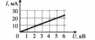
What is the voltage?
Voltage is directly related to current work, charge and resistance. To measure the voltage directly in an electrical circuit, you need to connect a voltmeter to it. It is connected to the circuit in parallel, unlike an ammeter, which is connected in series. The clamps of the measuring device are attached to those points between which the voltage needs to be calculated. For it to display the value correctly, you need to turn on the circuit. In the diagrams, the voltmeter is indicated by the letter V surrounded by a circle.
Image of a voltmeter and an electrical circuit
Voltage is denoted in Latin and measured in. It is equal to the work that the field does when moving a unit charge. The formula for current voltage is U = A/q, where A is the work done by the current, q is the charge, and U is the voltage itself.
Note! Unlike a magnetic field, where charges are stationary, in an electric field they are in constant motion. Electric field
Electric field
Formulation of Ohm's law
Ohm's law has the following formulation. To calculate resistance, you need to divide the voltage by the current in the electrical circuit. The physical quantity is determined by the number of free charged particles in the material.
What letter represents resistance? In the SI measurement system at the UN Congress, the Latin R (from the English resistance) was chosen as a symbol for recording a physical phenomenon.
Different degrees of magnitude are inherent in each material due to different concentrations of electric current carriers. The highest concentration is inherent in metals, which is why they are the best conductors. The peculiarity lies in the maximum number of conducting electrons, which are charged particles that do not belong to any elementary particle in the metal or other raw material. The emergence of current and, as a consequence, the movement of charged particles occurs under the influence of external electric fields.
Voltage divider
The most commonly used ready-made power supplies are designed for output voltages: 9, 12 or 24 volts. At the same time, most electronic circuits and devices use a supply voltage in the range from 3 to 5 V. In this case, there is a need to reduce the value of Upit to the required value. This can be done using a voltage divider, which has many options. The simplest one is a resistor divider.
Divider circuit made using resistors
Connecting an LED through a resistor and calculating it
Such voltage dividers are used exclusively in low-power circuits. This is due to their low efficiency. Some of the power from the power supply is dissipated on the divider, turning into heat. These losses are greater the more you need to reduce the initial voltage. Connecting a load in parallel to one arm requires that Rн be much larger than the resistor installed in this arm. Otherwise, the divider will produce unstable power.
With this scheme, the voltage is distributed over the arms of the divider according to the obtained ratios between R1 and R2. The magnitude of the resistance does not play a role in this case. But it should be remembered that at low values of R1 and R2 both the power at the load and the amount of losses due to heating of the elements increase.
Attention! Before you calculate the exact parameters, you need to remember how to select resistors. If they are equal, the output voltage is divided in half
If equality is not observed, the divided voltage must be removed from the element having a higher rating.
An example of a divider circuit using resistors with small and large values
Ohm's law for a complete circuit
Full chain
(in contrast to the section of the circuit, in relation to which we described everything above) is called
a circuit taking into account the current source
.
Why is it important?
Precisely because if we imagine an electrical circuit conditionally as a system of pipes for water, then a section of the circuit will be an open piece of pipe, and the complete circuit will be a looped system
.
From the example it may seem that a section of the circuit is an open circuit in the electrical sense. No, that's not what the example is for. Both there and there the electrical circuit is closed.
We just need to indicate that without taking into account the current source and its internal resistance (r), the circuit is not complete, and the calculation is not always able to take into account all significant characteristics.
Well, internal resistance
, as you probably guessed, is the resistance that the current source has. Yes, it is difficult for the current in the circuit to pass through the source itself! Even the source itself provokes energy losses. But it cannot be calculated similarly to the calculation for a section of a chain.
It turns out that internal resistance will also be added to Ohm’s law. That's all! It's OK.
The formulation of Ohm's law for a complete circuit will change slightly. Now we will replace the word voltage with the word EMF (electromotive force), and the word resistance will be replaced by the sum of the external resistance of the circuit and the internal resistance of the current source. Well, the formula will be like this:
Examples of problem solving
EXAMPLE 1
Exercise
The maximum speed of a car on a horizontal section of the road is equal to when its maximum power is equal to P. The drag coefficient of the car is C, and the largest cross-sectional area in the direction perpendicular to the speed is S. The car has undergone reconstruction, the largest cross-sectional area in the direction perpendicular to the speed has been reduced to a value, leaving the coefficient resistance unchanged. Consider the friction force on the road surface constant, find what is the maximum power of the car if its speed on a horizontal section of the road becomes equal to
The air density is .
Solution
Let's make a drawing.
We define the power of the car as: where is the traction force of the car. Assuming that a car on a horizontal section of the road moves at a constant speed, we write Newton’s second law in the form: In the projection onto the X axis (Fig. 1), we have: The resistance force that the car experiences while moving in the air is expressed as:
Then the power of the car can be written:
Let us express from (1.5) the friction force of the car on the road:
Let's write the expression for power, but with the car parameters changed according to the problem conditions:
Let's take into account that the friction force of the car on the road has not changed, and take into account expression (1.6):
Answer
EXAMPLE 2
| Exercise | What is the maximum speed of a ball that falls freely in the air if the following are known: the density of the ball (), the density of air (), the mass of the ball (), and the drag coefficient C? |
| Solution | Let's make a drawing. Let's write down Newton's second law for the free fall of a ball: |
Electrical resistivity
Resistivity is a parameter that determines the level of obstruction to the movement of electric current through a conductor of a certain length. Depends on the parameter of a particular substance, on the length. For a material with homogeneous properties and a known resistance value and conductor length, the specific parameter is calculated using the formula below.
Calculation of volumetric electrical resistivity
In fact, the meaning of the equation is as follows. Specific resistance is the amount of resistance when passing through a conductor of a certain length, with the same cross-sectional area throughout the entire route.
The parameter is measured in Ohm*meter. Thus, one Ohm*meter is equal to the level of obstacle to the directed movement of charged particles through a homogeneous conducting medium with a length of 100 cm and a cross-sectional area of 1 square meter.
Resistor calculation
To select and install elements in the circuit, you must first calculate the rating and power of the components.
Formula for calculating resistance and power
Current resistance: formula
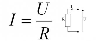
Use Ohm's Law for a section of the circuit to calculate the resistance of the resistor, the formula is:
R = U/I,
Where:
- U – voltage at the terminals of the element, V;
- I – current strength in a section of the circuit, A.
This formula is applicable for currents of constant direction. In the case of calculations for alternating current, the circuit impedance Rz is taken into account.
Important! The structure of the circuits is not limited to installing only one resistor. Usually there are many of them, they are connected to each other in parallel and in series
To find the general indicator, separate methods and formulas are used.
Serial connection
With this connection, the “output” of one element is connected to the “input” of another, they go sequentially one after another. How to calculate the resistor in this case? You can use an online electronic calculator, you can apply the formula.
The total value will be the sum of the resistances of the components included in the series connection:
R123 = R1+R2+R3.
Each of them will experience the same voltage drop: U1, U2, U3.
Parallel connection
When performing this type of connection, the terminals of the same name are connected in pairs, the formula looks like:
R = (R1 x R2)/ (R1 + R2).
Usually the resulting R value is less than the smaller of all the values of the connected elements.
Serial and parallel connections
Information. In practice, parallel or series connection is used when there is no part of the required rating. For such cases, elements are selected of the same power and the same type, so as not to get a weak link.
Mixed compound
It is possible to calculate the total resistance of mixed connections by applying the combining rule. First, all parallel and series connections are selected and equivalent equivalent circuits are drawn up. They begin to be calculated using formulas for each case. From the resulting simpler circuit, parallel and serial links are again isolated and calculations are made again. They do this until they get the most elementary compound or one equivalent element. The calculated result will be the desired one.
Calculation method for mixed connection
Calculation
The basic formula for finding the reading of a conductor can be calculated or represented as R=U/I, where U is the voltage difference across the conductor ends and I is considered the current that flows under the voltage difference. The resulting value is represented in Ohms.
You may be interested in this Insulation measurement
Note! In addition to the topic of how to determine the resistance of a resistor using the formula, you can also correctly calculate the required readings using a special measuring device called an ohmmeter or multimeter.
Formula used everywhere for calculation
When "resistance is futile"
Electric current is a smart and cunning guy. If it has the ability to bypass the resistor and follow a perfect conductor without resistance, it will do so. At the same time, this will not work with resistors of simply different values: it will not simply go through less resistance, but will be distributed according to Ohm’s law - more current will go where the resistance is less, and vice versa.
But in the figure below, the circuit resistance is zero, because no current will flow through the resistor.
Current follows the path of least resistance.
Now let's look at Ohm's law for a section of the circuit again.
| Ohm's law for a circuit section I = U/R I - current strength [A] U - voltage [V] R - resistance [Ohm] |
Let's substitute a resistance equal to 0. It turns out that the denominator is equal to zero, but in mathematics they say that you cannot divide by zero. But we will reveal a terrible secret to you, just don’t tell the mathematicians: you can divide by zero. If we completely simplify such a complex calculation (precisely because it is complex, we always say that it cannot be done), then we get infinity.
That is:
I = U/0 = ∞
This case is called a short circuit - when the magnitude of the current is so great that it can be directed to infinity. In such situations we see a spark, a storm, madness - and everything breaks.
This happens because two points in the circuit have a voltage between them (that is, there is a difference between them). It's like a waterfall suddenly appearing along a river. This difference causes a spark, which can be avoided by placing a resistor in the circuit.
It is in order to avoid short circuits that additional resistance is needed in the circuit.
Calculation of electrical conductor resistance
The resistance of an electrical conductor is calculated using the formula:
R = ρ * L / S
- R is the resistance of the electrical conductor
- ρ - conductor resistivity is calculated by formula (1): ρ = ρ20[1 + α(t - 20)] ρ20 - conductor resistivity at temperature t = 20°C (Table 1)
- t —conductor temperature
- α is the temperature coefficient of electrical resistance (Table 1)
How to find out the resistance of 1 meter of copper wire
After finding out all the factors that influence the resistance of a copper wire, you can combine them in the formula for the dependence of resistance on the cross-section of the conductor and find out how to calculate this parameter. The mathematical expression is as follows: R= pl/s, where:
- ρ—resistivity;
- l is the length of the conductor, when finding the resistance of a copper conductor 1 m long, l = 1;
- S—cross-sectional area.
You may be interested in this Features of the DRL 250 lamp
To calculate S, in the case of a cylindrical wire, the formula is used: S = π ∙ r2 = π d2/4 ≈ 0.785 ∙ d2, here:
- r is the radius of the wire section;
- d is its diameter.
If the wire consists of several cores, then the total area will be equal to: S = n d2/1.27, where n is the number of cores.
If the conductor has a rectangular shape, then S = a ∙ b, where a is the width of the rectangle, b is the length.
Important! You can find out the diameter of the section using a caliper. If it is not at hand, then wind the measured wire around any rod, count the number of turns, preferably there should be at least 10 for greater accuracy
After this, measure the wound part of the conductor and divide the value by the number of turns.
Calculation of cross-sectional area