Resistance
The current strength in a conductor depends not only on the voltage of the electric field in it.
It also depends on the conductor itself: on its shape, size, and on what material it is made of. At the same field voltage, the currents in different conductors will be different. Let's take a piece of copper wire 100 meters long with a cross-section of 4 square millimeters. Let's create a voltage of one volt at the ends. The ammeter will show in this case a current of 2.2 amperes.
At the same voltage, in the same piece of iron wire, the current will be only 0.44 amperes, and in the same wire, but made of nichrome (an alloy of nickel, iron and chromium) - only 0.03 amperes.
Copper, iron and nichrome have different electrical resistance. The resistance of copper is low, that of iron is greater, and that of nichrome is very high.
Resistance depends not only on the material of the conductor, but also on its shape and size. A thick wire has less resistance than a thin wire, and a long wire has more resistance than a short wire. To understand why this is so, we need to find out what causes the resistance of conductors to electric current. We will talk about this further.
The unit of resistance is the resistance of a conductor in which a voltage of one volt creates a current of one ampere. This resistance is called one ohm.
So, the current strength in a conductor depends on the field voltage at its ends and on the resistance of the conductor. The higher the voltage, the greater the current. The greater the resistance, the less current.
To find out what the current strength is, you need to divide the voltage created by the field at the ends of the conductor by the resistance of this conductor.
In practice, the current strength is usually not calculated, but measured with an ammeter. Voltage is also measured. And knowing the voltage and current, it is not difficult to calculate the resistance of the conductor.
Since voltage force current = voltage / resistance, THEN
resistance = voltage / current,
On the terminals of the arc lamp shown in Fig. 12, a voltage of 55 volts is created. A current of 5 amperes flows through the arc. This means that the resistance of the burning arc is equal to
55 / 5 = 11 ohms.
Not only metals, but also all other bodies have electrical resistance.
The resistance of insulators (quartz, rubber, glass, porcelain, etc.) is especially high. If there were absolutely no free charges (electrons, ions) in insulators, then their resistance would be infinite. The highest voltage would not cause current in the insulators.
In fact, such ideal insulators do not exist. In any insulator there is a small number of electrons and ions that have escaped from their places. Therefore, in insulators, when a field is applied, a current arises.
Advantages and disadvantages of resistance thermometers
Advantages of resistance thermometers
- High measurement accuracy (usually better than ±1 °C), can reach up to 13 thousandths of °C (0.013).
- Possibility of eliminating the influence of changes in the resistance of communication lines on the measurement result when using a 3- or 4-wire measurement circuit.
- Almost linear characteristic.
Disadvantages of resistance thermometers
- Relatively small measuring range (compared to thermocouples)
- Expensive (in comparison with thermocouples made of base metals, for platinum resistance thermometers of the TSP type).
- An additional power supply is required to set the current through the sensor.
We advise you to study Inductive Resistance
Types and properties of semiconductors
All semiconductors can be divided into several main types. Among them, the leaders are pure or proprietary materials, which do not contain any impurities.
They are characterized by a crystalline structure, where the atoms are arranged in a periodic order at its nodes. Here there is a stable mutual connection between each atom and four atoms located nearby. This makes it possible to form permanent electron shells, which contain eight electrons. At a temperature equal to absolute zero, such a semiconductor becomes an insulator, since all electrons are connected by covalent bonds. When the temperature increases or any irradiation occurs, electrons can escape from covalent bonds and become free charge carriers. When moving, the free spaces are gradually occupied by other electrons, so the electric current flows only in one direction.
In electronic semiconductors, in addition to the four atoms that form the basis of the crystal lattice, there are so-called donors. They are impurities in the form of pentavalent atoms. The electron contained in such an atom cannot normally enter into a covalent bond and is therefore separated from the donor. Thus, it turns into a free charge carrier. In turn, the donor becomes a positive ion, this can happen even at room temperature.
Hole semiconductors have a crystal lattice containing trivalent impurity atoms called acceptors. In such a lattice one covalent bond remains unfilled. It can be filled with an electron that has broken away from a neighboring bond. The impurity atom is transformed into a negative ion, and a hole appears in the place of the departed electron. That is, in this case, the one-way movement of the electric current also begins.
Factors affecting the resistance of semiconductors
It has been experimentally established that as the temperature increases, the electrical resistance in semiconductor crystals decreases. This is due to the fact that when the crystal is heated, the number of free electrons increases, and their concentration increases accordingly. The changing resistance of semiconductors under the influence of temperature is used to create special devices called thermistors.
In order to make a thermistor, semiconductors are used, which are oxides of individual metals in a mixed state. The finished substance is placed in a protective metal case with insulated terminals. With their help, the device is connected to the electrical circuit.
Thermistors are used to measure temperature or to maintain it in a given mode in any devices. The main principle of their operation is changing resistance with temperature changes. The same principle is used in photoresistors. Here the resistance value changes depending on the lighting level.
Operating principle of a resistance thermometer
Resistance thermometers can be used to measure temperature electrically because there is a directly proportional relationship between changes in resistance and changes in temperature.
In other words, as the temperature increases, the resistance increases in direct proportion, and as the temperature decreases, the resistance decreases proportionally. A similar principle is used in resistance thermometers, since the resistance of the thermometer decreases or increases in proportion to the temperature of the process it measures. Any change in resistance can be recorded and converted into temperature readings using a table, or displayed on a scale that is calibrated in temperature units.
Like a thermocouple or any other temperature sensor, a resistance thermometer (RTD) is functional in measuring temperature only if it is connected to an electrical circuit. Typically, bridge circuits are used with resistance thermometers, since such circuits can achieve high accuracy. A battery is used along with the bridge circuit to serve as a power source. Resistance thermometer circuits must have an external power source since they are not capable of generating voltage themselves.
Resistance thermometer bridge circuit with battery
The bridge circuit shown in the figure above consists of five resistors: P1, R2, R3, R4, R5; and connection points: A, B, C, D.
In this case, let's assume that each resistor in the bridge circuit has the same resistance. Since the current flows from minus to plus in this circuit, the flow begins from the negative terminal of the battery and the current reaches point A. At point A, the current is split into equal parts: one half flows through resistance R1 to point B, and the other half flows through R2 to point C. Since the resistance of all resistors is the same, there is no difference in voltage between points B and C, so no current flows through R5.
When no current flows through the middle resistor, the bridge is, as they say, “balanced.” In this example, current flows from point B, through R3 to point D. Current also flows from point C, through R4, to point D. Current from point D returns to the positive terminal of the battery, completing the circuit.
Current flow through a balanced bridge
The bridge circuit shown in the figure above is similar to the previous circuit, except that resistor R3 is replaced by a resistance thermometer. In this configuration, current still flows from the negative terminal of the battery to points B and C. However, if the resistance thermometer (RTD) is different in value from the resistance of resistor R4, then voltage will appear between points B and C. This means that the bridge is unbalanced and current will flow through resistor R5.
Bridge circuit with resistance thermometer
The current flowing through the bridge can be measured if we replace R5 with a measuring device, which will determine the temperature by measuring the current. Since the circuit provides high accuracy, it is often used in conjunction with resistance thermometers to measure temperature.
Bridge circuit with resistance thermometer and measuring instrument
When resistance thermometers are used to measure temperature, they are included in a circuit similar to the one shown in the figure above. In many cases, RTDs are located away from the rest of the circuit because they are exposed to process temperatures. As the temperature around the thermometer changes, the resistance value of the thermometer changes proportionally. When the resistance of the thermometer changes, the bridge becomes unbalanced and a certain current flows through the measuring device. This current is proportional to changes in temperature. The process temperature can then be determined from the instrument's scale readings. In some cases, the scales are calibrated to indicate resistance value rather than temperature. In such cases, you need to use a conversion table to convert ohms to degrees.
We advise you to study Short Circuit Current
How to increase the strength of electric current. Conductor resistance. Resistivity
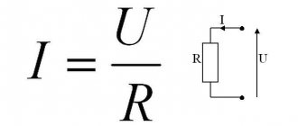
Ohm's law is the most important in electrical engineering. That is why electricians say: “Whoever does not know Ohm’s Law should sit at home.” According to this law, current is directly proportional to voltage and inversely proportional to resistance (I = U / R), where R is a coefficient that relates voltage and current.
The unit of measurement for voltage is Volt, resistance is Ohm, and current is Ampere.
To show how Ohm's Law works, let's look at a simple electrical circuit. The circuit is a resistor, which is also a load. A voltmeter is used to record the voltage across it. For load current - ammeter. When the switch is closed, current flows through the load. Let's see how well Ohm's Law is observed. The current in the circuit is equal to: circuit voltage 2 Volts and circuit resistance 2 Ohms (I = 2 V / 2 Ohms = 1 A). The ammeter shows this much. The resistor is a load with a resistance of 2 ohms. When we close switch S1, current flows through the load. Using an ammeter we measure the current in the circuit. Using a voltmeter, measure the voltage at the load terminals. The current in the circuit is equal to: 2 Volts / 2 Ohms = 1 A. As you can see, this is observed.
Now let's figure out what needs to be done to increase the current in the circuit. First, increase the voltage. Let's make the battery not 2 V, but 12 V. The voltmeter will show 12 V. What will the ammeter show? 12 V/ 2 Ohm = 6 A. That is, by increasing the voltage across the load by 6 times, we obtained an increase in current strength by 6 times.
Let's consider another way to increase the current in a circuit. You can reduce the resistance - instead of a 2 Ohm load, take 1 Ohm. What we get: 2 Volts / 1 Ohm = 2 A. That is, by reducing the load resistance by 2 times, we increased the current by 2 times. In order to easily remember the formula of Ohm's Law, they came up with the Ohm triangle: How can you determine the current from this triangle? I = U / R. Everything looks quite clear. Using a triangle, you can also write formulas derived from Ohm’s Law: R = U / I; U = I * R. The main thing to remember is that the voltage is at the vertex of the triangle.
In the 18th century, when the law was discovered, atomic physics was in its infancy. Therefore, Georg Ohm believed that the conductor is something similar to a pipe in which liquid flows. Only liquid in the form of electric current. At the same time, he discovered a pattern that the resistance of a conductor becomes greater as its length increases and less as its diameter increases.
Based on this, Georg Ohm derived the formula: R = p *l / S ,
where p is a certain coefficient multiplied by the length of the conductor and divided by the cross-sectional area. This coefficient was called resistivity, which characterizes the ability to create an obstacle to the flow of electric current, and depends on what material the conductor is made of. Moreover, the greater the resistivity, the greater the resistance of the conductor. To increase the resistance, it is necessary to increase the length of the conductor, or reduce its diameter, or select a material with a higher value of this parameter. Specifically, for copper the resistivity is 0.017 (Ohm*mm2/m).
Connecting resistance thermometers to an electrical measuring circuit
There are 3 schemes for connecting the sensor to the measuring circuit:
Connection diagram for a thermistor using a two-wire circuit.
2-wire.
The connection diagram for a simple resistance thermometer uses two wires. This scheme is used where high measurement accuracy is not required. The measurement accuracy is reduced due to the resistance of the connecting wires, which adds up to the thermometer’s own resistance and leads to an additional error. This scheme is not used for thermometers of classes A and AA.
3-wire.
This scheme provides significantly more accurate measurements due to the fact that it becomes possible to measure the resistance of the supply wires in a separate experiment and take into account their influence on the accuracy of measuring the resistance of the sensor.
We advise you to study POT RM 016 2001 (Occupational Safety and Health Rules)
4-wire.
It is the most accurate measurement scheme, ensuring complete exclusion of the influence of the supply wires on the measurement result. In this case, two conductors supply current to the thermistor, and the other two, in which the current is zero, are used to measure the voltage across it. The disadvantage of this solution is the increase in the volume of wires used, the cost and dimensions of the product. This circuit cannot be used in a four-arm Wheatstone bridge.
In industry, the most common is the three-wire circuit. For accurate and reference measurements, only a four-wire circuit is used.
Electrical resistance of the conductor
Electrical resistance is a physical quantity that shows what kind of obstacle is created by the current as it passes through a conductor. The units of measurement are Ohms, in honor of Georg Ohm. In his law, he derived a formula for finding resistance, which is given below.
Let's consider the resistance of conductors using metals as an example. Metals have an internal structure in the form of a crystal lattice. This lattice has a strict order, and its nodes are positively charged ions. Charge carriers in a metal are “free” electrons, which do not belong to a specific atom, but move randomly between lattice sites.
It is known from quantum physics that the movement of electrons in a metal is the propagation of an electromagnetic wave in a solid. That is, an electron in a conductor moves at the speed of light (practically), and it has been proven that it exhibits properties not only as a particle, but also as a wave. And the resistance of the metal arises as a result of the scattering of electromagnetic waves (that is, electrons) by thermal vibrations of the lattice and its defects. When electrons collide with nodes of a crystal lattice, part of the energy is transferred to the nodes, as a result of which energy is released. This energy can be calculated at constant current, thanks to the Joule-Lenz law - Q=I2Rt. As you can see, the greater the resistance, the more energy is released.
Resistivity
There is such an important concept as resistivity, this is the same resistance, only in a unit of length. Each metal has its own, for example, for copper it is 0.0175 Ohm*mm2/m, for aluminum it is 0.0271 Ohm*mm2/m. This means that a copper bar 1 m long and a cross-sectional area of 1 mm2 will have a resistance of 0.0175 Ohm, and the same bar, but made of aluminum, will have a resistance of 0.0271 Ohm. It turns out that the electrical conductivity of copper is higher than that of aluminum. Each metal has its own specific resistance, and the resistance of the entire conductor can be calculated using the formula
where p is the resistivity of the metal, l is the length of the conductor, s is the cross-sectional area.
Resistivity values are given in the table of metal resistivities (20°C)
| Substance | p, Ohm*mm2/2 | α,10-3 1/K |
| Aluminum | 0.0271 | 3.8 |
| Tungsten | 0.055 | 4.2 |
| Iron | 0.098 | 6 |
| Gold | 0.023 | 4 |
| Brass | 0.025-0.06 | 1 |
| Manganin | 0.42-0.48 | 0,002-0,05 |
| Copper | 0.0175 | 4.1 |
| Nickel | 0.1 | 2.7 |
| Constantan | 0.44-0.52 | 0.02 |
| Nichrome | 1.1 | 0.15 |
| Silver | 0.016 | 4 |
| Zinc | 0.059 | 2.7 |
In addition to resistivity, the table contains TCR values; more on this coefficient a little later.
Dependence of resistivity on deformation
During cold forming of metals, the metal experiences plastic deformation. During plastic deformation, the crystal lattice becomes distorted and the number of defects increases. With an increase in crystal lattice defects, the resistance to the flow of electrons through the conductor increases, therefore, the resistivity of the metal increases. For example, wire is made by drawing, which means that the metal undergoes plastic deformation, as a result of which the resistivity increases. In practice, recrystallization annealing is used to reduce resistance; this is a complex technological process, after which the crystal lattice seems to “straighten out” and the number of defects decreases, and therefore the resistance of the metal too.
When stretched or compressed, the metal experiences elastic deformation. During elastic deformation caused by stretching, the amplitudes of thermal vibrations of the crystal lattice nodes increase, therefore, electrons experience great difficulty, and in connection with this, the resistivity increases. During elastic deformation caused by compression, the amplitudes of thermal vibrations of the nodes decrease, therefore, it is easier for electrons to move, and the resistivity decreases.
Effect of temperature on resistivity
As we have already found out above, the cause of resistance in metal is the nodes of the crystal lattice and their vibrations. So, as the temperature increases, the thermal vibrations of the nodes increase, which means the resistivity also increases. There is such a value as the temperature coefficient of resistance (TCR), which shows how much the resistivity of a metal increases or decreases when heated or cooled. For example, the temperature coefficient of copper at 20 degrees Celsius is 4.1 · 10 − 3 1/degree. This means that when, for example, copper wire is heated by 1 degree Celsius, its resistivity will increase by 4.1 · 10 − 3 Ohms. The resistivity with temperature changes can be calculated using the formula
where r is the resistivity after heating, r0 is the resistivity before heating, a is the temperature coefficient of resistance, t2 is the temperature before heating, t1 is the temperature after heating.
Substituting our values, we get: r=0.0175*(1+0.0041*(154-20))=0.0271 Ohm*mm2/m. As you can see, our copper bar with a length of 1 m and a cross-sectional area of 1 mm2, after heating to 154 degrees, would have the same resistance as the same bar, only made of aluminum and at a temperature of 20 degrees Celsius.
The property of changing resistance with temperature changes is used in resistance thermometers. These devices can measure temperature based on resistance readings. Resistance thermometers have high measurement accuracy, but small temperature ranges.
In practice, the properties of conductors to prevent the passage of current are used very widely. An example is an incandescent lamp, where a tungsten filament is heated due to the high resistance of the metal, its large length and narrow cross-section. Or any heating device where the coil heats up due to high resistance. In electrical engineering, an element whose main property is resistance is called a resistor. A resistor is used in almost any electrical circuit.
Dependence of conductor resistance on temperature
Specific resistance, and therefore the resistance of metals, depends on temperature, increasing with temperature. The temperature dependence of conductor resistance is explained by the fact that
- the intensity of dispersion (number of collisions) of charge carriers increases with increasing temperature;
- their concentration changes when the conductor is heated.
Experience shows that at temperatures that are not too high and not too low, the dependences of resistivity and conductor resistance on temperature are expressed by the formulas:
\(~\rho_t = \rho_0 (1 + \alpha t) ,\) \(~R_t = R_0 (1 + \alpha t) ,\)
where ρ
0,
ρ
t are the specific resistances of the conductor substance at 0 °C and
t
°C, respectively;
R
0,
R
t - conductor resistance at 0 ° C and
t
° C,
α
- temperature coefficient of resistance: measured in SI in Kelvin minus the first power (K-1). For metal conductors, these formulas are applicable starting at temperatures of 140 K and above.
Temperature coefficient
The resistance of a substance characterizes the dependence of the change in resistance when heated on the type of substance.
It is numerically equal to the relative change in resistance (specific resistance) of the conductor when heated by 1 K. \(~\mathcal h \alpha \mathcal i = \frac{1 \cdot \Delta \rho}{\rho \Delta T} ,\)
where \(~\mathcal h \alpha \mathcal i\) is the average value of the temperature coefficient of resistance in the interval Δ T
.
For all metal conductors α
> 0 and varies slightly with temperature.
For pure metals α
= 1/273 K-1.
In metals, the concentration of free charge carriers (electrons) is n
= const and the increase in
ρ
occurs due to an increase in the intensity of scattering of free electrons on ions of the crystal lattice.
For electrolyte solutions α
< 0, for example, for a 10% solution of table salt
α
= -0.02 K-1. The resistance of electrolytes decreases with increasing temperature, since the increase in the number of free ions due to the dissociation of molecules exceeds the increase in the dispersion of ions during collisions with solvent molecules.
Formulas for dependence ρ
and
R
versus temperature for electrolytes are similar to the above formulas for metal conductors.
It should be noted that this linear dependence is preserved only in a small temperature range, in which α
= const. At large temperature ranges, the dependence of the electrolyte resistance on temperature becomes nonlinear.
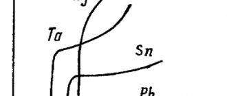
Graphically, the dependences of the resistance of metal conductors and electrolytes on temperature are shown in Figures 1, a, b.
Rice. 1
At very low temperatures, close to absolute zero (-273 °C), the resistance of many metals abruptly drops to zero. This phenomenon is called superconductivity
. The metal goes into a superconducting state.
The dependence of metal resistance on temperature is used in resistance thermometers. Usually, platinum wire is used as the thermometric body of such a thermometer, the dependence of whose resistance on temperature has been sufficiently studied.
Temperature changes are judged by changes in wire resistance, which can be measured. Such thermometers allow you to measure very low and very high temperatures when conventional liquid thermometers are unsuitable.
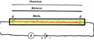
Metals
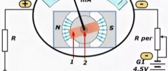
How does temperature affect metals? To find out this relationship, the following experiment was carried out: a battery, an ammeter, a wire and a burner are connected to each other using wires. Then you need to measure the current in the circuit. After the readings have been taken, you need to bring the burner to the wire and heat it. When the wire is heated, it can be seen that the resistance increases and the conductivity of the metal decreases.
Where:
- Metal wire
- Battery
- Ammeter
You also need to pay attention to such a property as superconductivity. If environmental conditions are normal, then as the conductors cool, they reduce their resistance. The graph below shows how temperature and resistivity vary in mercury.
Superconductivity is a phenomenon that occurs when a material reaches a critical temperature (closer to zero Kelvin) at which the resistance suddenly decreases to zero.
What is the difference between a thermoresistance and a thermocouple?
The principle of operation of the vehicle is explained by a change in the conductivity of the control section of the circuit. The thermocouple, despite having a similar name, functions differently. Products in this category are made from two different materials. The connection (working solder) is placed in the measurement area. Temperature fluctuations provoke changes in potentials at the outputs. These readings are recorded with a voltmeter or other suitable device.
Thermocouple operating principle, functional components and measurement methods
For your information. The information provided explains the main practical differences between different types of sensors. The thermocouple is actually an EMF generator, so an additional current source is not needed.
A thermocouple transducer can be used to measure vacuum. To do this, ensure contact of the sensitive area with the filament of the incandescent lamp. The flask is connected by a tube to the working area. A change in gas rarefaction is accompanied by an increase (decrease) in EMF. After calibrating the scale, you can determine the value of the controlled parameter quite accurately.
How does temperature affect metals? To find out this relationship, the following experiment was carried out: a battery, an ammeter, a wire and a burner are connected to each other using wires. Then you need to measure the current in the circuit. After the readings have been taken, you need to bring the burner to the wire and heat it. When the wire is heated, it can be seen that the resistance increases and the conductivity of the metal decreases.
Where:
- Metal wire
- Battery
- Ammeter
The dependence is indicated and justified by the formulas:
From these formulas it follows that R of the conductor is determined by the formula:
An example of the dependence of metal resistance on temperature is provided in the video:
You also need to pay attention to such a property as superconductivity. If the environmental conditions are normal, then as the conductors cool, they reduce their resistance
The graph below shows how temperature and resistivity vary in mercury.
Superconductivity is a phenomenon that occurs when a material reaches a critical temperature (closer to zero Kelvin) at which the resistance suddenly decreases to zero.
The role of the current conductor
If a source of EMF is connected to a substance or material with conductive ability, then an electric current begins to flow through it. Free electrons of the substance begin a directed movement from the negative pole to the positive one, since they are carriers of a negative charge.
During directed motion, electrons strike atoms of the material and transfer some of their energy to them, which causes heating of the conductor through which the current passes. And after a collision, electrons slow down their movement. But the electric field accelerates them again, so they continue their directed movement towards the plus.
This process can go on almost endlessly as long as there is an electric field around the conductor created by a source of electromotive force. It turns out that the more obstacles there are in the path of electrons, the higher the resistance value.
Different substances have different numbers of free electrons, and the atoms between which free charge carriers move have different locations. Therefore, resist. current conductors depends, first of all, on the material from which they are made, on the area and length of the cross section.
If we compare two conductors made of the same material, then the longer one has a larger R with equal cross-sectional areas, and the one with a larger cross-section has a lower resistance. at equal lengths. Let's consider a practical example: Let's connect a 60W incandescent light bulb to an outlet with mains voltage. The spiral of the light bulb begins to create some obstacle to the flow of electrons with a potential of 220V.
If this barrier to the electrons is too small, the light bulb will burn out. If it is too large, the filament will burn very weakly. But if it is “optimal”, then the light bulb will burn normally, releasing heat at the same time. The heat generated is called “lost” energy, since some of the energy is lost to unnecessary heat.
What is electrical resistivity? From the formula of Ohm's law we can write that electrical resistance is a physical quantity that can be calculated as the ratio of the voltage in a conductor to the strength of the current flowing in it.
So, based on the experiment with the light bulb just above, we can conclude that the electrical resistance of a conductor is a physical quantity that indicates the property of a substance to convert electrical energy into thermal energy.
(R= ρ × l)/S
ρ is the resistivity of the conductor material, Ohm m, l is the length, m, and S is the cross-sectional area, m2. Electrical resistivity is also a physical quantity that is equal to the resistance of a meter-long conductor with a cross-sectional area of one square meter. In practice, the cross-section is measured in square millimeters.
Resistance of various metals
Therefore, it is easier to calculate the specific electrical resistance in Ohm × mm2 / m, and substitute the area in mm2. The formula above says that the specific resistivity. directly proportional to specific resistance. the material from which it is made, as well as its length and is inversely proportional to the cross-sectional area of the conductor.
Resistance conductors also depends on temperature. So, for metal elements, R increases with increasing temperature. This dependence is complex, but within a relatively narrow range of temperature changes (up to approximately 200° Celsius), we can conditionally assume that for each metal there is a certain, so-called temperature, resistance coefficient (alpha), which expresses a certain increase in resistance delta r when the temperature changes by one degree Celsius per 1 ohm of the initial resistance value. Thus, the temperature coefficient of resistivity will be equal to α = r2-r1/r1(T2-T1) and the increase in resistivity. will be equal to Δr=r2-r1=αr2(T2-T1)
For example, for a copper linear wire at a temperature T1 = 15° r1 = 50 ohms, and at a temperature T2 = 75° - r2 - 62 ohms. Therefore, the delta when the temperature changes by 75 - 15 = 60° will be equal to 62 - 50 = 12 ohms. That is, the delta corresponding to a temperature change of 1° is equal to: 12/60 = 0.2 What does the resistivity depend on.
Firstly, from the conductor material. The larger the value of ρ, the worse the current carrying capacity will be. Secondly, it depends on the length of the wire - as the length increases, the resistance increases. Thirdly, on thickness. A thicker conductor has lower resistance. And fourthly, on the temperature of the conductor.
If it is made of metal, then their resistivity increases with increasing temperature. An exception can be made to special alloys – their electrical resistivity. practically does not change when heated. For example: nickel, constantan and manganin. But when liquids are heated, the resistivity decreases.
The connection with specific conductivity in isotropic materials is expressed by the formula: ρ = 1 / σ Where σ is specific conductivity. The phenomenon of superconductivity Suppose we decrease the temperature of the material, then the resistivity will also decrease. There is a limit to which the temperature can be reduced - absolute zero.
Conductor in section
In numerical terms, it is equal to -273°C. Temperatures below this value simply do not exist. At this value, the resistivity of any conductor will be zero. since at absolute zero the atoms of the crystal lattice completely stop vibrating. As a result, the electron cloud passes between lattice nodes without colliding with them. Specific resistance material becomes equal to zero, which opens up the possibility of obtaining infinitely large current levels in conductors of small cross-section. The phenomenon of superconductivity opens up fantastic prospects for the development of electrical and electronic engineering. But there are still some difficulties associated with obtaining in everyday life the ultra-low temperature values required to create the desired effect. When these problems can be overcome, electrical engineering will step to a fundamentally new level of development.
Gases
Gases act as dielectrics and cannot conduct electric current. And in order for it to form, charge carriers are needed. Their role is played by ions, and they arise due to the influence of external factors.
The dependency can be illustrated with an example. For the experiment, the same design is used as in the previous experiment, only the conductors are replaced with metal plates. There should be a small space between them. The ammeter should indicate no current. When placing a torch between the plates, the device will indicate the current that passes through the gaseous medium.
Below is a graph of the current-voltage characteristics of a gas discharge, which shows that the growth of ionization at the initial stage increases, then the dependence of the current on the voltage remains unchanged (that is, as the voltage increases, the current remains the same) and a sharp increase in the current strength, which leads to breakdown of the dielectric layer .
Let's consider the conductivity of gases in practice. The passage of electric current in gases is used in fluorescent lamps and lamps. In this case, the cathode and anode, two electrodes are placed in a flask, inside of which there is an inert gas. How does this phenomenon depend on gas? When the lamp is turned on, the two filaments heat up and thermionic emission is created. The inside of the bulb is coated with a phosphor, which emits the light that we see. How does mercury depend on the phosphor? Mercury vapor, when bombarded with electrons, produces infrared radiation, which in turn emits light.
If a voltage is applied between the cathode and anode, gas conduction occurs.
Laws of physics and current in liquids
Electricity in our homes and equipment, as a rule, is not transmitted in metal wires. In a metal, electrons can move from atom to atom, and thus carry a negative charge.
As liquids, they are carried in the form of electrical voltage, known as voltage, in units of volts, named after the Italian scientist Alessandro Volta.
Video: Electric current in liquids: complete theory
Also, electric current flows from high voltage to low voltage and is measured in units known as amperes, named after Andre-Marie Ampere. And according to the theory and formula, if you increase the voltage, then its strength will also increase proportionally. This relationship is known as Ohm's law. As an example, the virtual ampere characteristic is below.
Figure: current versus voltage
Ohm's Law (with additional details regarding the length and thickness of the wire) is typically one of the first things taught in physics classes, many students and teachers therefore treat electric current in gases and liquids as a fundamental law in physics.
High alloy steels
High-alloy steels have electrical resistivity several times higher than carbon and low-alloy steels. According to the table, it can be seen that at a temperature of 20°C its value is (30...86)·10-8 Ohm·m.
At a temperature of 1300°C, the resistance of high- and low-alloy steels becomes almost the same and does not exceed 131·10-8 Ohm·m.
Electrical resistivity of high-alloy steels ρе·108, Ohm·m
| steel grade | 20 | 100 | 300 | 500 | 700 | 900 | 1100 | 1300 |
| G13 | 68,3 | 75,6 | 93,1 | 95,2 | 114,7 | 123,8 | 127 | 130,8 |
| G20H12F | 72,3 | 79,2 | 91,2 | 101,5 | 109,2 | — | — | — |
| G21X15T | — | 82,4 | 95,6 | 104,5 | 112 | 119,2 | — | — |
| Х13Н13К10 | — | 90 | 100,8 | 109,6 | 115,4 | 119,6 | — | — |
| Х19Н10К47 | — | 90,5 | 98,6 | 105,2 | 110,8 | — | — | — |
| P18 | 41,9 | 47,2 | 62,7 | 81,5 | 103,7 | 117,3 | 123,6 | 128,1 |
| EH12 | 31 | 36 | 53 | 75 | 97 | 119 | — | — |
| 40Х10С2М (EI107) | 86 | 91 | 101 | 112 | 122 | — | — | — |
Liquids
Current conductors in a liquid are anions and cations that move due to an external electric field. Electrons provide little conductivity. Let's consider the dependence of resistance on temperature in liquids.
Where:
- Electrolyte
- Battery
- Ammeter
The dependence of the effect of electrolytes on heating is prescribed by the formula:
Where a is the negative temperature coefficient.
How R depends on heating (t) is shown in the graph below:
This dependence must be taken into account when charging batteries and batteries.
Exercise
An overhead three-wire line of length L is made of wire, the brand of which is given in Table 2.1. It is necessary to find the value indicated by the sign “?”, using the given example and selecting the option with the data specified in it from Table 2.1.
It should be noted that the problem, unlike the example, involves calculations related to one line wire. In brands of bare wires, the letter indicates the material of the wire (A - aluminum; M - copper), and the number indicates the cross-section of the wire in mm
| Line length L, km | Wire brand | Wire temperature T, °C | Wire resistance RT at temperature T, Ohm |
The study of the topic material ends with work with tests No. 2 (TOE-
ETM/PM” and No. 3 (TOE – ETM/IM)
The kinetic energy of atoms and ions increases, they begin to oscillate more strongly around equilibrium positions, and electrons do not have enough space for free movement.
How does the resistivity of a conductor depend on its temperature? In what units is the temperature coefficient of resistance measured?
The resistivity of conductors increases linearly with increasing temperature according to the law.
How can we explain the linear dependence of the resistivity of a conductor on temperature?
The resistivity of a conductor depends linearly on the frequency of collisions of electrons with atoms and ions of the crystal lattice, and this frequency depends on temperature.
Why does the resistivity of semiconductors decrease with increasing temperature?
As the temperature increases, the number of free electrons increases, and as the number of charge carriers increases, the resistance of the semiconductor decreases.
Dependence of resistance on temperature
“All this is not because I’m so smart.
This is all because I took so long
I don’t give up when solving problems”
Albert Einstein
This topic is devoted to solving problems on the dependence of conductor resistance on temperature
Task 1.
Find the resistance of an aluminum wire with a length of 20 m and a cross-sectional area of 2 mm2 at a temperature of 70 ºC, taking into account that the table shows resistivity values at a temperature of 20 ºC.
| GIVEN: | SOLUTION The dependence of resistivity on temperature has the form Then at a temperature of 70 ºС The conductor resistance can be determined by the formula Then at a temperature of 70 ºС |
Answer
: 0.32 Ohm.
Task 2.
The incandescent lamp cylinder says 220 V, 100 W. When the filament was cold, i.e. room temperature, a voltage of 2 V was applied to it and the current was measured. The current turned out to be 50 mA. Find the approximate temperature of the filament, given that it is made of tungsten.
| GIVEN: | SI | SOLUTION From the formula for determining the power of electric current, we determine the resistance Let's write Ohm's law for a section of the circuit Then Let us write down the dependence of resistance on temperature Let us write down the expression for resistance at a certain temperature t 1 Then the resistance ratio t from this formula Resistance values at temperatures t and Then |
Answer:
The approximate filament temperature is 2462 ºС.
Task 3.
The copper wire is heated by electric current from 0 to 25 ºС in 3 minutes. A current of 50 A flows through the wire. Assuming that the change in current is negligible, find the work done by the current when the wire is heated. The wire resistance at 0 ºС is 200 mOhm.
| GIVEN: | SI | SOLUTION The work done by electric current is calculated by the formula Electric current power Initial resistance is resistance at zero degrees To calculate resistance at 25 ºС, it is necessary to record the dependence of resistance on temperature Let's calculate the current power at 0 and 25 ºС As can be seen from the formula, power depends linearly on resistance, and resistance, in turn, linearly depends on temperature. Therefore, power will depend linearly on temperature. To find the work of current, it is necessary to plot a graph of power versus time. To find the work done by the current, you need to find the area under the graph. The area of the trapezoid is Then work |
Answer
: 94.5 kJ.
Task 4.
Some voltage is applied to the ends of the wire. As the wire was heated to 50 ºС, the current decreased from 1 to 0.9 A. Find the initial temperature of the wire if its temperature coefficient of resistance is 0.004 ºС–1.
| GIVEN: | SOLUTION Let's write Ohm's law for a section of the circuit Based on this law, we write down the resistance of the wire at the initial and final temperatures The ratio of these resistances is Dependence of resistance on temperature Then for the initial and final temperatures the resistance is equal to The relationship of these resistances Let us equate two formulas expressing the resistance ratios From the last formula we express the initial temperature |
Answer:
20 ºС
Task 5.
Two identical wires are connected in parallel. One of these wires is placed in melting ice, and the other is at a temperature of 20 ºС. The temperature coefficient of resistance of the wires is 0.01 ºС–1. Compare the total resistance of this section with the resistance that would be if both wires were at a temperature of 20 ºC.
| GIVEN: | SOLUTION The dependence of resistance on temperature has the form Then at temperatures 0 ºС and 20 ºС In parallel connection If two identical wires are at the same temperature, then their resistances are equal In parallel connection Then the resistance ratio is |
Answer:
if two wires were at a temperature of 20 ºС, then the resistance of this section would be 1.1 times greater.