- home
- Directory
- Laws
- Ampere's law
- Ampere's law
- The meaning of Ampere's law
Ampere's law shows the force with which a magnetic field acts on a conductor placed in it. This force is also called the Ampere force.
Ampere was the first to establish that conductors through which electric current flows interact mechanically (attract or repel).
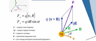
The force acting on a current-carrying conductor in a magnetic field is called the Ampere force. Its designations are: \( \overrightarrow{F} \),\( \overrightarrow{F}_{A} \). The force (\( \overrightarrow{F} \)), which acts on a straight conductor with current (I), is always perpendicular to the conductor and the direction of the magnetic induction vector (\( \overrightarrow{B} \)). If a straight conductor is located parallel to the direction of the magnetic field lines, the field does not act.
The specific direction of the Ampere force can be found using the left-hand rule. The left hand must be positioned so that the field lines enter the palm, the four fingers are directed along the current, then the thumb bent 90 degrees will indicate the direction of the Ampere force.
Ampere also established that two parallel conductors with current attract if the currents have the same directions and repel if the currents flow in opposite directions. This is easy to explain if you imagine that one conductor creates a magnetic field, and another conductor is placed in it and this field acts on it. You can use the left hand rule and figure out which way the force is directed.
Ampere's law
Ampere force is a force acting on a current conductor located in a magnetic field and equal to the product of the current strength in the conductor, the magnitude of the magnetic field induction vector, the length of the conductor and the sine of the angle between the magnetic field vector and the direction of the current in the conductor.
For a straight conductor the Ampere force
has the form:
\[ \large{\overrightarrow{F}_{A}} = I \cdot \overrightarrow{B} \cdot \overrightarrow{l} \cdot sin(α) \]
where: \( I \) is the current strength that flows in the conductor, \( \overrightarrow{B} \) is the induction vector of the magnetic field in which the conductor is placed, \( \overrightarrow{l} \) is the length of the conductor in the field , the direction is given by the direction of the current, \( \alpha \) is the angle between the vectors \( \overrightarrow{l\ }and\ \overrightarrow{B} \).
This formula can be used:
- if the length of the conductor is such that the induction at all points of the conductor can be considered the same;
- if the magnetic field is uniform (then the length of the conductor can be any, but the entire conductor must be in the field).
If the size of the conductor is arbitrary and the field is non-uniform, then the formula is as follows:
\[ \large{d\overrightarrow{F}_{A}} = I \cdot \overrightarrow{B} \cdot d\overrightarrow{l} \cdot sin(α) \]
Magnetic force
The force acting on a current-carrying conductor from the magnetic field was named after the discoverer - the Ampere force. Experiments have shown that the ampere force modulus F is proportional to the length of the conductor L and depends on the spatial position of the conductor in the magnetic field.
To quantitatively describe the effect of a magnetic field on a current-carrying conductor, a quantity called magnetic induction B was introduced. Then the Ampere force will be equal to:
$F = B*I*L$ (1),
where I is the current strength. This formula is valid when calculating the modulus of the maximum value of the Ampere force acting on a straight conductor in a magnetic field; the magnetic field vector B is directed at 900 to the current vector I.
If the conductor is located at an angle α to the magnetic induction vector B, then instead of formula (1) the following formula should be used:
$F = B*I*L*sinα$ (2).
The meaning of Ampere's law
Based on Ampere's law, current units are established in the SI and SGSM systems. Since an ampere is equal to the strength of a direct current, which, when flowing through two parallel infinitely long straight conductors of an infinitely small circular cross-section, located at a distance of 1 m from each other in a vacuum, causes an interaction force of these conductors equal to \( 2\cdot {10}^{-7 }N\) for each meter of length.
A current of one ampere is a current at which two homogeneous parallel conductors located in a vacuum at a distance of one meter from each other interact with a force of \( 2\cdot {10}^{-7} \) Newton.
The law of interaction of currents - two parallel conductors located in a vacuum, the diameters of which are much smaller than the distances between them, interact with a force directly proportional to the product of the currents in these conductors and inversely proportional to the distance between them.
Laws Formulas Physics Theory Electricity Law
Source
Ampere's law. Interaction of parallel currents
The magnetic field has an orienting effect on the current-carrying frame. Consequently, the torque experienced by the frame is the result of the action of forces on its individual elements. Summarizing the results of a study of the effect of a magnetic field on various current-carrying conductors, Ampere established that the force d F with which the magnetic field acts on a conductor element d l
with current in a magnetic field is directly proportional to the current strength
I
in the conductor and the vector product of the element of length
no d l of the conductor for magnetic induction B:
d F = I
[d
l , B ].
(111.1) The direction of the vector d F can be found, according to (111.1), according to the general rules of the vector product, from which the rule of the left hand follows: if the palm of the left hand is positioned so that vector B enters it, and the four outstretched fingers are positioned in the direction of the current in a conductor, then the bent thumb will show the direction of the force acting on the current.
Ampere force modulus (see (111.1)) is calculated by the formula
dF = IB
d
l
sina, (111.2)
where a is the angle between vectors dl and B.
Ampere's law is used to determine the strength of interaction between two currents. Consider two infinite rectilinear parallel currents I
1 and
I
2 (the directions of the currents are indicated in Fig. 167), the distance between which is equal to
R.
Each of the conductors creates a magnetic field that acts according to Ampere’s law on the other conductor with current.
Let's consider the force with which the magnetic field of current I
1 acts on element d
l
of the second conductor with current I
2.
Current I
1
creates a magnetic field around itself, the lines of magnetic induction of which are concentric circles.
The direction of the vector b 1 is given by the rule of the right screw, its module according to formula (110.5) is equal to
Direction of force d F 1 with which field B 1 acts on section d l
the second current is determined by the left-hand rule and is indicated in the figure.
The magnitude of the force, according to (111.2), taking into account the fact that the angle a between the elements of the current I
2 and the straight vector
B 1 is equal to
d F
1=
I
2
B
1d
l
, or, substituting the value for
B
1
,
we get
Reasoning similarly, we can show that the force d F 2 with which the magnetic field of the current I
2 acts on element d
l
of the first conductor with current
I
1
,
is directed in the opposite direction and is equal in magnitude
Comparison of expressions (111.3) and (111.4) shows that
dF1=dF2,
i.e. two parallel currents of the same direction are attracted to each other
with force
If the currents are in opposite directions,
then, using the left-hand rule, we can show that there is
a repulsive force between them,
determined by formula (111.5).
EXAMPLES OF TASKS
Part 1
1. The figure shows how the magnetic needle is established between the poles of two identical magnets. Indicate the poles of the magnets facing the arrow.
1) 1 - S, 2 - N 2) 1 - A, 2 - N 3) 1 - S, 2 - S 4) 1 - N, 2 - S
2. The figure shows a picture of the magnetic field lines from two strip magnets, obtained using a magnetic needle and iron filings. Which poles of the strip magnets correspond to areas 1 and 2?
1) 1 - north pole; 2 - southern 2) 1 - southern; 2 - to the north pole 3) and 1, and 2 - to the north pole 4) and 1, and 2 - to the south pole
3. When an electric current passes through a conductor, the magnetic needle located nearby is located perpendicular to the conductor. When the direction of current is reversed. Arrow
1) will rotate by 90° 2) will rotate by 180° 3) will rotate by 90° or 180° depending on the current value 4) will not change its position
4. The conductor through which electric current flows is located perpendicular to the plane of the drawing (see figure). The location of which of the magnetic needles interacting with the magnetic field of a current-carrying conductor is shown correctly?
5. A ring was made from a conductor and an electric current was passed through it. The current is directed counterclockwise (see figure). What is the direction of the magnetic induction vector in the center of the ring?
1) to the right 2) to the left 3) towards us from behind the drawing plane 4) away from us beyond the drawing plane
6. An electric current flows through the coil, the direction of which is shown in the figure. At the same time, at the ends of the iron core of the coil
1) magnetic poles are formed - at end 1 - the north pole, at end 2 - the south 2) magnetic poles are formed - at end 1 - the south pole, at end 2 - the north 3) electrical charges accumulate: at end 1 - a negative charge, on end 2 - positive 4) electrical charges accumulate: at end 1 - positive charge, at end 2 - negative
7. Two parallel conductors are connected in parallel to a current source.
The direction of electric current and the interaction of conductors are correctly depicted in the figure.
8. In a uniform magnetic field, a current-carrying conductor located perpendicular to the plane of the drawing (see figure) is acted upon by a force directed
1) right → 2) left ← 3) 4) down ↓
9. The force acting on a conductor with current, which is in a magnetic field between the poles of a magnet, is directed
1) 2) down ↓ 3) right → 4) left ←
10. The figure shows a current-carrying conductor placed in a magnetic field. The arrow indicates the direction of current in the conductor. The magnetic induction vector is directed perpendicular to the plane of the drawing towards us. What is the direction of the force acting on a current-carrying conductor?
1) 2) right → 3) down ↓ 4) left ←
11. From the statements below, choose two correct ones and write their numbers in the table.
1) There is a magnetic field around stationary charges. 2) There is an electrostatic field around stationary charges. 3) If you cut a magnet into two parts, then one part will have only the north pole, and the other will have only the south pole. 4) A magnetic field exists around moving charges. 5) A magnetic needle located near a current-carrying conductor always rotates around its axis.
12. The electrical circuit contains a current source, conductor AB, a switch and a rheostat. The conductor AB is placed between the poles of a permanent magnet (see figure).
Using the picture, select two true statements from the list provided. Indicate their numbers.
1) When you move the rheostat slider to the left, the Ampere force acting on conductor AB will increase. 2) When the key is closed, the conductor will be pushed out of the magnet area to the right. 3) When the key is closed, the electric current in the conductor is directed from point B to point A. 4) The magnetic field lines of the permanent magnet in the area where the conductor AB is located are directed vertically downward. 5) Electric current flowing in conductor AB creates a uniform magnetic field.
Part 2
13. A section of conductor 0.1 m long is in a magnetic field with an induction of 50 mT. The current flowing through the conductor is 10 A. How much work is done by the ampere force when the conductor moves 8 cm in the direction of its action? The conductor is located perpendicular to the lines of magnetic induction.
Source
Ampere power
Ampere's experiments, as we have seen (see Interaction of conductors with currents), showed that two conductors attract or repel depending on the direction of the current in them.
This interaction is explained by the fact that the force experienced by each of the conductors is due to the magnetic field created by the current of the other conductor. In general, a magnetic field acts with some force on any current-carrying conductor located in this field.
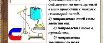
Indeed, let us arrange the current-carrying conductor (see Fig. 1) so that only one straight section of it ab
found itself in a strong magnetic field (between the poles of a horseshoe magnet), and the remaining parts of the circuit were in areas of space where the magnetic field is weak and its effect on these parts of the circuit can be neglected.
Experience shows that, depending on the direction of the current and the location of the magnet poles, the conductor ab
moves right or left, up or down.
Forces do not act on conductors located along the direction of the magnetic field. Rice.
1 The force acting on a current-carrying conductor in a magnetic field is called the Ampere force
.
The direction of the Ampere force can be determined using the left hand rule
:
the hand is positioned so that the component of magnetic induction normal to the conductor enters the palm, four extended fingers are directed along the current: then the thumb bent 90° will indicate the direction of the Ampere force acting on the conductor
(Fig. . 1).
Ampere established experimentally that the magnitude of this force is greater, the stronger the magnetic field \(~(F_A \sim B)\), the greater the current strength \(~(F_A \sim I)\) in the conductor, the greater the length of the conductor \ (~(F_A \sim l)\) and depends on the orientation of the conductor in the magnetic field:
\(~F_A = BI\Delta l \sin \alpha\)
where α is the angle between the direction of the current in the conductor and the magnetic induction vector.
This formula is a mathematical expression of Ampere's law
. It can be used only when the length of the conductor is such that the induction at all points of the conductor can be considered the same, but if the magnetic field is uniform, then the length of the conductor can be any, but the entire conductor must be in the field. Of interest is the rotation of a rectangular frame with current in a uniform magnetic field.
The forces acting on a current-carrying conductor in a magnetic field are widely used in technology. Electric motors and generators, devices for recording sound in tape recorders, telephones and microphones - all of these and many other devices and devices use the interaction of currents, currents and magnets, etc.
6.5. Interaction of two conductors with current
Let's apply Ampere's law to calculate the force of interaction between two long straight conductors with currents I1 and I2, located at a distance d from each other (Fig. 6.26).
Rice. 6.26. Power interaction of rectilinear currents: 1 - parallel currents; 2 - antiparallel currents
Video 6.2. Interaction of two parallel conductors with current.
A conductor with current I1 creates an annular magnetic field, the magnitude of which at the location of the second conductor is equal to
| (6.23) |
This field is directed “away from us” orthogonally to the plane of the drawing. The element of the second conductor experiences the action of the Ampere force from the side of this field
| (6.24) |
Substituting (6.23) into (6.24), we get
| (6.25) |
With parallel currents, force F21 is directed towards the first conductor (attraction), with antiparallel currents - in the opposite direction (repulsion).
Similarly, element 1 of conductor is affected by a magnetic field created by a conductor with current I2 at a point in space with an element with force F12. Reasoning in the same way, we find that F12 = –F21, that is, in this case Newton’s third law is satisfied.
So, the force of interaction between two straight infinitely long parallel conductors, calculated per element of the length of the conductor, is proportional to the product of the current forces I1 and I2 flowing in these conductors, and inversely proportional to the distance between them. In electrostatics, two long charged threads interact according to a similar law.
In Fig. Figure 6.27 presents an experiment demonstrating the attraction of parallel currents and the repulsion of antiparallel ones. For this purpose, two aluminum strips are used, suspended vertically next to each other in a slightly tensioned state. When parallel direct currents of about 10 A are passed through them, the ribbons are attracted. and when the direction of one of the currents changes to the opposite, they repel.
Rice. 6.27. Force interaction of long straight conductors with current
Based on formula (6.25), the unit of current is established - ampere, which is one of the basic units in SI.
| An ampere is the strength of a constant current, which, flowing through two long parallel conductors located in a vacuum at a distance of 1 m, causes an interaction force between them of 2 × 10⁻⁷ N for each meter of wire length. |
Example. Two thin wires, bent in the form of identical rings with a radius R = 10 cm, carry identical currents I = 10 A in each. The planes of the rings are parallel, and the centers lie on a line orthogonal to them. The distance between centers is d = 1 mm. Find the forces of interaction between the rings.
Solution. In this problem it should not be confusing that we only know the law of interaction of long straight conductors. Since the distance between the rings is much less than their radius, the interacting elements of the rings “do not notice” their curvature. Therefore, the interaction force is given by expression (6.25), where we must substitute the circumference of the rings. We then obtain
online.mephi.ru
The force of interaction of two parallel conductors with currents
If we take two parallel conductors with currents located at a distance a from each other, then their own magnetic field will arise around each of them, and the conductor with current I1 will be in the magnetic field of the conductor with current I2 and vice versa. As a result, electromagnetic forces F1 and F2 will act on the conductors, the direction of which is determined by the left-hand rule.
Þ wires with currents of the same direction are attracted to each other with a force F.
Magnetization of ferromagnetic materials
In ferromagnets. They are used in all electrical machines. If you introduce a ferromagnetic core into a coil with current, the magnetic field of this coil increases by hundreds and thousands of times.
Ferromagnets contain randomly magnetized regions called domains , or regions of spontaneous magnetization. Their magnetic fields are directed chaotically, and the resulting magnetic field is equal to “0”.
If such a ferromagnet is placed in an external magnetic field, for example, in a coil with current, then the domains will turn in the direction of the external magnetic field, and the resulting field increases sharply. In this case, they say that the ferromagnet has become magnetized.
The process of magnetization of a ferromagnet placed in a coil with current can be explained using a magnetization curve.
— Stoletov curve
Under the influence of an external field created by the current in the coil, the domains will begin to orient themselves in the direction of the external field.
The curve can be divided into three sections:
1. Section OA - here the magnetic induction increases in proportion to the increase in magnetic field strength;
2. Section AB (curve knee) – here the growth of magnetic induction slows down, because most domains are already oriented in the direction of the external field; the proportionality between B and H is violated;
3. Section BC - here all domains are oriented in the direction of the external field, the growth of magnetic induction stops. Magnetic saturation occurs.
Magnetization reversal of ferromagnets
Magnetic hysteresis
| If, after reaching core saturation, the current in the coil (external field strength) is reduced, then the magnetic induction will also decrease, because some of the domains will return to the position they occupied before magnetization. However, the other part will remain oriented in the direction of the external magnetic field. |
At point A, the external magnetic field is zero, but the magnetic induction is not zero. This value of magnetic induction is called remanent magnetic induction .
To demagnetize the core, it is necessary to apply an external field in the opposite direction and bring it to a value determined by the OF segment, which is called the coercive force. If we continue to increase the external field, we will again obtain saturation.
Conclusions:
1. The change in magnetic induction lags (lags) in time from the change in the external field strength.
2. This delay is called magnetic hysteresis, and the magnetization curve characterizing this process is called a hysteresis loop.
3. Magnetization reversal of ferromagnets is associated with the expenditure of energy, which is converted into heat. The energy losses associated with the magnetization reversal process are called hysteresis losses.
The amount of energy spent on 1 magnetization reversal cycle is proportional to the area of the hysteresis loop.
When magnetization reversal occurs, the size of the bodies changes (10-6). This phenomenon is called magnetostriction.
Magnetically hard and soft magnetic materials
Magnetic soft - well magnetized and well demagnetized. Their hysteresis loop area is small. The coercive force is small. They have high magnetic permeability.
| These include electrical steel, transformer steel, permolon (iron with nickel). They are used in all electromagnets. |
Magnetically hard - they are poorly magnetized and demagnetized poorly. They are characterized by a large area of the hysteresis loop, large coercive force and residual magnetic induction.
These include carbon, tungsten, cobalt and other alloys.
Magnetic circuits
A magnetic circuit is a device in which a magnetic flux is closed. There are branched and unbranched.
| Straight chain | Branched chain |
In addition, magnetic circuits can be homogeneous or inhomogeneous. Homogeneous chains are made from the same material and have the same cross-sectional area.
Ohm's law and Kirchhoff's law for magnetic circuits
Ohm's law : magnetic voltage in any area because .
If , then , where is the magnetic resistance. .
Magnetic flux is directly proportional to magnetic voltage and inversely proportional to magnetic resistance.
Kirchhoff's law
Rule 1: the algebraic sum of the magnetic currents at the branch point is 0.
Rule 2: based on the law of total current.
The algebraic sum of the MMF is equal to the algebraic sum of the magnetic stresses in individual sections of the circuit.
.
Ohm's law and Kirchhoff's law are not used to calculate magnetic circuits, because Magnetic resistance, unlike electrical resistance, depends on the magnitude of the magnetic voltage.
To calculate magnetic circuits, the law of total current is used.