What does Ohm's law sound like for a section of a circuit?
If we talk about the official formulation, then Ohm’s law can be stated as follows:
Current strength has a direct relationship with voltage and an inverse relationship with resistance. This statement is true for a section of a circuit with some specific and stable resistance.
The formula for this dependence is in the figure. Here I is the current, U is the voltage, R is the resistance.
Ohm's law formula
- The higher the voltage, the higher the current.
- The greater the resistance, the less current.
It is not so easy to imagine the meaning of this expression. After all, electricity cannot be seen. We only know approximately what it is. Let's try to understand the meaning of this law with the help of analogies.
Confirmation of Ohm's law
The boom in the study of electrical phenomena occurred at the end of the 18th and beginning of the 19th centuries. Scientists such as Faraday, Ampere, Volt, Oersted, Coulomb, Lachinov, Ohm conducted a number of experiments that allowed Maxwell to create a theory of electromagnetic phenomena.
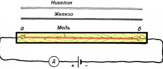
A huge role in the discovery of new knowledge was played by Ohm's experience in researching what the current strength in a circuit depends on . The German physicist conducted experiments on the conductivity of various materials. To do this, he used an electrical circuit, into the gap of which he connected conductors of different lengths and measured the current strength.
Initially, the scientist was unable to establish a pattern. The thing is that Om used a chemical battery for his experiments. The scientist's friend Poggendorff suggested using a thermoelectric current source. As a result, the physicist was able to trace the dependence. He described it as follows: the quotient of a divided by l + b, where b determines the intensity of the impact on a conductor of length l, and a and b are constants, depending respectively on the acting force and resistance of the circuit elements.
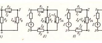
Usually, when studying the law in the seventh grade of high school, the teacher demonstrates this dependence in practical lessons. To do this, so that students can verify the validity of the statement, the teacher assembles an electrical circuit, which includes:
- voltmeter - a device for measuring voltage, connected in parallel to the conductor being measured;
- ammeter - a device for measuring current, connected in series with the body being measured;
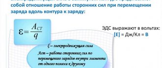
- adjustable source of electromotive force (EMF).
The essence of the experiment is to connect conductors of different lengths. The measured results are entered into a table. It should look something like this:
| First body | Second body | Third body | |||
| U, V | I, A | U, V | I, A | U, V | I, A |
| 1 | 0,5 | 1 | 0,4 | 1 | 0,2 |
| 2 | 1 | 2 | 0,6 | 2 | 0,3 |
| 3 | 1,5 | 3 | 0,8 | 3 | 0,4 |
| 4 | 2 | 4 | 1 | 4 | 0,5 |
After analyzing the table, we can draw a conclusion. If for any body the voltage is divided by the current strength corresponding to it, then the same number will be obtained. Therefore, this relationship is a property of the conductor. For the first it is equal to two, for the second it is five, and for the third it is ten. With equal currents in the third case, the number is larger, which means that this body has greater resistance to the current.
The obtained values are in fact the reciprocal of conductivity. They are designated by the letter R (resistance).
Let's understand what current and resistance are
Let's start with the concept of electric current. In short, electric current as applied to metals is the directed movement of electrons - negatively charged particles. They are usually presented in the form of small circles. In a calm state, they move chaotically, constantly changing their direction. Under certain conditions—the appearance of a potential difference—these particles begin to move in a certain direction. This movement is electric current.
To make it clearer, we can compare electrons to water spilled on some plane. While the plane is motionless, the water does not move. But as soon as the tilt appeared (a potential difference arose), the water began to move. It's about the same with electrons.
This is how you can imagine electric current
Now we need to understand what resistance is and why they have an inverse relationship with current strength: the higher the resistance, the lower the current. As you know, electrons move along a conductor. Usually these are metal wires, since metals have a good ability to conduct electric current. We know that metal has a dense crystal lattice: many particles that are located closely and interconnected. Electrons, making their way between metal atoms, collide with them, which complicates their movement. This helps illustrate the resistance that a conductor provides. Now it becomes clear why the higher the resistance, the lower the current strength - the more particles, the more difficult it is for electrons to overcome the path; they do it more slowly. This seems to have been sorted out.
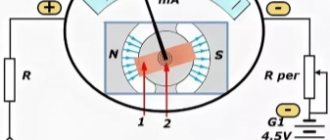
If you want to check this dependence experimentally, find a variable resistor, connect the resistor - ammeter - current source (battery) in series. It is also advisable to insert a switch into the circuit - a regular toggle switch.
Circuit for checking the dependence of current on resistance
By turning the resistor knob you change the resistance. At the same time, the readings on the ammeter, which measures the current, also change. Moreover, the greater the resistance, the less the needle deviates - the less current. The lower the resistance, the more the needle deviates - the greater the current.
Instead of a dial gauge, you can use a digital multimeter in DC measurement mode. In this case, the readings are monitored on the liquid crystal digital display.
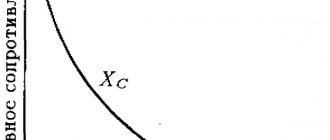
The dependence of current on resistance is almost linear, that is, it is reflected in the graph as an almost straight line. Why almost? This needs to be discussed separately, but that’s another story.
Dependency graph
Based on the results of the experiment, Ohm constructed a graph of current versus resistance, which resembles the left side of a parabola. The modern notation of Ohm's law looks like: I = U / R. It sounds like this: current is directly proportional to voltage and inversely proportional to electrical resistance.
But when developing devices or studying a section of a circuit, scientists and engineers are faced with the task, first of all, of finding out the dependence of current on voltage. Therefore, they construct a graph in which the potential value is plotted along the abscissa axis, and the current strength is plotted on the ordinate axis. As a result, if you plot the corresponding points, you should get a straight line. This suggests that the dependence of the quantities is linear. That is, no matter how many times the voltage increases, the current increases by the same amount.
This type of graph is called current-voltage characteristic (volt-ampere characteristic). But in real measurements, the change in current also depends on temperature. It has been established that when heated, the resistance of the conductor increases. Therefore, the straight line on the current-voltage characteristic will have a smaller angle of inclination. In addition, the current can be of two types:
- constant - the force does not change over time;
- variable - changing according to a sinusoidal law.
The flow of charge carriers for the second type is described by the harmonic law: I(t) = Im * cos (wt + f), where: w – cyclic frequency, f – phase shift relative to voltage, Im – maximum current value. Then the change in voltage over time can be written as follows: U(t) = Um * cos (wt). In this case, Ohm's law will take the form: I = U / Z, where Z is the total resistance of the circuit.
The graph of current versus time, however, like voltage, will be a sinusoid. If we put them aside in one figure, then with active resistance (resistor) the phases of the quantities will coincide with each other. In a circuit containing reactive components, namely capacitance and inductance, the phase of the current will lead and lag the voltage, respectively. The angle of change will be ninety degrees.
Dependency graphs allow you to determine power. This can be done using the formula: P = U * I * cos(f). To construct a power graph, you need to approximate the points of the sinusoid I(t) and U(t) on the t axis, in which the parameters change their sign.
The characteristic P(t) will also be described according to the harmonic law. Moreover, at each point the line will change direction.
Talking about tension
It is equally important to understand what tension is. Let's start with an analogy right away and use water again. Let there be water in the funnel. It leaks through a narrow neck, which creates resistance. If you imagine that a load is placed on the water, the movement of the water will accelerate. This load is tension. And now it is also clear why the higher the voltage, the stronger the current - the stronger the pressure, the faster the water will move. That is, the relationship is direct: more voltage - more current. And it is precisely this situation that is reflected by Ohm’s law - “pressure” is in the numerator (at the top of the fraction).
You can try to imagine the tension in a different way. There are still the same electrons that have accumulated at one edge of the power source. There are few of them on the second edge. Since each of the electrons has some kind of charge, where there are many of them, the total charge is greater, where there are few, less. The difference between the charges is the voltage. This is also easy to imagine. From an electrical point of view, this is a more correct representation, although not accurate.
There are many funny pictures on the topic of Ohm's law that allow you to understand all these phenomena a little better. One of them is in front of you and illustrates how current depends on voltage and resistance. Look what happens: the resistance tries to reduce the current (inverse relationship), and with increasing voltage it increases (direct relationship). This is Ohm's law, but expressed in simple words.
Thanks to the picture, it is easy to understand the dependence of current on voltage and resistance
If you want to be convinced of this dependence, you also need to create a simple chain. But you will need either a regulated power source or several batteries that produce different voltages. Or you can connect several batteries in series - that’s also an option. But you need to change/solder the batteries when the circuit is open (the toggle switch is off).
This circuit uses two measuring instruments: an ammeter is connected in series with the load (resistor in the diagram below), a voltmeter in parallel with the load.
Diagram to illustrate Ohm's law
Since other circuit parameters remain normal, as the voltage increases we will see an increase in current. The more voltage we apply, the more the voltmeter and ammeter needles deviate. If you set out to build a graph, it will be in the form of a straight line. If you install another resistance, the graph will also be in the form of a straight line, but its angle of inclination will change.
Resistance and current
This means that the diameter of the hole matters a lot to the flow of fluid. The diameter of the hole in this case is the cross-section of the pipe, right? What will happen if we insert a hundred-meter pipe into the hole we drilled in the tower? I think it will be no secret to anyone that the flow of water coming out of the pipe will be less than directly from the tower opening. Why is this happening? The point is that water rubs against the walls of the pipe. That is, the walls of the pipe create resistance to the flow of water. Therefore, the longer the pipe, the greater the resistance to flow at the pipe outlet. And the greater the resistance, the less the pressure, we read it as voltage.
Also in electronics. Wires of the same diameter and made of the same material, but of different lengths, also have different resistances. A long wire will have more resistance than a short wire.
And one more nuance.
Which pipe is better for water to flow through? The one with poop stuck on it, or the clean one?
Of course, water will flow better through a clean pipe than through a dirty one. The same can be said about wires. Different metals have different conductivities.
Now let's summarize all of the above. It turns out that the resistance of the wiring depends on the cross-sectional area, its length, and also on the material from which it is made. All this formula will look like this:
A radio element resistor is used as resistance in electronics:
When electric current passes through a resistor, the current in the circuit begins to change. For ease of understanding, from a hydraulic point of view, the resistor can be depicted as a valve damper:
which changes its resistance depending on how much the damper is open.
Let's say we have pressure in the pipe, but the damper is completely closed. In this case, the flow of water stands still and the water does not flow anywhere. Therefore, the flow force in the pipe is zero. But as soon as we open the valve a little, we will experience water movement, which in turn will cause a flow of water. It is not difficult to guess that the more we open the valve, the stronger the flow of water becomes. When the damper is fully open, the water flow will be maximum.
Now let's look at another nuance. With the valve fully closed, we had full water pressure applied to the damper. There is no water flow. This is understandable, the valve does not allow water to flow, although the water is under pressure.
But what happens when we open the damper a little? Will the pressure on the valve itself decrease? Of course. Since the damper resistance area has become smaller. But the most interesting thing also began. There was a movement of water.
What if we open the tap completely and set the valve in this position? What pressure will the flow of water exert on its area?
I think, in an ideal case, we can say that there is none. In a real case, very, very weak pressure will be exerted on the damper area, since it is located parallel to the water flow.
And now another interesting question: what else will the pressure on the damper depend on? From the power of the flow! What is the force of the flow? From pressure! The stronger the water flow, the greater the pressure on the valve. But again, in order for there to be a flow of water, the damper must be open at least halfway, as in this figure:
Classic hydraulics, nothing complicated in theory. Now let's apply all this to electronics.