Why measure resistance?
Insulation is the protection of a wire from the passage of electric current through it. During operation of electrical installations, their design will be subject to the influence of external factors, aging and wear during the heating process. This will negatively affect the functionality of the equipment, so it is necessary to periodically measure the wire insulation resistance.
Resistance measuring device
To measure resistance, you must have a special permit. Electrical wires are tested only by special companies and organizations with qualified specialists. They undergo training and receive the necessary electrical safety ratings.
Important! Carrying out measurements is required to promptly detect damage to equipment. Insulation is essential to safe work on equipment. When the wire is damaged, the installation will be dangerous during operation, as there is a risk of fire.
When you check the wire in time for proper insulation, this will prevent the following problems:
Therefore, it is extremely important to measure the resistance of the wire insulating material.
Resistance measurement (abstract) 2008
Semester work in metrology on the topic “Measurement of resistance.”
Fragments from the abstract
Table of contents
- Introduction
- DC Resistance Measurement Ammeter-Voltmeter Method
- Direct assessment method
- Bridges for measuring DC resistance
- Measuring very high resistances
- Imitance meter
Introduction
Electrical resistance is the main electrical characteristic of a conductor, a value characterizing the resistance of an electrical circuit or its section to electric current. Resistance can also be called a part (more often called a resistor) that provides electrical resistance to current. Electrical resistance is caused by the conversion of electrical energy into other forms of energy and is measured in Ohms.
Resistance (often denoted by the letter R) is considered, within certain limits, to be a constant value for a given conductor and can be defined as.
Where
- R - resistance;
- U is the electrical potential difference at the ends of the conductor, measured in volts;
- I is the current flowing between the ends of the conductor under the influence of a potential difference, measured in amperes.
For practical measurement of resistance, many different methods are used, depending on the measurement conditions and the nature of the objects, the required accuracy and speed of measurements. For example, there are methods for measuring resistance at direct current and at alternating current, measuring high resistances, small and ultra-small resistances, direct and indirect, etc.
The purpose of the work is to identify the main, most common in practice, methods for measuring resistance.
DC Resistance Measurement
The main methods for measuring DC resistance are the indirect method, the direct estimation method, and the bridge method. The choice of measurement method depends on the expected value of the measured resistance and the required measurement accuracy. Of the indirect methods, the most universal is the ammeter-voltmeter method.
Ammeter-voltmeter method
This method is based on measuring the current flowing through the measured resistance and the voltage drop across it. Two measurement schemes are used: measurement of large resistances (a) and measurement of small resistances (b). Based on the results of measuring current and voltage, the required resistance is determined.
For circuit (a), the desired resistance and relative methodological error can be determined using the formulas: .
where Rx is the resistance being measured, and Ra is the resistance of the ammeter.
For circuit (b), the desired resistance and the relative methodological error of measurement are determined by the formulas: .
It is clear from the formula that when calculating the desired resistance using an approximate formula, an error arises because when measuring currents and voltages in the second circuit, the ammeter also takes into account the current that passes through the voltmeter, and in the first circuit, the voltmeter measures the voltage in addition to the resistor also on the ammeter .
From the definition of relative methodological errors it follows that measurement according to scheme (a) provides a smaller error when measuring large resistances, and measurement according to scheme (b) - when measuring small resistances. The measurement error using this method is calculated using the expression: .
“The instruments used for measurement must have an accuracy class of no more than 0.2. The voltmeter is connected directly to the resistance being measured. The current during measurement should be such that the readings are measured on the second half of the scale. In accordance with this, the shunt used to be able to measure current with a device of class 0.2 is also selected. In order to avoid heating the resistance and, accordingly, reducing the accuracy of measurements, the current in the measurement circuit should not exceed 20% of the nominal value.”[4]
The advantage of the ammeter and voltmeter measurement method circuits is that the same current can be passed through the resistor with the measured resistance as in its operating condition, which is important when measuring resistances whose values depend on the current.
Direct assessment method
The direct assessment method involves measuring DC resistance using an ohmmeter. An ohmmeter is a direct reading measuring device for determining electrical active (active resistances are also called ohmic resistances) resistances. Usually the measurement is made using direct current, however, some electronic ohmmeters can use alternating current. Types of ohmmeters: megohmmeters, teraohmmeters, gigaohmmeters, milliohmmeters, microohmmeters, differing in the range of measured resistances.
According to the principle of operation, ohmmeters can be divided into magnetoelectric - with a magnetoelectric meter or magnetoelectric logometer (megaohmmeters) and electronic, which can be analog or digital.
What instruments are there for measuring electrical resistance?
The question often arises as to what devices for measuring resistance are called. To measure electrical resistance, the following instruments are used:
Ohmmeter
Repairing wiring, electrical and radio products involves checking the integrity of cables and searching for broken contacts in connections. In some situations the resistance is infinity, in others it is 0.
Important! To avoid damage, measuring the resistance in a circuit with an ohmmeter is only permissible when the wires are de-energized.
Before measuring resistance with an ohmmeter, you need to prepare a meter. Required:
Megaohmmeter
To measure electrical resistance in the megohm range, a megohmmeter device is used. The operating principle of the device is based on the use of Ohm's law.
To implement such a law in a product, you will need:
Important! The implementation of a megohmmeter requires a minimum number of elements. Such products function properly for a long time. The voltage in the devices will be supplied by a direct current generator, the values of which vary.
Working on electrical equipment with such a device carries an increased danger due to the fact that the device will generate high voltage and there is a risk of injury. Work with the megohmmeter is carried out by personnel who have studied the manual for using the device and the safety rules when working on electrical equipment. The specialist must have an access group and from time to time be tested for knowledge of the rules of work in the installation.
Multimeter
Multimeters are universal and specialized, designed to perform one action, but carried out as accurately as possible. In the device, the ohmmeter is considered only an element of the device; it must be turned on in the required mode. Multimeters require certain skills to use - you need to know about their correct connection and interpretation of ready-made information.
In appearance, digital and analog devices are easy to distinguish: in digital, information is displayed on the monitor in numbers, in analog, the dial is graduated and an arrow points to the indicators. A digital multimeter is easier to use, since it will immediately show ready-made data, while the readings of an analog one need to be deciphered.
Active resistance measurement
Laboratory work
METHODS FOR MEASURING THE RESISTANCE OF LINEAR RESISTORS AND CHARACTERISTICS OF NONLINEAR
ELEMENTS
Purpose: To become familiar with existing methods for measuring the resistance of linear resistors and the characteristics of nonlinear elements. Master practical skills in performing experiments and processing measurement results.
Equipment: Laboratory installation containing measuring instruments:
• M830V multimeters;
• AC bridge R 333;
• power supply VSP - 30.
Theoretical part
Electrical circuits represent a set of electrical energy sources and loads connected in a certain way through which direct or alternating current flows. From the point of view of the ratio of the sizes of the circuits and the operating wavelength of the electrical oscillations that take place in them, circuits with concentrated and distributed parameters (constant) are distinguished.
Radioelectronic circuits whose dimensions are much smaller than the operating wavelength are called circuits with lumped parameters. The properties of these circuits are practically independent of the configuration of the terminals (electrodes) of active and passive elements and the size of the connecting wires. Radio-electronic circuits, the physical dimensions of which are commensurate with the operating wavelength of oscillations, belong to circuits with
distributed parameters. Each element or connecting wire of such a circuit has resistance (active, i.e. irreversible, power losses), inductance and capacitance. Such circuits are often called long lines or microwave paths.
In electrical circuits with lumped parameters, general-purpose linear components are widely used: resistors, inductors and capacitors. Under certain assumptions, these elements can be considered as linear passive two-terminal networks, characterized by certain ideal parameters - resistance R (the reciprocal of resistance - conductivity Y), inductance L, capacitance C.
When measuring, however, it is not always possible to determine the value of a particular parameter corresponding to the ideal, perfect form of the element. Therefore, it is necessary to know a number of secondary parameters of the elements, for example: quality factor Q, loss tangent δ, characteristic resistance ρ.
Methods for measuring electrical parameters of circuits with lumped parameters are very diverse, and the instrumentation includes mainly electronic devices, so the designation of measuring instruments may vary depending on the system used. Most often, domestic electronic meters of circuit parameters are designated as E6 - E7. A large group of instruments (some bridges and measuring lines) are designated by the letter “P”.
Depending on the type of the measured quantity, the required accuracy of the result, the range of operating frequencies and other conditions, various methods and measuring instruments are used to measure the parameters of elements with lumped constants. The most common measurement methods here are: the ammeter-voltmeter method, the direct assessment method, the bridge method, the resonant method and the
discrete counting (digital method).
The main parameters of long lines, by analogy with circuits with lumped constants, are linear
active resistance, inductance and capacitance. However, unlike circuits with lumped constants, these parameters do not have such a clear physical meaning, and therefore are not measured. At the same time, all the main elements of microwave paths are analogues of the two- and four-terminal networks that make up circuits with lumped constants. This analogy allows us to consider the parameters of microwave paths as the parameters of two- and four-terminal networks. Instruments designed to measure the parameters of circuits with distributed constants are classified depending on the nature of the specific measurements and the type of measured quantities.
Active resistance measurement
The values of measured active resistances range from 10 8 to 1010 Ohms; serially produced devices often cover the range from 0.001 to 109 ohms. Active resistance can be measured at both direct and alternating current. Measuring active resistance on alternating current turns out to be advisable in circuits where there are losses during magnetization reversal (circuits with steel cores - inductors, chokes, transformers).
Among the industrial methods for measuring active resistance at direct current, the following can be distinguished:
•methods based on the use of one ammeter or volt meter (can be electromechanical or electronic devices);
• ratiometric methods;
• bridge methods (analog and digital devices).
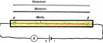
The ammeter-voltmeter method is based on the use of Ohm's law. Figure 1 shows the implementation of this method.
a) b)
Rice. 1.
Measuring active resistances using the ammeter-voltmeter method
In the circuit in Fig. 1, a, the deflection of the magnetoelectric milliammeter needle is proportional to the current (source voltage E)
(1)
and inversely proportional to the measured resistance Rx. This circuit measures fairly large resistances (from 1 Ohm to 200 MOhm). Before measurements, the clamps are closed with the key K and the resistor is used to set such a current so that the needle deviates to the full scale, which corresponds to the 0 Ohm point. A similar circuit for measuring active resistance is widely used in combined devices - so-called testers.
To measure small resistances (0.01... 100 Ohms), the circuit shown in Fig. 1, b is used. The voltmeter readings are determined by the formula
(2)
provided that , ,i.e. there is a direct dependence of voltage (voltmeter readings) on the measured resistance. Before measurement, the arrow on the device is aligned with the mark c with the clamps x open.
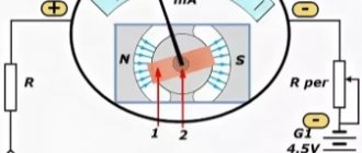
The accuracy of both methods is low, the measurement error is about 1.5...2%. There is a direct dependence of the readings on the supply voltage E and its stability. The use of a magnetoelectric ratiometer allows you to reduce the influence of the power source E on the accuracy of active resistance measurements. The device and switching circuit of the magnetoelectric ratiometer are presented in Fig. 2.
a) b)
Rice. 2.
Magnetoelectric logometer: a
- device;
b
- connection diagram.
A magnetoelectric ratiometer is a system of two frames rigidly fastened together, placed in the uneven field of a permanent magnet (Fig. 2, a). The unevenness of the magnetic field is achieved through a special configuration of the pole pieces. The field is made uneven so that the torques applied to the frames depend not only on the currents flowing in the frames, but also on the position of the frames in the magnetic field, i.e.
(3)
where I1, Ix are currents flowing within the frame; , are the values of flux linkages with their corresponding frames. Since the torques of the frames with the current flowing in them are directed in opposite directions, the equilibrium position will occur under the condition that M1 = M2; = and, therefore, the angle of deflection of the moving system is determined by the ratio of currents
. (4)
For the diagram in Fig. 2, b
(5)
where is the frame resistance; - exemplary resistance.
Thus, the ratiometer readings are practically independent of supply voltage fluctuations, since
.
(6)
Such a linear dependence makes it possible to create laboratory ratiometers with a measurement error not exceeding 0.5%. The insensitivity of the ratiometer to fluctuations in supply voltage also made it possible to develop a class of devices powered by generators whose rotor is rotated manually.
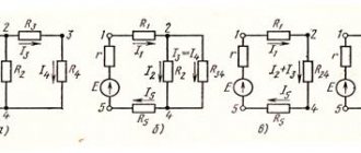
Another implementation of the ammeter-voltmeter method is shown in Fig. 3.
Fig.3.
Circuits for measuring resistance using the ammeter-voltmeter method
Using Ohm's law it is not difficult to obtain the desired value of the unknown resistance.
For the diagram in Fig. 3. a.
.
(7)
For the circuit Fig. 3.b.
where: U, I - voltmeter and ammeter readings;
, (8)
, are the internal resistances of the voltmeter and ammeter, respectively.
When determining the unknown resistance Rx using the ammeter-voltmeter method, there is a methodological component of the total error
(9)
where is the true value of the resistor resistance, which can be taken as
measurement result using a high-precision measuring instrument. In practice, a metrological margin (accuracy margin) of at least three times is accepted. In this work, bridge P 333 should be used for determination.
The relative methodological error will be
.
(10)
Bridge meter circuits
The main methods for measuring parameters R, L, C on alternating current are bridge and resonant. Bridge measurement methods are more accurate, but can only be used over a limited frequency band. There are several types of bridge schemes: four-arm, six-arm (double), balanced,
unbalanced and interest. The control of these bridges can be either manual or automatic. The most widespread schemes are four-arm balanced bridges. A generalized block diagram of such a bridge is shown in Fig. 4, a.
Rice. 4, a.
Generalized block diagram of a four-arm bridge
The resistances of a four-arm bridge in the general case are complex:
.
(11)
The equilibrium conditions of such a bridge will be determined by two equations:
; (12)
. (13)
To fulfill these conditions, it is necessary to have two elements with adjustable parameters in the bridge arms. These parameters are most convenient for making active resistances. A reference capacitor with capacitance C0 with low losses is used as an element that provides the necessary phase shift.
A simplified block diagram of a four-arm balanced bridge for measuring active resistances is shown in Fig. 4, b.
A magnetoelectric, electronic or digital null indicator (NI) is included in the diagonal of the bridge, the current in which must be set equal to zero at the time of measurement. According to the bridge equilibrium condition (12), it is necessary that equality be satisfied, from which the unknown resistance can be expressed by the following formula:
.
(14)
To achieve bridge equilibrium, it is enough to have one adjustable parameter (resistor R4), as shown in Fig. 4, b. The limits of measured resistance for such bridges range from 10 2 to 107 Ohms. Measurement errors range from hundredths of a percent to several percent, depending on the measurement range. The smallest errors lie in the range from 100 Ohms to 100 kOhms. At low measured resistances, the resistance of the connecting wires contributes to the measurement error; at large resistances, leakage resistance contributes.
The circuit presented in Fig. 4 can be created in a digital version. For this, an adjustable resistor is made in the form of a set of a series of resistances made in accordance with the binary decimal code. The resistances are alternately connected to the arm of the measuring bridge until the circuit is balanced. The position of the keys characterizes the code of the measured value, which then enters the digital readout device.
Measurement Safety Precautions
Even when there is a need to measure the insulation resistance of a wire in domestic conditions, before using a megohmmeter you need to familiarize yourself with the safety requirements. Main rules:
The rules are simple, but the safety of the employee will depend on them.
Security requirements
To evaluate the functionality of an electrical wire or wiring, it is necessary to measure the resistance of the insulating material. For these purposes, special measuring instruments are used. They will supply voltage to the measured electrical circuit, after which the data will be displayed on the monitor.
Source
Preparing an Ohmmeter for Measurements
Repair of electrical wiring, electrical and radio engineering products consists of checking the integrity of the wires and searching for contact failure in their connections.
In some cases, the resistance must be equal to infinity, for example, insulation resistance. And in others it is zero, for example, the resistance of wires and their connections. And in some cases it is equal to a certain value, for example, the resistance of the filament of a light bulb or heating element.
Attention! In order to avoid failure of the Ohmmeter, it is allowed to measure the resistance of circuits only when they are completely de-energized.
You must unplug the plug from the socket or remove the batteries from the compartment. If the circuit contains electrolytic capacitors of larger capacity, then they must be discharged by shorting the capacitor terminals through a resistance of about 100 kOhm for a few seconds.
As with voltage measurements, before measuring resistance, it is necessary to prepare the device. To do this, you need to set the device switch to the position corresponding to the minimum measurement of the resistance value.
Before measurements, you should check the functionality of the device, since the batteries may be bad and the Ohmmeter may not work. To do this, you need to connect the ends of the probes together.
The tester's needle should be set exactly to the zero mark; if it is not set, then you can turn the "Set" knob. 0". If this does not work, you need to replace the batteries.
To test the continuity of electrical circuits, for example, when checking an incandescent light bulb, you can use a device whose batteries are dead and the needle does not set to 0, but reacts at least a little when the probes are connected. It will be possible to judge the integrity of the circuit by the fact that the arrow is deflected. Digital devices should also show zero readings, a deviation in tenths of ohms is possible due to the resistance of the probes and the transition resistance in the contacts connecting them to the terminals of the device.
When the ends of the probes are open, the tester arrow should be set to the point indicated on the scale ∞, and in digital instruments, the overload will blink or the number will be displayed 1
on the indicator on the left side.
The ohmmeter is ready for use. If you touch the ends of the probes to the conductor, then if it is intact, the device will show zero resistance, otherwise the readings will not change.
Expensive models of multimeters have a circuit continuity function with audio indication, indicated in the resistance measurement sector with a diode symbol. It is very convenient for testing low-impedance circuits, such as twisted pair cables for the Internet or household electrical wiring. If the wire is intact, then the continuity is accompanied by a sound signal, which eliminates the need to read readings from the multimeter indicator.
Instruments for measuring resistance
It is worth opening any textbook on electrical engineering and it immediately becomes clear that almost all electrical quantities are named after the great physicists of the past: Volt, Ampere, Henry, Ohm, Farad, Tesla, Hertz. Of course, it’s a shame that Russian physicists are not on this list.
The German physicist Georg Ohm was the first to introduce the concept of resistance. In his honor, the unit of measurement of resistance was called “Ohm”. This quantity is represented by the Greek letter omega - Ω.
Previously, radioelements were called “resistance” and only much later the word resistor came into use. Before the introduction of markings using colored stripes, all necessary data was applied directly to the resistor body. In the technical literature you can find the following designations: kilo-ohm and mega-ohm, which means a thousand ohms and a million ohms, respectively. On circuit diagrams, next to the resistor designation, you can insert the following inscriptions: 4K7 - four and seven kiloohms (4.7 kOhm) or 1M2 - one and two megaohms (1.2 MOhm). On foreign diagrams, “ Ohm ” is written as “ Ohm ”.
To measure resistance, a device called Ohmmeter . Instruments that measure only resistance are usually not used in amateur radio practice. Such high-precision instruments are used in factories that produce resistors to determine the value with a certain error or in research laboratories.
But everyone knows such a thing as a tester or multimeter. Such devices combine a voltmeter, an ammeter and an ohmmeter + the functionality is complemented by the ability to check diodes or measure temperature. It all depends on the cost and performance of the device. Multimeters are either dial or digital. Each of them has its own characteristics, advantages and disadvantages.
Measuring resistance with an ammeter and voltmeter
The resistance value found from the ammeter and voltmeter readings (Fig. 7-30) is greater than the actual value of the desired resistance rx
by the value of the ammeter resistance, since in the circuit in Fig.
A 7-30 voltmeter measures the sum of the voltages across the resistance rx
and the ammeter. If the measured resistance is significantly greater than the resistance of the ammeter, the measurement error will be small.
Resistance value
r"
x =
U
/
I
Fig. 7-30.
Connection diagram for measuring resistance with an ammeter and a voltmeter (for high resistances).
found from instrument readings (Fig. 7-31), is less than the actual value of the desired resistance r
x since the ammeter measures the sum of the currents in the resistance
r x
and in the voltmeter. If the measured resistance is significantly less than the resistance of the voltmeter, the error will be small.
Rice. 7-31.
Connection diagram for measuring resistance with an ammeter and a voltmeter (for lower resistances).