3. Characteristics of the measured quantity, standard values of the measured quantity.
3.1. The object of measurement is electrical equipment and wiring with voltages up to and above 1000 V
3.2. The measured quantity is the insulation resistance.
3.3.
The measured insulation resistance of electrical equipment with voltages up to 1000 V must not be lower than the minimum permissible value given in the table. Minimum permissible values of insulation resistance of elements of electrical networks with voltages up to 1000 V
| Item name | Megger voltage, V | Insulation resistance, MOhm | Note |
| Electrical products and devices for rated voltage, V: | Must comply with manufacturers' instructions, but not less than 0.5 | When taking measurements, semiconductor devices in products must be shunted | |
| up to 50 | 100 | ||
| over 50 to 100 | 250 | ||
| over 100 to 380 | 500-1000 | ||
| over 380 | 1000-2500 | ||
| Switchgears, boards and conductors | 1000-2500 | at least 1 | Measurements are taken on each section of the switchgear |
| Electrical wiring, including lighting networks | 1000 | not less than 0.5 | Insulation resistance measurements in particularly hazardous rooms and outdoor installations are carried out once a year. In other cases, measurements are made once every 3 years. When making measurements in power circuits, measures must be taken to prevent damage to devices, especially microelectronic and semiconductor devices. In lighting networks, lamps must be unscrewed, sockets and switches connected. |
| Secondary circuits of switchgears, power supply circuits for drives of switches and disconnectors, control circuits, protection circuits, automation, telemechanics, etc. | 1000-2500 | at least 1 | Measurements are made with all connected devices (coils, contactors, starters, switches, relays, instruments, secondary windings of voltage and current transformers) |
| Cranes and elevators | 1000 | not less than 0.5 | Produced at least once a year |
| Stationary electric stoves | 1000 | at least 1 | Performed when the stove is heated at least once a year |
| DC buses and voltage buses on control panels | 500-1000 | at least 10 | Produced with disconnected circuits |
| Control, protection, automation, telemechanics, excitation circuits for DC machines with a voltage of 500-1000 V connected to the main circuits | 500-1000 | at least 1 | The insulation resistance of circuits with voltages up to 60 V, powered from a separate source, is measured with a megohmmeter for a voltage of 500 V and must be at least 0.5 MOhm |
| Circuits containing devices with microelectronic elements designed for operating voltage, V: | |||
| up to 60 | 100 | not less than 0.5 | |
| above 60 | 500 | not less than 0.5 |
Why is insulation resistance measured?
In this article I will try to answer all the questions related to this type of test, if suddenly there are any questions, they can be written in the comments under the article. Below is a list of topics that the article is divided into, they are also links to the part of the page where this is discussed.
- Why is insulation resistance measured?
- Who can request a protocol or conduct tests;
- Work order;
- What instruments are used to measure;
- Test frequency;
- What documents regulate testing;
- Acceptable insulation resistance values;
- Sample protocol.
Why is insulation resistance measured?
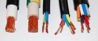
This type of electrical measuring work is one of the most basic. It is carried out in order to identify manufacturing defects in the cable, damage that occurred during the installation of the cable, as well as its careless operation. As insulation ages over time, its properties deteriorate. If the cable was repeatedly overloaded during operation or short circuits occurred on the line, this also negatively affects the service life of the insulating layer. In fact, testing allows you to prevent dire consequences, such as:
- Fire caused by a short circuit;
- Electrical shock to people, which can be fatal;
- Failure of electrical equipment, especially sensitive microelectronics;
It is good practice to check the cable in the coil or on the drum before laying it, in order to avoid inconvenient situations associated with manufacturing defects. It is especially sad to lay a fairly large piece of bad cable, large weight and cross-section.
Who can request a protocol or conduct tests
As a rule, the following services require the coveted piece of paper or a protocol:
- Administration or service of the chief power engineer of shopping and business centers;
- A management company that manages residential or non-residential real estate, HOAs, SNTs, etc.;
- The Customer or General Contractor for electrical installation work or the technical supervision hired by him to check that everything is done correctly before the final payment has been made;
- When inspecting objects in operation, a firefighter or an inspector from the Ministry of Emergency Situations may require;
- When commissioning large facilities - a representative of Rostechnadzor;
- Insurance company, when insuring real estate, especially large objects such as warehouses.
Work order.
The real test is carried out with the load completely disconnected, since otherwise nothing will work; even a telephone charger plugged into the socket will not allow the test to be completed. Regardless of the type of object, such work is planned in advance so that the customer can provide access to all premises and the ability to disconnect all electrical appliances, including disconnecting lamps, from the supply line. Let's consider the procedure for carrying out work using the example of a small office center consisting of an ASU, several floors with electrical distribution panels. As a rule, it all starts with measuring the main lines from the building's ASU to the electrical distribution panels. Next, from the electrical distribution panels, the power lines for sockets and lighting, as well as other electrical equipment, are checked.
Each line is measured for 1 minute. If the line is 3-wire (220V), then 3 measurements are made: phase conductor - relative to the neutral one, phase conductor - relative to the grounding one, zero relative to the grounding one. If the line is 5-wire (380V), then much more measurements are made, namely 10: phase1 - phase2, phase1 - phase3, phase2 - phase3, phase1 - zero, phase2 - zero, phase3 - zero, then also each phase conductor relative to the grounding (PE), as well as zero relative to it. The actual work requires quite a lot of time.
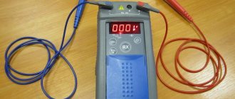
What instruments are used to measure
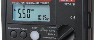
Since insulation resistance is determined in megaohms (Mohm), a special device, a megohmmeter, is used for measurements. Such a device is available in every electrical measuring laboratory, even in large electrical installation organizations. It can be either combined, which has functions for other measurements, or as a separate device such as:
- E6-24;
- ES0202/2G;
- MI 3121H.
For official testing, it is necessary that the device is in the state register and also has a valid verification. Naturally, in an electrical laboratory that checks objects every day, there are no problems with this. For an electrical installation organization that checks only for itself, for example, a cable after installing a coupling, after or before laying, any working megohmmeter will be sufficient, since they do not need to submit an official report.
Test frequency;
The frequency of work is prescribed in the PTEEP. For the main objects it is as follows:
- When commissioning the facility;
- On cranes and elevators - at least once a year;
- Stationary electric stoves - at least once a year;
- In particularly hazardous rooms and outdoor electrical installations - at least once a year;
- In all other cases - at least once every 3 years;
Despite the frequency described above, if you are a tenant, then of course you need to look at the lease agreement, it may stipulate a different frequency and the test program itself; often the administration of shopping centers sets the frequency once a year, even if you do not have premises related to especially dangerous, also requires mandatory thermal imaging inspection of electrical panels and updating of single-line diagrams. Naturally, no one forbids carrying out inspections more often, it will only be better, but for missing a check you can get a fine, even with the suspension of activities, at the discretion of the inspector.
What documents regulate testing?
PTEEP, GOST 50571 test section, Article 9.11 of the Administrative Code of the Russian Federation. PUE. Technical regulations of lessors, RD 34.45-51.300-97 scope and standards for testing electrical equipment.
Acceptable insulation resistance values
- General purpose electrical wiring - at least 0.5 Mohm;
- Control circuits - at least 1 Mohm;
- Cranes, elevators, electric stoves, stator windings of electric motors - at least 1 Mohm;
If the device readings were no more than 1 MΩ, then it is necessary to test the cable with increased voltage of industrial frequency 50 (Hz).
In reality, megohmmeter readings from 5 megohm and below, while changing sharply during the measurement process, are practically shooting through in some place in the cable, this can be clearly seen in the video at the end of the article.
Sample protocol
I am attaching a sample protocol, as well as a picture.
In any case, in reality the situation is such that if any emergency situations occur, especially a fire, as a rule they begin to raise documents and check whether the insulation resistance was measured in a timely manner and if it was not, then this is one of the options to blame everything on it.
Naturally, checking the insulation alone is not enough; it is advisable to check the object comprehensively, since in the event of a short circuit it is important that the circuit breaker operates instantly (0.4 seconds for group networks). To do this, the resistance of the phase-zero loop is measured.
Measurement conditions
4.1 The measurement is carried out indoors at a temperature of 25±10°C and a relative air humidity of no more than 80%, unless other conditions are provided for in the standards or technical specifications for cables, wires, cords and equipment.
4.2 The value of the electrical insulation resistance of the connecting wires of the measuring circuit must exceed at least 20 times the minimum permissible value of the electrical insulation resistance of the product under test.
4.3. It is recommended to measure the insulation characteristics of electrical equipment using the same type of circuits and at the same temperature. Comparison of insulation characteristics should be made at the same insulation temperature or similar values (temperature difference no more than 5°C). If this is not possible, then a temperature recalculation must be made.
Safety requirements
ATTENTION! Do not start measurements without making sure that there is no voltage on the object being measured.
5.1. Before starting tests, it is necessary to make sure that there are no people working on that part of the electrical installation to which the test device is connected, to prohibit persons located near it from touching live parts and, if necessary, to set up security.
5.2. Measuring the insulation resistance with a megohmmeter should be carried out on disconnected live parts from which the charge has been removed by first grounding them. Grounding from live parts should be removed only after connecting the megohmmeter.
5.3. When measuring the insulation resistance of live parts with a megohmmeter, the connecting wires should be connected to them using insulating holders (rods).
5.4. When working with a megohmmeter, touching the live parts to which it is connected is not allowed. After completion of work, the residual charge should be removed from live parts by briefly grounding them.
Carrying out measurements and measurements of insulation resistance of grounding and electrical networks
The first grounding check and measurement of the insulation resistance of cable and wire products is carried out directly at the manufacturing plant. Naturally, if the cable is not counterfeit, which once again brings us back to the issue of the quality of cable products and the reliability of suppliers.
Further, resistance measurements must be performed before starting any installation work and before commissioning (first start-up) of the power supply system. In this case, measurements of insulation resistance are necessary to identify possible damage to the insulation of cables and wires that occurred during installation work. It is also mandatory to measure the insulation resistance before and after repair work on power supply lines.
After commissioning of structures, insulation resistance in Moscow is checked once a year. This allows you to timely detect malfunctions and damage to cables and wires and, accordingly, prevent in advance the possibility of various emergency situations.
Carrying out measurements and measurements of grounding insulation resistance, electrical networks and electrical wiring in Moscow and the Moscow region under a contract.
Preparing to take measurements
To perform measurements, megohmmeters ESO202/1-G or ESO202/2-G are used, depending on the requirements for the test voltage.
6.1. Before starting measurements, it is necessary to study the electrical installation of the building and make sure that there is no voltage on the tested object, take measures to prevent access to the tested object by persons not participating in the tests, and, if necessary, assign an observer. Disconnect electrical appliances, remove fuses, disconnect devices (circuit breakers, switches), disconnect electronic circuits and electronic devices, electrical parts of an electrical installation with reduced insulation or reduced test voltage.
6.2. Set the measuring voltage switch on the megohmmeter to the desired position (in accordance with the test voltage requirements), and the range switch to position I.
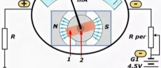
Scheme for checking insulation with a megohmmeter
Resistance measurement:
Cable insulation measurement:
6.3. Check the serviceability of the megohmmeter. When the generator handle is rotated, the “VN” indicator should light up.
Measuring the insulation resistance of electrical equipment
Typically, measuring cable insulation resistance, the price most often depends on the number of cable lines. Resistance measurements are carried out at voltages up to and above 1000 V. Insulation resistance measurements in such networks are carried out according to the following scheme.
- Main line – general distribution boards.
- General distribution boards – apartment distribution boards.
- Switches - lamps (checking the insulation resistance of lamps is included in the measurement of insulation resistance).
Taking measurements
7.1. After making sure that there is no voltage on the object, connect the object to the “rx” sockets. If shielding is necessary, to reduce the influence of leakage currents, connect the object’s screen to socket “E”. To reduce the time it takes to establish readings before measuring resistance on scale II for 3-5 seconds. Rotate the generator handle with the “rx” terminals short-circuited.
7.2. To carry out measurements, rotate the generator handle at a speed of 120-144 rpm.
7.3. The reading of the electrical insulation resistance values during measurement is carried out after 1 minute from the moment the measuring voltage is applied to the sample, but not more than 5 minutes, unless other requirements are provided for in the standards or technical conditions for specific cable products or other equipment being measured. Before re-measurement, all metal elements of the cable product must be grounded for at least 2 minutes.
7.4. When measuring the insulation parameters of electrical equipment, random and systematic errors must be taken into account due to the errors of measuring instruments and apparatus, additional capacitances and inductive couplings between the elements of the measuring circuit, the effect of temperature, the influence of external electromagnetic and electrostatic fields on the measuring device, method errors, etc.
7.5. The electrical insulation resistance of multi-core cables, wires and cords must be measured:
- for products without a metal sheath, screen and armor - between each current-carrying conductor and the remaining conductors connected to each other or between each conductive conductor; residential and other conductors connected to each other and grounding.
- for products with a metal shell, screen and armor - between each current-carrying conductor and the remaining conductors connected to each other and to the metal shell or screen, or armor.
How to make and carry out measurements and measurements of insulation resistance in Moscow and the Moscow region?
It should be noted that it is necessary to use exclusively specialized equipment and strictly adhere to safety precautions. This will allow all tests to be carried out successfully and without injury.
Stage 1 - carry out a visual measurement of the insulation resistance of the electrical wiring. Specialists inspect wires, cables and distributors for possible damage, paying special attention to those areas of the wiring where the insulation has melted. The presence of such places may be the first signal of possible malfunctions in the power supply system.
Stage 2 - check insulation resistance measurements - disconnecting the power supply system from the current source. This stage is necessary to ensure the safety of the work being carried out.
Stage 3 - check the insulation resistance measurements - in fact, the measurements themselves, which are carried out using a special device - a megger (more on the features of its use below).
Stage 4 - checking the insulation resistance - drawing up a detailed Technical report on the test results and developing recommendations for troubleshooting.
Stage 5 - carry out work on measuring insulation resistance - providing the customer with mandatory documents: a defect report, a certificate of completion of all work, a load map, technical reports and a protocol of electrical measurements.
It should be noted that the results of the insulation resistance test are significantly influenced by many factors, such as ambient temperature, humidity level, etc.
Registration of test results (measurements).
8.1. The results of the inspection are reflected in the protocol of the appropriate form.
8.2. A list of noticed deficiencies must be presented to the customer so that measures can be taken to eliminate them.
8.3. The test and measurement report is drawn up in the form of an electronic document and stored in the appropriate database. The second copy of the protocol is printed and stored in the archive of the electrical measuring laboratory.
8.4. Copies of test and measurement reports must be stored in the archives of the electrical laboratory for at least 3 years.