Measuring insulation resistance with a megohmmeter [edit | edit code]
The insulation resistance characterizes its condition at a given time and can vary from the influence of external conditions, since it depends on a number of factors, the main influencing factors being the temperature and humidity of the insulation at the time of measurement.
In GOST 183-74, standards for the permissible minimum insulation resistance are not standardized, since there are no absolute criteria for the minimum permissible insulation resistance. They are usually established in standards for specific types of machines or in technical specifications for products or materials with a mandatory indication of the temperature at which measurements must be carried out, and the method for recalculating the measured resistance, reduced to standard conditions, if the measurements were carried out at a different temperature of the windings.
Measuring the insulation resistance of windings establishes the possibility of testing insulation with operating high voltage without the risk of electrical breakdown of insulation that is serviceable but has high humidity.
The measurements are carried out with a megohmmeter, the test voltage of which is selected depending on the rated operating voltage of the insulation under test. For devices with a rated voltage of up to 500 V (660) V, 500 V megohmmeters are used, for devices with voltages up to 3000 V - 1000 V megohmmeters, for devices with a rated voltage of 3000 V and more - 2500 V megohmmeters and higher.
The degree of moisture content of the insulation is judged not only by the resistance value at the time of measurement, but also by the nature of the change in the megohmmeter reading during the measurement process, which is usually carried out within 1 minute. In this case, the readings of the device are recorded 15 s after applying the test voltage (time sufficient to establish the readings), this resistance is designated R15″ and at the end of the measurement - 60 s after the start – the designation R60″. The ratio of these readings R60″/R15″ is called the absorption coefficient
(KA). Its value determines the ratio of the polarization current to the leakage current through the dielectric - the winding insulation. With wet insulation, KA is close to 1. With dry insulation, the value of R60″ is 30-50% greater than the value of R15″.
The megohmmeter also measures the insulation resistance of thermal converters built into electrical machines and the insulation resistance of wires connecting the thermal converters to external terminals.
The insulation resistance of thermal converters is measured relative to the device body and relative to the machine windings. This insulation is not designed to operate at high voltages in the machine windings, so its resistance should be measured with a device with a rated voltage of no higher than 250 V.
In addition to the insulation resistance of the windings, when testing at the installation site of the machine, the insulation resistance of the bearings is also measured, which is installed to prevent the flow of bearing currents in machines with riser bearings [ clarify
] .
Thus, the insulation resistance of different windings of the same machine, having different rated voltages, for example, the stator and rotor windings of a synchronous motor, must be measured with different megohmmeters with different rated voltages, or with a megohmmeter with a switchable test voltage.
Electrical resistance can be measured with various instruments. The megohmmeter has become the most popular among such devices. Judging by the name of the device, it can be determined that its unit of measurement is megaohms. It is primarily used to measure large resistance values, electrical circuits , and dielectric insulation used for cables, wires , electric motors , transformers and other electrical installations.
To use a megohmmeter in work, you must first study its operating principle, design and technical parameters, since there are specific features when using such a device.
Kinds
There are two main types of megohmmeters, differing in the type of power source and measurement method.
Analog
Such devices are also called pointer devices. They have an individual dynamo, which is activated by turning the handle, as well as a graduated scale with a dial indicator. The measurement is carried out based on the magnetoelectric principle. The pointer is fixed on the same axis with a frame coil located in the magnetic field of a permanent magnet.
When current flows through the coil, it deflects by a certain angle, depending on the magnitude of the current flowing. This action occurs according to the law of electromagnetic induction. The pointer megohmmeter is unpretentious in operation, reliable, although it is considered an outdated device, has a large mass and significant overall dimensions.
Digital
Modern digital megohmmeters have a built-in powerful pulse generator operating on field-effect transistors . Such devices are equipped with an individual power source, in the form of an AC adapter that converts alternating current to direct current, or a rechargeable battery . The measurement is performed by a special amplifier by comparing the voltage drop in the circuit under test with a reference resistance.
Read also: How to distinguish tin from lead
The measurement results are displayed on a digital screen. It is possible to save the results in memory for future data comparison. The electronic megohmmeter is lightweight and small in size, allowing you to make many different electrical measurements. However, to work with such a device, highly qualified personnel are required.
Operating principle and device
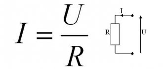
The operation of a megohmmeter is to use Ohm's law , which is described by the formula: I = U / R , where I is the current, U is the voltage, and R is the resistance. The device of this device includes a calibrated voltage source, an ammeter and terminals to which special measuring probes are connected.
Older analog instruments have conventional hand-held generators with a crank to operate them, while newer models use external or internal power sources in the form of a battery or power supply. The amount of power at the generator output and the voltage can vary over a wide range, or be constant, depending on the design of the device. The megaohmmeter kit includes measuring probes, which consist of wires with tips: on one end of the probe there is a tip for insertion into the device socket, and on the other there is a “crocodile” for reliable contact.
Before measurement, the probes are inserted into the sockets on the device, then connected with crocodile clips to the object being measured. When performing a measurement, the generator generates high voltage by rotating the handle. Voltage is supplied to the object being measured, and the measurement results are displayed on the screen of a digital device or on the scale of a pointer megohmmeter.
How to use a megohmmeter correctly
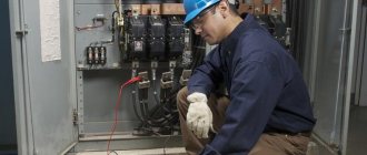
During operation, the device produces high voltage that is dangerous to humans - from 500 to 2500 volts. Therefore, the use of the device must be approached with extreme caution. In industrial production, persons with an electrical safety group of at least third are allowed to work with it.
Before taking measurements, the circuits being tested should be de-energized. If measurements are planned to be made in an apartment, then you should turn off the circuit breakers in the distribution board, then turn off all connected devices in the apartment.
If groups of sockets are checked, then all inserted device plugs should be removed from them. When checking lighting circuits, it is necessary to unscrew the light bulbs, since they are not designed for such high voltage and can burn out. When testing the insulation of electric motors, they should also be disconnected from the network.
Next, the circuits being tested should be grounded. To do this, a stranded wire in insulation with a cross-section of more than 1.5 mm 2 is connected to the grounding bus, which is portable grounding.
Safety requirements
Even if you use a megohmmeter at home, before work you should study the requirements for safe work practices.
There are several basic rules:
- Probes should only be held by insulated handles limited by stops.
- Before connecting the probes to the circuit being measured, you should make sure that the voltage supply to the device is turned off and that there are no people near the line being measured who could accidentally become energized.
- The next step is to remove the residual voltage by touching a portable ground to the circuit being measured. Grounding is turned off only after installing the probes.
- After each measurement, it is necessary to remove residual voltage from the probes by connecting the probes to each other.
- After the measurement, grounding should be connected to the tested conductor to remove the residual charge.
- All work must be done with rubber gloves.
These simple rules must be followed, since the safety of people depends on it.
Rules for connecting probes
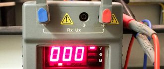
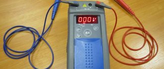
There are three sockets on the device body. They are designated by the symbols “ E ”, “ L ” and “ Z ”, which means screen, line and ground, respectively. The megaohmmeter kit contains three probes. On one of them, two tips are connected on one side. This probe is used when it is necessary to exclude leakage current, and is connected to the shielded sheath of the cable, if available. The remaining probes are inserted into the sockets corresponding to the markings of the probes with the same letters.
All probes have stops. When taking measurements, you should grasp the probes as far as they will go so as not to accidentally touch the live parts with your fingers.
If it is necessary to measure only the insulation resistance, without taking into account the screen, then two single probes are connected. Of these, one is inserted into the “ Z ” terminal, and the second into the “ L ” terminal. The second sides of the probes should be connected with “ crocodiles ”:
- To the wires being tested, if necessary, test for breakdown between the wires.
- To the grounding and current-carrying conductor, if you need to test the “ground fault”.
Usually, a check is made for insulation breakdown and the value of its resistance, and a check of the shielded sheath is rarely performed, since cables with a shield are almost never used in apartments. When using the device, the main rule is to remove the residual charge, as well as to be careful, as there is a danger of getting under high voltage.
Measurement procedure
- Before starting the measurement (using the indicator ), you should make sure that there is no voltage on the line being measured.
- Connect the ground.
- Set the voltage value with which the measurement will be made. It must be selected from the table, depending on the type of element being measured. The voltage is switched using a button or knob on the panel. There are also devices that operate with a fixed single voltage and do not require voltage setting.
- Connect the probes, following the safety rules discussed earlier.
- Remove grounding from the object being tested.
- Put the megohmmeter into operation. If it is electronic, then you should press the start button, which may be called “ test ”. If the megohmmeter is of an analog type with a dial indicator, then you need to rotate the dynamo handle for some time until the indicator on the device body lights up, indicating that the required voltage has been created. Digital megohmmeter at some point the readings on the display stabilize. The numbers will indicate the amount of resistance. If it is higher than the permissible norm, which is indicated in the table above, then everything is in order, if it is lower than the norm, then damage to the insulation of the object should be detected.
- After recording the readings, you should stop rotating the dynamo handle, or press the shutdown button on the digital device.
- Disable probes.
- Neutralize residual stress.
How to check cable insulation
The most common test is to measure the insulation resistance of wires or cables. If you have the skill to work with a megohmmeter, then you can check a single-core cable very quickly, unlike a multi-core cable. The greater the number of cores, the longer the check will take, since each core needs to be checked separately.
Read also: Wood cutting disc for circular saw
The control voltage should be selected depending on the operating voltage of the cable. If it operates at a voltage of 380 or 220 volts, then the test voltage is set to 1000 volts.
When testing the insulation of a 1-core cable, we connect one probe to the core, and the other to the shielding shell, and apply voltage. If there is no screen, then the second probe needs to be connected to ground, and we apply voltage. If the measurement result is at least 500 kOhm, then the insulation is in good condition; if the resistance is less, then such a conductor cannot be used, since the insulation is damaged.
When testing a cable with several cores, testing is carried out separately for each core. At this time, the remaining wires are connected into one bundle. If it is necessary to check the breakdown to ground, then a ground wire is added to this harness. If there is armor or shielding, then they are also attached to this harness. In this common harness, it is important to ensure the quality of contact of the conductors.
The insulation of sockets is measured in the same way. Before checking, all devices are turned off, as well as the power in the distribution board. One probe is connected to ground, and the other to one phase. We set the control voltage on the device to 1000 volts and carry out the test. If the resistance is more than 500 kOhm, then the insulation is good. We also check all other wires.
Electrical resistance measurements can be performed with different instruments. Among them, a megohmmeter is quite often used, the name of which consists of three parts. "Mega" means million or 10 6 , "ohm" corresponds to resistance, and the particle "meter" is equivalent to the word "measure". Thus, the measuring range of this device is megaohms. Beginner electricians are recommended to study the principle of operation, design and technical characteristics of this measuring device before using a megohmmeter.
Working with a megohmmeter: principles and features
All electrical installations and systems in operation require mandatory electrical measurements to determine the general condition, safety and performance of electrical networks, including checking insulation resistance parameters. These measurements will require working with a megohmmeter, a device designed for the timely detection of insulation defects. To use a megohmmeter, it is necessary to study its technical characteristics, operating principle, design and specific features.
Megaohmmeter device
A megohmmeter is a device designed to measure large resistance values. Its distinctive feature is the performance of measurements at high voltages generated by its own converter up to 2500 volts (the voltage varies in different models). The device is often used to measure the insulation resistance of cable products.
Regardless of the type, the megohmmeter device consists of the following elements:
- voltage source;
- ammeter with instrument scale;
- probes, with the help of which the voltage from the megohmmeter is transferred to the object being measured.
Working with a megohmmeter is possible thanks to Ohm's law: I=U/R. The device measures the electric current between two connected objects (for example, 2 wire cores, wire to ground). Measurements are carried out using a calibrated voltage: taking into account the known values of current and voltage, the device determines the insulation resistance.
Most megaohmmeter models have 3 output terminals: ground (G), line (L); screen (E). Terminals Z and L are used for all measurements of the device; E is intended for taking measurements between two similar live parts.
Types of megohmmeters
Today there are two types of megohmmeters on the market: analog and digital:
- Analog (pointer megohmmeter). The main feature of the device is the built-in generator (dynamo), launched by rotating the handle. Analog instruments are equipped with a scale with an arrow. Insulation resistance is measured through magnetoelectric action. The pointer is attached to an axis with a frame coil, which is influenced by the field of a permanent magnet. When current moves through the frame coil, the needle deviates by an angle, the magnitude of which depends on the force and voltage. This type of measurement is possible thanks to the laws of electromagnetic induction. The advantages of analog devices include their simplicity and reliability, the disadvantages are their heavy weight and significant size.
- Digital (electronic megohmmeter). The most common type of meters. Equipped with a powerful pulse generator operating using field-effect transistors. Such devices convert alternating current into direct current; the current source can be a battery or a network. The measurements themselves are carried out by comparing the voltage drop in the circuit with the resistance of the standard using an amplifier. The measurement results are displayed on the device screen. Modern models provide a function for storing results in memory for further comparison of data. Unlike an analog megohmmeter, an electronic one has compact dimensions and light weight.
Source: https://glav-dacha.ru/rabota-s-megaommetrom/
Operating principle of a megohmmeter
The operation of the megohmmeter is based on Ohm's law for a section of the circuit, displayed as the formula I=U/R. For measurement, elements located in the device body are required. First of all, it is a voltage source with a constant, calibrated value. In addition, the megohmmeter is complemented by a current meter and output terminals.
In different models, the design of the voltage source can vary significantly. Older megohmmeters use simple hand-held dynamos, while newer ones use external or built-in sources. The value of the generator output power and its voltage can change in different ranges or remain fixed. Connecting wires are connected to the terminals of the megohmmeter and connected into the circuit being measured. Reliable contact is ensured by crocodile clips.
An ammeter included in an electrical circuit measures the amount of current passing through the circuit. Thanks to the precise voltage value, the scale on the measuring head is immediately marked in the required resistance units. These can be mega-ohms or kilo-ohms. Some devices are equipped with a scale showing both values. New models of megaohmmeters that use digital signals display the received data on a display.
Check the insulation resistance of the electric motor
To carry out measurements, the engine is disconnected from power. It is necessary to get to the winding terminals. Asynchronous motors operating at voltages up to 1000 V are tested with a voltage of 500 V.
To check their insulation, we connect one probe to the motor housing, and apply the second one to each of the terminals in turn. You can also check the integrity of the connection between the windings. For this check, probes must be installed on pairs of windings.
To assess the performance of a cable or wiring, it is necessary to measure the insulation resistance. There is a special device for this - a megohmmeter. It applies high voltage to the circuit being measured, measures the current flowing through it, and displays the results on a screen or scale. We’ll look at how to use a megohmmeter in this article.
Megaohmmeter device
A typical megohmmeter consists of a direct current generator, a measuring head, a toggle switch and current-limiting resistors. The operation of the measuring head is based on the interaction of the working and counteracting frames. The toggle switch can be set to certain measurement limits. It switches various resistor chains that change the output voltage and operating mode of the head.
All elements are enclosed in a durable, sealed dielectric case, equipped with a handle for more convenient carrying. There is also a portable folding generator handle located here. To begin generating voltage, it unfolds and rotates. On the case there is a toggle switch control lever and three output terminals to which connecting wires are connected. Each output has its own designation: “G” - ground, “L” - line and “E” - screen.
Terminals “Z” and “L” are used in all cases where it is necessary to measure the insulation resistance in relation to the ground loop. Terminal “E” is necessary to eliminate the impact of leakage currents when measuring between cable conductors located in parallel or similar current-carrying parts. Terminal “E” works in conjunction with a special test lead that has shielded ends. It is usually connected to a casing or screen. This terminal provides the most accurate measurements. In some models, terminals “L” and “Z” are designated by the corresponding markings “rx” and “-”.
The principle of operation of megohmmeters using internal or external generator power supplies is the same as that of designs with a handle. In order to output voltage to the circuit being tested, you must press the button and hold it in this state. There are devices that can produce different combinations of voltages by combining several buttons.
Modern megohmmeters have a more complex internal structure. The voltage produced by generators of different designs is approximately a range of values: 100, 250, 500, 700, 1000 and 2500 V. Some megohmmeters can operate only in one range, while others can operate in several at once.
The output power value of a megohmmeter capable of checking insulation on high-voltage industrial equipment is many times higher than the same parameter for megohmmeter models capable of checking only household wiring. Their sizes also differ markedly from each other.
Cable and wiring insulation
The cable insulation resistance is measured between its conductors and between individual conductors and the ground or screen (casing), if any. If the cable has a screen or braid, then it is connected to the “E” terminal of the megohmmeter to compensate for leakage currents when measuring the insulation between conductors. If the device under test is a cabinet, then the housing is connected to terminal “E”. The cable screen, braid, casing or housing of the electrical installation is always grounded. To connect the device, only insulated wire is used. It is prohibited to touch it with your hands during measurements. After testing, the conductor under test is grounded by the conductor using an insulating rod.
Danger of overvoltage of the device
When working with a megohmmeter, there are specific features that you should pay close attention to. This is primarily due to the increased voltage of the device. The built-in generator has an output power sufficient not only to test insulation, but also to cause serious electrical injury. Therefore, in accordance with electrical safety rules, only trained and qualified specialists with at least 3rd tolerance group can use a megohmmeter.
During the measurement process, increased voltage covers the area being tested, as well as the terminals and connecting wires. Protection against this is provided by probes having a reinforced insulated surface. They are designed for installation on test leads. The ends of the probes are limited to a restricted area using safety rings. This prevents exposed parts of the body from touching them.
To perform measurements on the measuring probes, a special working area is provided, which you can safely handle with your hands. Direct connection to the circuit is made using alligator clips with good insulation. The use of other types of wires and probes is prohibited. When performing measurement work, there should be no people in the entire area being tested. This issue is especially relevant in cases where the insulation resistance is measured in long cables, up to several kilometers long.
Read also: Do-it-yourself washers for polycarbonate
Check the insulation resistance of the electric motor
To carry out measurements, the engine is disconnected from power. It is necessary to get to the winding terminals. Asynchronous motors operating at voltages up to 1000 V are tested with a voltage of 500 V.
To check their insulation, we connect one probe to the motor housing, and apply the second one to each of the terminals in turn. You can also check the integrity of the connection between the windings. For this check, probes must be installed on pairs of windings.
A home technician periodically needs to measure circuit parameters. Check what voltage is currently in the network and whether the cable is frayed. Everyone uses household electrical appliances, even those who are far from electricity. And when the lights suddenly go out at home, it begins to seem like life.
Providing water to plants and plantings is one of the concerns of homeowners. Some people water their vegetable beds, some water their flower beds and lawns, and some need it.
Effect of Induced Voltage
Electrical energy passing through power line wires creates a significant magnetic field. It changes in accordance with the sinusoidal law and contributes to the induction of secondary electromotive force and current I2 in metal conductors. In the case of a long cable length, the induced voltage reaches a significant value.
This factor has a significant impact on the accuracy of the measurements. The fact is that in this case the magnitude and direction of the electric current flowing through the measuring device is unknown. This current appears under the influence of the induced voltage and its value is added to the megohmmeter’s own readings obtained through the calibrated voltage of the generator. As a result, the sum of two unknown current quantities is formed, and this metrological problem becomes unsolvable. Therefore, measuring the insulation resistance of networks in the presence of any voltage is a completely pointless exercise.
Close attention to induced voltage is explained by the real possibility of electrical injury. Therefore, all employees must strictly adhere to established safety rules.
Insulation of electric motors and transformers
Since both the motor and the transformer are considered electrical machines, there are many similarities in how the insulation resistance of a transformer and a motor are measured. An electric motor (transformer) is tested for the resistance of inter-winding insulation - insulation between phases, as well as for the insulation resistance between each winding and the housing. If the windings are internally connected in a star or delta manner, then only the resistance between the windings and the housing is tested. In electric motors, bearing insulation tests can additionally be carried out.
Effect of residual stress
When the megohmmeter generator produces voltage entering the measured network, a potential difference arises between the wire and the ground loop. This leads to the formation of a capacitance endowed with a certain charge.
Once the test lead is disconnected, the megohmmeter circuit becomes open. Due to this, the potential is partially preserved, since a capacitive charge is created in the wire or bus. If this area is touched, a person may receive electrical injury from a discharge of current passing through the body. In order to avoid such troubles, you should use portable grounding. Its handle must be insulated, which makes it possible to safely remove capacitive voltage.
Before connecting a megohmmeter to measure insulation, it is necessary that there is no residual charge or voltage in the circuit being tested. For this, there are special indicators or a voltmeter with the appropriate rating. Using a megohmmeter you can perform a wide variety of measurements. For example, the insulation in a ten-core cable is first checked against ground, and then each core is measured. The quality of insulation is determined in turn between all cores. A portable ground should be used during each measurement.
To ensure fast and safe operation, the grounding conductor is initially connected at one end to the ground loop. He remains in this position until the end of work. The other end of the conductor is in contact with the insulating rod. It is with her direct participation that grounding is applied to remove the residual charge.
Insulation resistance, process physics
The most common type of measurement in my practice is measuring insulation resistance. This type of measurement can be made on a cable (before and after high-voltage tests), the stator winding of a turbogenerator, an electric motor, a transformer; even in relay protection, circuits have to be constantly tested. In general, on any electrical equipment that has insulation, it is necessary to monitor its value and identify possible inconsistencies in order to prevent possible adverse consequences for the equipment.
Let's talk about the physical model of insulation resistance. More details about classes and types of insulation will be written in a separate article. Let us clarify that the factors that spoil the insulation are the currents flowing in the equipment and overcurrents (starting, short-circuit currents). In this material I will focus on the insulation equivalent circuit. This will be a circuit consisting of two active resistances and two capacitors. This means that we have:
- C1 - geometric capacity
- C2- absorption capacity
- R1 – insulation resistance
- R2 – resistance, losses in which are caused by absorption currents
Why do you need to know this? Well, I don’t know, maybe to show off in front of people who don’t know these basics. Or, to understand the nature of the passage of direct current through insulation.
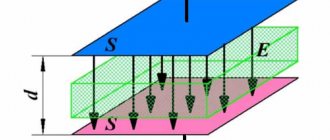
The first circuit consists of capacitance C1. This capacity is called geometric; it is characterized by the geometric characteristics of the insulation and its location relative to the ground. This capacitance is discharged instantly when the insulation is grounded after the test. That very same spark when applying grounding to the phase under test after the experiment.
The second circuit contains two elements - capacitance C2 and active resistance R2. This circuit simulates losses when AC voltage is applied to the insulation. R2 characterizes the structure and quality of the insulation. The more frayed the insulation, the lower the R2 value. Capacity C2 is called absorption capacity. This capacitance is charged, when a constant voltage is applied, not instantly, but in a time proportional to the product of R2 by C2. The better the dielectric properties of the insulation, the longer it will take the capacitance C2 to charge, because the value of R2 will be greater for healthy insulation. In general, this capacitance answers the question why, after a spark, it is necessary to keep the grounding on the test core for a couple of minutes. It discharges slowly and does not charge instantly.
The third branch consists of active resistance R3, which characterizes the insulation leakage current and losses. The current increases when the insulation is moistened and is proportional to the insulation area and inversely proportional to the insulation thickness. Here is an electrical model of insulation.
Safe operation of the megohmmeter
Any measurements should be made only with a working megohmmeter. The device must be tested in a laboratory where its own insulation and all components are checked. An increased voltage is used for testing, after which the megohmmeter is given permission to operate for a certain, limited period.
For verification purposes, the megohmmeter is sent to a metrology laboratory, where specialists determine its accuracy class. Passage of control measurements is confirmed by a stamp applied to the body of the device. During further operation, the safety and integrity of the mark must be maintained, especially the date and number of the specialist who carried out the verification. Otherwise, the device will automatically fall into the faulty category.
The correct application area also ensures safety when working with the megohmmeter. Before each measurement, the output voltage value is determined. The device is primarily used for insulation testing. For this purpose, extreme conditions are created for the area being tested, when not the rated voltage, but an overestimated voltage is supplied. The time period is also quite long. This contributes to the timely identification of possible defects and their prevention in subsequent operation.
Each circuit to be tested has its own characteristics that affect the safe operation of the megohmmeter. Therefore, before applying high voltage to the desired area, it is necessary to eliminate all malfunctions and breakdowns of the constituent elements. Modern equipment is literally saturated with semiconductors, capacitors, measuring and microprocessor instruments. They are not designed for the high voltage generated by the megohmmeter generator. Before testing, all such devices are bypassed or completely removed from the circuit. At the end of the measurements, the circuit is restored and brought into working condition.
The main thing here is the effect of surprise.. I have a device at work for an older person, it gives out about 500V to the touch, although it says 1kV, one range, no switches, a stupid handle and 3 ends
The name of this device is made up of three words: “mega”, denoting the dimension of the measurement value (one thousand thousand or 10 6), “ohm” - a unit of electrical resistance, “meter” - an abbreviation for measure. The technical purpose of the device immediately becomes clear: measuring electrical resistance in the megaohm range.
Often, experts in the Russian language correct this word, excluding the letter “a” from it, under the pretext that two vowels in a row are dissonant when pronounced. But this technique distorts the meaning inherent in the device in the same way as the slang of individual electricians - “vixen”.
The principle of measuring insulation resistance with a megohmmeter
The operation of the device is based on the famous Ohm's law for the circuit section I=U/R. To implement it, any modification has the following built in inside the case:
source of constant, calibrated voltage;
The design of the voltage generator can vary significantly and can be created on the basis of simple hand-held dynamos, as in older models, or by using power from a built-in or external source.
The output power of the generator, as well as the value of its voltage, can include several ranges or be performed with a single, fixed value.
Connecting wires are connected to the terminals of the device, the other end of which is connected to the circuit being measured. Alligator clips are usually used for these purposes.
An ammeter built into the electrical circuit measures the current flowing through the circuit. Taking into account the fact that the generator voltage is already known and calibrated, the scale of the measuring head is immediately calibrated in converted resistance units - megaohms or kiloohms.
This is what the scale of an old analog device of the M4100/5 series, proven by fifty years of operation, looks like. It allows you to take measurements at two scale limits:
If the megohmmeter is created using new digital signal processing technologies, then its display also displays the resistance, but in a more visual form.
How does a megaohmmeter work?
Let's consider this issue using the example of a simplified electrical circuit of an analog device.
When analyzing it, the following components are clearly identified:
DC generator;
a measuring head assembled on the basis of the principle of interaction of two frames (working and counteracting);
toggle switch for measurement limits, which allows you to switch various resistor chains to change the output voltage and operating mode of the head;
Read also: Do-it-yourself grounding device at the dacha
A fairly simple diagram does not contain any unnecessary elements. On the sealed, durable dielectric housing of such a device are placed:
handle for easy transportation;
a folding portable generator handle that must be rotated to generate voltage;
toggle switch lever for switching measurement modes;
output terminals for connecting the connecting wires of the circuit.
Almost all megaohmmeter designs have three output terminals, which are called:
The ground and line terminals are used for all insulation resistance measurements relative to the ground loop, and the shield terminal is designed to eliminate the influence of leakage currents when making measurements between two parallel conductors of a cable or other similar live parts.
To put it into operation, it is necessary to use one specially designed measuring wire with shielded ends. The device is always equipped with it at the factory. It has two terminals at one end, one of them is marked with the letter E. This terminal is connected to the corresponding terminal of the megohmmeter.
An example of connecting the measuring ends to the device is shown in the figure.
Here, instead of terminals “L” and “Z”, the indices “rx” and “-” are used. This is simply a new marking that replaces the old one on modern devices.
The picture shows that terminal “E” is used to connect to the screen or casing. They use it to carry out special precise measurements. Megaohmmeters that use power for the generator from built-in batteries or an external network. work on the same principles. Only they don’t have to turn the handle. To output voltage to the circuit under test, they hold the button pressed. Moreover, devices capable of producing several voltage combinations use not one, but two, three buttons or combinations thereof.
The internal structure of such megaohmmeters is much more complex. We do not consider it here, since this issue relates more to repair work and not to measurements.
The voltage that the megaohmmeter generator of various models produces can be one of the following values: 100, 250, 500, 700, 1000, 2500 volts. Moreover, some devices operate on one range, while others have several.
The output power of devices designed to test the insulation of industrial high-voltage equipment can be several times higher than the characteristics of models designed to work in household electrical wiring conditions. The dimensions of such devices will also differ.
For this reason, focusing on small structures that can be kept in a jacket pocket may not be justified in all cases.
What to pay attention to when working with a megaometer
Increased device voltage
The output power of the megohmmeter generator is quite enough to not only detect the appearance of microcracks in the insulation layer, but also cause serious electrical injury.
For this reason, safety regulations permit the use of the device only by trained and well-trained personnel authorized to work in live electrical installations. And this is at least the third group for TB.
During measurement, increased voltage of the device is present on the circuit under test, connecting wires and terminals. To protect against it, special probes are used, installed on measuring wires with a reinforced insulation surface.
At the ends of the probes, a restricted area is marked with safety rings. It should not be touched with exposed parts of the body. Otherwise, you may be exposed to voltage.
To manipulate the measuring probes, grasp the surface of the working area with your hands. During measurements, well-insulated alligator clips are used to connect to the circuit. The use of other wires and probes is prohibited.
There should be no people in the entire test area during the measurement. This is especially true when measuring the insulation resistance of long cables, the length of which can be several kilometers.
Induced voltage
The energy passing through the wires of power lines has a large magnetic field, which, changing according to a sinusoidal law, induces a secondary EMF and current I2 in all metal conductors. Its value on extended products can reach large values.
This factor must be taken into account for two reasons:
1. accuracy of measurement;
2. safety of working personnel.
The first reason is that when assembling a circuit for measuring insulation resistance, a current of unknown magnitude and direction will flow through the measuring organ of the megohmmeter, caused by the induction of electrical energy. Its value will be added to the meter reading from the calibrated generator voltage.
As a result, two unknown current values are summed up in an arbitrary manner and create an insoluble metrological problem. Measuring the resistance of electrical circuits under any voltage, and not just induced voltage, is therefore generally meaningless.
The second reason is that working under induced voltage can lead to electrical injuries and requires strict adherence to safety rules.
Residual charge
When the generator of the device supplies voltage to the network being measured, a potential difference is created between the electrical equipment bus or line wire and the ground circuit and a capacitance is formed that receives a charge.
After the megohmmeter circuit is broken by disconnecting the measuring wire, part of this potential is retained: the bus or wire has a capacitive charge. As soon as a person touches this area, he receives electrical injury from the discharge current through his body.
For this reason, it is necessary to take additional safety precautions and always use a portable grounding device with an insulated handle to safely remove capacitive voltage.
Before connecting a megohmmeter to a circuit whose insulation will be measured, it is always necessary to check that there is no voltage or residual charge on it. This is done with a tested indicator or a verified voltmeter of appropriate ratings.
After each measurement, the capacitive charge is removed by portable grounding using an insulating rod and other additional protective equipment.
Typically, you need to take a lot of measurements with a megohmmeter. For example, in order to draw a conclusion about the quality of the insulation of a ten-core control cable, it is necessary to check it against the ground and each core and between all the cores in turn. For each measurement, it is necessary to use a portable grounding connection.
For quick and safe work, one end of the grounding conductor is initially connected to the ground loop and left in this position until the work is completed.
The second end of the wire is attached to an insulating rod and with its help, grounding is applied each time to remove the residual charge.
Basic rules for the safe use of a megohmmeter
Verification and testing
Any work in electrical installations may only be carried out with working electrical devices.
In relation to a megohmmeter, this means that it must simultaneously meet two requirements and be:
Testing means testing the resistance of its own insulation and all components in an electrical testing laboratory with increased voltage. Based on its implementation, the owner of the device is issued a certificate authorizing the operation of the megohmmeter for a certain, limited period.
Verification is carried out by metrology laboratory specialists in order to determine the accuracy class of the device and apply a stamp on its body indicating that it has passed control measurements. The owner is obliged to take measures to ensure the safety of the applied stamp with the date and number of the verifier. If it disappears, the device is automatically considered faulty.
Types of jobs
The megohmmeter is selected for each measurement primarily based on the output voltage. It can perform two different types of checks:
1. insulation tests;
2. measurement of the resistance of the dielectric layer.
The first method involves creating an extreme case for the test area. For this purpose, it is supplied not with the rated voltage, but with an overestimated voltage provided for in the technical documentation. The test time is also chosen to be quite long. This allows you to timely identify all insulation defects and eliminate their manifestation during operation.
Read also: Nut size for grinder
The second method uses a more gentle mode. The voltage for it is selected to a lower value, and the measurement time is determined by the duration of the end of the capacitive charge of the measuring section. For electrodynamic devices, it does not exceed a minute (that’s how long you need to turn the knob at a speed of 120÷140 rpm), and for electronic devices - about 30 seconds (keep the button pressed).
For example, measuring the insulation resistance of a particular electrical circuit must be done with a megohmmeter that produces 500 volts at the output. Then to test it you will need a 1000 V device.
Insulation measurements are carried out by electrical personnel of various professions, and the testing function is provided only to specialists from the insulation service laboratory. Quite often, the capabilities of a megohmmeter for these purposes are not enough for them, and they include in their work additional installations and sources of extraneous voltage that have higher powers and measuring capabilities.
Knowledge of the features of the circuit being tested
Before applying high voltage to the area being measured, it is necessary to take measures to prevent breakdowns and malfunctions of its components. Modern electrical equipment uses many semiconductor elements, various capacitors, measuring and microprocessor devices. They are not designed for the operating conditions created by the megohmmeter generator voltage.
All such devices must be protected. To do this, they are removed from the circuit or shunted in a certain way.
After the measurements are completed, the entire circuit must be restored and brought into working condition.
How to measure insulation resistance
It is recommended to divide the technological process into three main stages:
1. preparatory part;
2. taking measurements;
3. final stage.
During preparation you must:
decide on organizational arrangements, determine the performers and their qualifications;
familiarize yourself with the electrical installation diagram and take measures to prevent damage to its components;
prepare protective equipment and working measuring instruments;
remove a section of electrical equipment from operation.
Before you start working with a megohmmeter, it is important to make sure that it is in good working order. To do this, connect the measuring wires to its terminals and short-circuit their output ends to each other. Then voltage is applied from the generator and the reading is monitored.
A working device should measure the shorted circuit and show the result - 0. Then the ends are disconnected, moved to the sides and the measurement is repeated. The scale should display another value - ∞. This is the insulation resistance of the air gap between the open ends of the megohmmeter.
Based on these two readings, a conclusion is made about the technical serviceability of the device, the integrity of the connecting wires and readiness for operation.
Performing a direct measurement of the insulation resistance of one wire comes down to a strict sequence of actions:
1. connecting portable grounding to the earth circuit;
2. checking and ensuring that there is no voltage in the test area;
3. installation of portable grounding while connecting the device;
4. assembly of the megohmmeter measurement circuit;
5. removal of portable grounding;
6. applying a calibrated voltage to the circuit until the capacitive charge is equalized and fixing the reading, followed by removing the voltage;
7. application of portable grounding to remove residual charge;
8. disconnecting the connecting wire of the device from the circuit;
9. removal of portable grounding.
Resistance measurements are performed at the highest MΩ limit. When its value becomes insufficient, they switch to a more accurate range.
In all subsequent measurement chains, this sequence must be strictly observed. Some models of megaohmmeters have an intermittent mode, when voltage is supplied for 1 minute and after that a two-minute pause must be maintained. This limitation cannot be ignored.
Electrodynamic devices with a dial indicator are designed for measurements with a horizontal orientation of the body. If this requirement is violated, an additional error occurs. Most digital modern megohmmeters do not have this drawback.
All measurements are recorded in a pre-prepared protocol and signed by responsible employees. It displays the operating conditions and serial numbers of the devices used.
The final stage
All disassembled chains must be restored. Shunts and short circuits installed for safe measurements are removed.
The circuit is made ready to supply operating voltage for commissioning.
At the final stage, the documentation of the insulation resistance measurement results is completed.
Attention! The material in the article is advisory in nature and is intended for informational purposes for novice specialists. A more precise interpretation of the rules for using megaohmmeters is set out in the relevant technical documentation and current regulations. Knowing and meeting their requirements is the professional responsibility of every electrician.
To assess the performance of a cable or wiring, it is necessary to measure the insulation resistance. There is a special device for this - a megohmmeter. It applies high voltage to the circuit being measured, measures the current flowing through it, and displays the results on a screen or scale. We’ll look at how to use a megohmmeter in this article.
Insulation resistance: how to measure correctly
Before measuring resistance, you need to carefully study the electrical installation diagram, prepare protective equipment and the device itself is in good condition. The area being tested must be taken out of operation in advance.
Checking the serviceability of the megohmmeter is as follows. The test leads are shorted together. After this, voltage is supplied to them from the generator. If the device is working properly, the measurement results of the shorted circuit are zero. Next, the ends of the wires are disconnected, moved to the sides, after which a repeat measurement is made. Normally, the scale displays an infinity symbol, indicating the insulation resistance in the air gap between the measuring ends.
Direct measurement of insulation resistance is performed in a strictly defined sequence. First of all, the portable ground must be connected to the circuit. There should be no voltage in the area being tested. Next, the measuring circuit of the device is assembled, and the portable grounding is removed.
A calibrated voltage is applied to the circuit until the capacitive charge is equalized. Next, the countdown is recorded, after which the voltage is removed. To remove the residual charge, a portable grounding is applied. At the end of the measurements, the connecting wire is disconnected from the circuit, and the grounding is removed.
To measure insulation resistance with a megohmmeter, the highest MΩ limit is used. If this value is not enough, you need to use a more accurate range. All further chains of measurements must be performed in the same sequence. Some megaohmmeter designs can operate in intermittent mode. In this case, voltage is applied for one minute, after which there is a pause for two minutes.
If there is a dial indicator in the measuring instruments, the horizontal orientation of the body is used for all measurements. Violation of this requirement leads to additional errors. Modern digital megohmmeters can operate in any position.
Procedure for checking cable insulation resistance with a megohmmeter
You come to the site and see, for example, the following picture.
Before directly checking the insulation resistance, you must make sure that:
- The cable cores are ringed and marked (read about ringing here)
- on the cable cores where we will supply voltage there is no dirt, scale, or paint (there is no such thing on the cable core, but it may be on the grounding, which is painted, or it may be covered with a layer of rust, then you need to scrape it off with a screwdriver or knife)
- at the other end of the cable no one is working and the cable is disconnected from the load and the power source (it is not worth applying voltage to the installer, who can cut the cable from the other side, or measuring the Rx of the cable with the load, it is also worth making sure that we do not apply high voltage to the secondary circuits and elements that can become unusable at 2500V, so sometimes they are simply switched to 500V)
- the cable is de-energized and measures are in place to prevent accidental supply of voltage to the cable under test (locks, posters, cells removed)
- if the vigilante test (measurement of insulation resistance) is combined with high-voltage tests, then you need to make sure that there is a person at the second end of the cable (the second end is opposite from the test site) or the room is locked and fenced with posters posted
- The megohmmeter is in good condition and suitable for use (verification mark on the body and the ends of the device are tested)
- you have the right and qualifications to work with a megohmmeter and perform this type of work (group 3 on electrical safety and an unexpired test of special knowledge, plus a medical examination)
- the megohmmeter wires must have high insulation (here you can also do the following: connect the two megohmmeter wires and apply voltage - the value should be zero, since there is no insulation between the wires, and if separated, then infinity - since the air resistance is high)
Once the above points have clearly been implemented, you can get down to business. Let's play together!