General information
In order to understand what the inductance of the coil depends on, it is necessary to study in detail all the information about this physical quantity. The first step is to consider the accepted international designation of the parameter, its purpose, characteristics and units of measurement.
The very concept of inductance was proposed by the famous English physicist Oliver Heaviside, who studied it. This scientist gave the world other well-known terms - electrical conductivity, magnetic permeability and resistance, as well as EMF (electromotive force).
The first letter of the surname of another famous physicist, Emilia Lenza, was taken as a designation for inductance in formulas and when carrying out calculations. Today, the symbol L continues to be used when referring to this parameter.
The outstanding American physicist Joseph Henry was the first to discover the phenomenon of inductance. In his honor, physicists named the unit of measurement in the international SI, which is most often used in calculations. In other systems (Gaussian and SGS), inductance is measured in centimeters. To simplify the calculations, a relationship was adopted in which 1 cm equals 1 nanohenry. The very rarely used SGSE system leaves the self-induction coefficient without any units of measurement or uses the stathenry value. It depends on several parameters and is approximately equal to 89875520000 henry.
Among the main properties of inductance are:
- The parameter value can never be less than zero.
- The indicator depends only on the magnetic properties of the coil core, as well as on the geometric dimensions of the circuit.
Calculation methods
There are several basic ways to determine the inductance of a coil. All formulas that will be used in the calculations can be easily found in reference books or on the Internet. The whole calculation process is quite simple and will not be difficult for people with basic mathematical and physical knowledge.
Through current
This calculation is considered the simplest way to determine the inductance of a coil. The formula through current follows from the term itself. What is the inductance of the coil can be determined by the formula: L=Ф/I, where:
- L - circuit inductance (in Henry);
- F is the magnitude of the magnetic flux, measured in webers;
- I is the current strength in the coil (in amperes).
This formula is only suitable for a single-turn circuit. If the coil consists of several turns, then instead of the magnetic flux value, the total flux (total value) is used. When the same magnetic flux passes through all the turns, then to determine the total value it is enough to multiply the value of one of them by the total number.
Finite Length Solenoid
The solenoid is a thin long coil, where the thickness of the winding is significantly less than the diameter. In this case, calculations are carried out using the same formula as through current strength, only the magnitude of the magnetic flux will be determined as follows: Ф=µ0NS/l, where:
- µ0 is the magnetic permeability of the medium, determined from lookup tables (for air, which is taken by default in most calculations, it is equal to 0.00000126 henry/meter);
- N is the number of turns in the coil;
- S is the cross-sectional area of the coil, measured in square meters;
- l is the length of the solenoid in meters.
The self-induction coefficient of the solenoid can also be calculated based on the method for determining the energy of the magnetic flux of the field. This is a simpler option, but it requires some quantities. The formula for finding inductance is L=2W/I 2, where:
- W is the magnetic flux energy, measured in joules;
- I is the current strength in amperes.
Toroidal core coil
In most cases, a toroidal coil is wound on a core made of a material with high magnetic permeability. In this case, to calculate the inductance, you can use the formula for a straight solenoid of infinite length. It has the following form: L=N µ0 µS/2 πr, where:
- N is the number of coil turns;
- µ—relative magnetic permeability;
- µ0—magnetic constant;
- S is the cross-sectional area of the core;
- π is a mathematical constant equal to 3.14;
- r is the average radius of the torus.
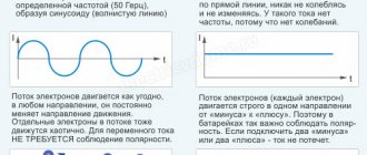
Long conductor
Most of these quasi-linear conductors have a circular cross-section. In this case, the value of the self-induction coefficient will be determined by the standard formula for approximate calculations: L= µ0l (µelnl/r+ µi/4)/2 π. The following notations are used here:
- l is the length of the conductor in meters;
- r is the radius of the wire cross-section, measured in meters;
- µ0—magnetic constant;
- µi is the relative magnetic permeability characteristic of the material from which the conductor is made;
- µe is the relative magnetic permeability of the external environment (most often the value for vacuum is taken to be 1);
- π—pi number;
- ln is the notation for logarithm.
Measurement options
The inductance of a coil in physics is determined by performing calculations. However, this value can not only be calculated, but also measured. This is done using a direct or indirect method.
Direct method
To measure the inductance of a coil using this method, it is necessary to use special bridge or direct-indicating devices. With their help, you can obtain the most accurate data that will help you select the required coil for the circuit.
The procedure for carrying out measurements includes the following steps :
- A coil is connected to the direct indicating device.
- After this, the measurement ranges are gradually changed. This is done until the result obtained is approximately in the middle of the interval.
- The result obtained is recorded and calculated taking into account the division value of the device, as well as the coefficient corresponding to the position of the switch.
Measuring instruments
If you have measuring instruments at hand, then using them it is quite easy to find the current strength. You just need to follow the measurement rules and not forget about the safety rules.
Ammeter
When using instruments for measuring amperage, you should remember that they are connected in series in the circuit. The internal resistance of the ammeter is very small, so the device is easily damaged if measurements are taken outside the values for which it is designed.
Multilayer inductor calculator
In practice, situations often occur when, when an inductor fails, it is necessary to restore it - wind a new wire to replace the old one. In this case, you already know the geometric parameters of the coil, but you need to find out how many turns, layers, their thickness and the length of the wire required for this. It is worth noting that when winding, the turns should lie closely without a gap.
To calculate the inductance of a multilayer coil, the following formula is used:
- d – the sum of the frame diameter and the winding thickness on one side only;
- n – number of turns;
- g – thickness of the wound wire;
- h – height of the wound wire;
From this formula, knowing the inductance value, we can derive the winding thickness:
To determine the number of turns, you must use the formula:
- dpr – wire diameter
- h – coil height;
- g – winding thickness.
Calculation of the number of turns
The length of one turn can be determined as follows:
Where π is a constant, and dvit_ is the diameter of the coil.
Then, knowing the total number of turns and assuming that d is the average diameter for all turns, the length of the entire wire will be determined by the formula:
Through the resistance of a wire, you can determine its diameter, for which you will need to express the resistance through the geometric parameters of the device.
where ρ is the resistivity of the metal from which the conductor is made, and S is the area of the conductor, which is determined by the formula:
Substituting the area and length of the wire, we obtain the following expression for determining the resistance:
From the resistance value, you can derive a formula for determining the wire diameter by first substituting the formula for calculating the number of turns:
After obtaining the wire diameter, you can determine the number of turns, which is substituted with the rest of the data in the first formula for calculating inductance.
The number of layers can be determined by dividing the winding thickness by the diameter of the wire:
Using the above calculations, you can determine all the parameters of a multilayer inductor, which will help you make a device with the desired parameters. Also, to make calculations easier, you can use our online calculator below.
Share on social networks
Application of inductors
Inductors are widely used in analog and signal processing circuits. They combine with capacitors and other radio components to form special circuits that can amplify or filter signals of a specific frequency.
Inductors have a wide range of applications ranging from large inductors such as power supply chokes that, in combination with filter capacitors, eliminate residual noise and other oscillations in the power supply output, to as small inductors as those found inside integrated circuits.
Two (or more) inductors, which are connected by a single magnetic flux, form a transformer, which is the main component of circuits operating with an electrical power supply network. Transformer efficiency increases with increasing voltage frequency.
For this reason, aircraft use AC voltage with a frequency of 400 hertz instead of the usual 50 or 60 hertz, which in turn allows for significant savings in the mass of transformers used in the aircraft power supply.
Inductors are also used as energy storage devices in switching voltage stabilizers, in high-voltage electrical power transmission systems to deliberately reduce system voltage or limit short-circuit current.
Source
Comments and reviews (7)
Vadim
Why do all inductance calculation calculators not take into account the magnetic permeability of different types of cores without it? The number of turns being wound is not clear regarding what, air ferrite or iron.
Novel
Winding length (meaning) - length of the coil frame
Valery
I used this calculator to calculate 0.5 mH with a 1 mm wire on a frame with a diameter of 23 mm, a length of 30 mm, winding in bulk ... the calculator produced 178 turns, wound 180, the actual measured inductance was 550 μH
Calculation of the inductor
Online calculation of a multilayer coil. The calculator calculates using an algorithm using Maxwell's elliptic integrals. An inductor is a helical, helical or helical coil made of a coiled insulated conductor, which has significant inductance with a relatively small capacitance and low active resistance. The inductance of the coil depends on its geometric dimensions, the number of turns and the method of winding the coil. The larger the diameter, winding length and number of turns of the coil, the greater its inductance.
see also
A very strange result is obtained. At 3.4 mg d20 L35 wire 1/1.2, one layer is obtained and the wire consumption is less than one meter. Like this??
Try changing microhenry to millihenry
Maybe they confused milihenry and microhenry?
Here the calculation is clearly without a core, otherwise there would be other data, for example, the permeability of the core.
What about the core? With or without a core?
Ingvar, why do you really need the letters NNNN? Length! I give it.
The winding length is the length of the coil from the starting point of the winding to the end of the calculated conductor (meters), the length of the conductor is calculated from the resistance you need. For example, for a magnetic system you need at least 1 mm and no more than 3 (2 layers of winding), but due to the length of the conductor you get 6 mm, you will have to increase the number of layers (up to 4) and make the coil thicker, but shorter.
The main thing is inductance and resistance. The longer the wire, the greater its resistance!
The length of the winding does not affect the results in any way. Is this how it should be?
Source
Ideal and real inductors
For ideal inductors, when connected to a sinusoidal voltage source, the current lags in phase with the voltage by p/2, inductive reactance RL
= w
L
, where
L
is inductance (self-inductance coefficient).
As in the case of capacitors, in real coils the phase shift between current and voltage is slightly less than p/2 - by the amount d
, due to energy losses in the coil when alternating current flows through it - mainly due to heating of the winding wire.
The value is called the quality factor of the coil
. For a series equivalent circuit, for a parallel circuit.
In some cases, especially at high frequencies, more complex equivalent circuits are used, which additionally take into account the inductance of the capacitor leads and the interturn capacitance of the coils.
Low Frequency AC Measuring Bridges
Capacitances and dielectric loss tangents of capacitors, inductance and quality factor of coils can be measured using various bridge circuits. Consider the diagram of a four-arm bridge:
Rice. 3.
Its arms can contain active resistances, capacitances and inductances and are characterized by impedances (complex resistances). WITH
The circuit is powered by alternating sinusoidal voltage. The condition for the balance of the AC bridge (i.e., the current of the AND indicator being equal to zero) is similar to the condition for the balance of the DC bridge (see work No. 10):
| (5) |
The choice of a specific bridge circuit depends on what equivalent circuit we want to represent the capacitor or inductor under study.
For a series equivalent circuit of a capacitor, it is convenient to use a bridge of the following type: Fig. 4.
Here R0
- graduated (equipped with a scale) variable resistor, C
0
- graduated capacitor with minimal losses (with an air dielectric). Condition (5) for this scheme will be written as:
| or | (6) |
For two complex numbers to be equal, it is necessary that their real and imaginary parts be equal, respectively. Therefore, equality (6) splits into two:
| R X R 2 = R0R 1 and | (7) |
From these expressions we obtain two bridge balance conditions that must be met simultaneously:
| (8) |
| (9) |
Model inductors are almost never used in AC bridges, because
it is difficult to make a coil with very low losses. To measure the parameters of coils in a series equivalent circuit, a bridge of the following type is usually used: Fig. 5.
Condition (5) for this scheme will be written as:
| (10) |
whence, after simplifications and separation of the real and imaginary parts, we obtain:
| (11) |
And
| (12) |
Balancing of the considered bridges is carried out by alternately changing the values of C0
and
R0
.
To expand the measurement limits, the values of R
1/
R
2 or
R
1
R
2 are sometimes changed stepwise.
Calculation of the inductor
When building electronic devices, you often have to deal with an inductive circuit element. When only the inductance value L is indicated in the drawing, you have to calculate the inductor yourself. There are many programs on the Internet that allow you to calculate the inductance of coils online using a special calculator. Knowing how the element is structured, you can manually perform all the calculations.
Inductor design
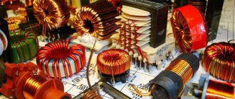
An inductor is a winding of conductive material, usually copper wire, wound around either an iron-containing core or no core at all.
The use of materials with high magnetic permeability, higher than air, as a core helps to retain the magnetic field near the coil, thereby increasing its inductance. Inductive coils come in different shapes and sizes.
Most are made by winding enameled copper wire over a ferrite core.
Some inductive coils have an adjustable core that allows the inductance to vary.
Miniature coils can be etched directly onto the PCB in a spiral pattern. Low-value inductors can be located in microcircuits using the same technological processes used to create transistors.
What is an inductor
This element is also called a choke. This is an insulated wire rolled into a spiral. Such a spiral is characterized by large inductive and small capacitive parameters.
Important! The inductor prevents the flow of alternating current because it has significant inertia. It prevents any change in the current passing through the turns. It makes no difference whether it increases or decreases.
In this regard, these elements are used in electrical engineering to implement:
- current limiting;
- weakening of beats;
- interference suppression;
- magnetic field formation;
- manufacturing motion sensors.
The choke is part of the oscillatory circuit system in resonance circuits and is used in delay lines.
Magnetic field energy of an inductor
Electric current contributes to the accumulation of energy in the magnetic field of the coil. If the electricity supply is turned off, the accumulated energy will be returned to the electrical circuit. In this case, the voltage value in the coil circuit increases many times. The amount of stored energy in the magnetic field is approximately equal to the amount of work that must be obtained to ensure the appearance of the required current in the circuit. The value of the energy stored by the inductor can be calculated using the formula.
What parameters does the coil have?
Its design depends on where the inductive element will be used and at what frequency it will operate. There are general parameters:
- L – inductance;
- R sweat – loss resistance;
- Q – quality factor;
- its resonance and parasitic capacitance;
- coefficients TKI and TKD.
Inductance (self-inductance coefficient) L is the main electrical characteristic of the element, which shows the amount of energy accumulated by the inductor when current flows. The greater the inductance, the higher the energy in the coil. Unit of measurement L – 1 Hn.
Energy conversion in an inductor
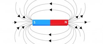
From the 11th grade physics course we know that an electric current passing through an inductor creates a magnetic field. As a result of self-induction, a change in this magnetic field induces an induced emf in the same coil, which, according to Lenz's rule, is directed so as to counteract the cause that caused it.
Rice. 1. Lenz's rule.
An inductor can be said to “resist” any changes in current through it, and the electric field must expend energy to make such changes (both to increase the current and to decrease it).
Where does this energy go?
Since there are no “energy receivers” in the inductor, we can conclude that the energy of the electric field is spent on “accelerating” the electrons in the coil and creating a magnetic field in it. If the electric field is removed, the electrons will not stop immediately either, but due to the energy of the magnetic field they will continue to move for some time, returning the energy to the conductor.
Thus, the inductor has the ability to store energy in a magnetic field. When the current is turned on, its energy is spent on creating a magnetic field, and when turned off, the energy of the current’s magnetic field is returned to the conductor.
We emphasize that the energy of the magnetic field has a significantly different nature than the internal energy of the conductor, which is expressed by the Joule-Lenz law. The energy of the magnetic field of a current is the kinetic energy of charges moving in an orderly manner along it. The internal energy of a conductor is the energy of the chaotic movement of the molecules of the conductor itself. Magnetic field energy can be easily obtained by reducing the current in a conductor. In this case, the magnetic field of the coil, decreasing, will do positive work. The second law of thermodynamics prohibits obtaining internal field energy without additional energy expenditure.
Rice. 2. Second law of thermodynamics.
Coil design
Inductive elements differ in design:
- type of winding: helical, screw; ring;
- number of layers: single-layer or multi-layer;
- type of insulated wire: single-core, stranded;
- the presence of a frame: framed or frameless (with a small number of turns of thick wire);
- frame geometry: rectangular, square, toroidal;
- the presence of a core: ferrite, carbonyl iron, electrical steel, permalloy (soft magnetic alloy), metal (brass);
- core geometry: rod (open), ring-shaped or w-shaped (closed);
- the ability to change L in narrow intervals (movement of the core relative to the winding).
There are flat coils that are printed and installed on the boards of digital devices.
For your information. Wire winding can be either ordinary (turn to turn) or in bulk. The latter method of laying the wire reduces parasitic capacitance.
Replacement circuit for an inductor of a small nominal value with a larger one.
Online calculator for calculating the equivalent LC circuit.It would seem, what problems can be associated with small values of coil inductance? On the contrary - fewer turns, thicker wire... Sit and rejoice, if you don’t know how to rejoice, just sit. And, indeed, there is something to be happy about: these are acceptable weight and size characteristics, low losses, and high quality factor of such winding products. But no, something makes my amateur radio darling itch when she encounters images of coils of nano-Henry denominations. Moreover, if there are no special problems with inductance values of 25 - 35 nH (this is 2-3 turns of a millimeter wire wound on a 5 mm mandrel), then values less than 10 nH sometimes cause confusion and a feeling of bewilderment on the face of a young developer. Experienced microwave operators, of course, will laugh at this formulation of the problem; they know very well that such coils can be easily and naturally implemented on strip lines. However, for us, simple boys, as well as mysterious girls who are inaccessible to understanding and logical analysis, an equivalent circuit for replacing a low-value coil with a product that can be clearly wound will be very useful. There is no need to invent anything here; this scheme is known and is shown in Fig. 1. Fig.1
Since in a series circuit the total phase shift between the voltages on the coil and on the capacitor is 180°, the equality of the characteristic resistances of both circuits will look like this: XL = XL1 - XC1;
Having made the necessary transformations, we obtain a formula for calculating the capacitance of capacitor C1 for the required value of inductance L1: C1 = 1/[(2πF)2×(L1 - L)] ;
Let's spice up the resulting formula with a calculator.
CALCULATION OF ELEMENTS OF AN INDUCTANCE COIL SUBSTITUTION CIRCUIT.
The Buddha urged his disciples not to take anyone's word for it (not even his), and before accepting someone's advice, carefully find out whether it corresponds to reality. Let's do the same.
Fig.2
First, let's look at the circuit diagram for matching the output stage of the transmitter with the antenna (Fig. 2). The calculation of the elements was made for a frequency of 145 MHz on the page link to the page. Now let's see how the transmission coefficient and frequency response of the circuit behave when we replace the inductor L1 with a nominal value of 7 nH with the circuit shown in Fig. 1.
Fig.3
The top diagram of Fig. 3 shows the frequency response of the circuit with the original L1 = 7 nH, below - when replacing L1 with a chain consisting of: 20 nH and 91 pF, even lower - when replacing it with a chain: 40 nH and 36 pF. Well, what can I say? There is a slight decrease in the transmission coefficient and a significant narrowing of the bandwidth. Moreover, the greater the value of the new coil in relation to the original one, the stronger these effects appear.
Now let's do the same with the interstage matching circuit calculated on page link to page.
Fig.4
Fig.5
Inductors in this case were used with ratings of 6.5, 20 and 40 nH. The trend observed is the same as in the previous case, but less pronounced. Yes, this is understandable - with such a low load resistance, the quality factor of the loaded circuit is much lower.
What conclusions can be drawn by observing the electron flows described above in the modified coils? In principle, such a scheme for replacing small inductances with coils of higher ratings has the right to life. Despite some deterioration in transfer characteristics and a narrowing of the bandwidth of matching devices, the ability to manufacture a winding product with predictable parameters may be a decisive factor for someone when choosing this circuit solution. Here it is important not to be too zealous and not to chase significant values, but to limit the inductance increase factor to 3-4 times.
Calculation of coil parameters
We have to consider different options when making calculations. The calculation of inductance depends on the initial data and the specified final parameters.
Calculation of L depending on the given design
If the initial parameters are: w , D frame and the length of the wound wire, then the formula for calculation is:
L = 0.01*D*w2/(l/D) + 0.46,
Where:
- D – frame diameter, cm;
- w – number of turns;
- l – winding length, cm;
- L – inductance, µH.
Substituting numerical values into the formula, the value of L is obtained.
Calculation of the number of turns by inductance
Knowing D frame and L , calculate the number of turns in the coil, the formula looks like:
Where:
- L – inductance, µH;
- D – frame diameter, mm.
If the length of the conductor wound in a row and its diameter are taken as the initial parameters, then the number of turns is found using the formula:
Where:
- l – winding length, mm;
- d – wire diameter, mm.
Wire diameter measurements are carried out with a ruler or caliper.
Calculation of inductance of a straight wire
When planning to find L of a round straight conductor, we turn to the approximate formula:
L = (μ0/2π)*l*( μe*ln(l/r) + 1/4* μi,
Where:
- μ0 – magnetic constant;
- μe – relative magnetic permeability (RMP) of the medium (for vacuum – 1);
- μi – conductor OMF;
- l – wire length;
- r is the radius of the wire.
The formula is valid for a long conductor.
Calculation of single-layer winding
Single-layer chokes without a core can be easily and quickly calculated using an online calculator, in the window of which you can enter all known characteristics, and the program will display the value L.
Calculations are also carried out manually, using a mathematical expression. It looks like:
L = D2*n2/45D + 100*l,
Where:
- D – coil diameter, cm;
- l – length of the wound wire, cm;
- n – number of turns.
The formula is suitable for calculating L chokes without ferrite cores.
Core choke
If there is a core, its size and shape should be taken into account. In the case of identical coils, the inductance is greater in the one located on the core.
Multilayer winding
Features of the calculation with this method of winding wire are that you need to take into account its thickness. The formula for a coreless choke is:
Where:
- Dk – total diameter (diameter of frame and winding);
- t – layer thickness;
- l is the length of the wound wire.
All values are substituted in mm, the value of L is in µH.
Equivalent circuit of a real inductor
Each inductor can be represented as an equivalent circuit.
This scheme consists of elements:
- Rw – resistance of the winding with leads;
- L – inductance;
- Cw – parasitic capacitance;
- Rl – loss resistance.
When manufacturing an inductive element, they strive to reduce the amount of loss resistance and parasitic capacitance. When the coil operates at a low frequency, the resistance of its winding Rw is taken into account. Large currents operate at such frequencies.
A correctly calculated inductor will have a high quality factor (180-300) and stable operation under the influence of external conditions (temperature and humidity). Knowing the methods of various winding and pitch manipulation, you can reduce the influence of parasitic factors.
EQUIVALENT DIAGRAM OF AN INDUCTANCE COIL. THE CONCEPT OF QUALITY.
Inductance usually makes up 7-10% of the total number of elements of electronic devices. Inductance is divided into 2 groups according to the type of core: - magnetic, - non-magnetic (air). Magnetic cores: - closed, - open. Real inductances are not pure inductances, because the wire on which it is wound has a series resistance R, and there is a distributed interturn capacitance between the turns of the winding. One of the characteristics of inductors is their sensitivity to stray magnetic fields and the ability to generate electric fields. Sources of interference are inductor coils with an air and open magnetic core, since F from them extends beyond the coil to considerable distances. The inductance on a closed magnetic core creates a much smaller magnetic leakage field and almost all of F remains inside the magnetic core. Magnetic core coils are more sensitive to magnetic fields than air core coils. At low frequency, the equivalent circuit of an inductor is:
The coil resistance increases with frequency due to skin effect and proximity effect. Therefore, the quality factor of the coil Q
not proportional to its frequency. At high frequencies, the capacitances between the turns cannot be neglected. Due to interturn capacitances, at high frequencies the equivalent and reactance of the coil can become capacitive.
REAL CONDUCTOR PARAMETERS
To evaluate the noise and transient characteristics of electrical circuits, it is necessary to take into account the actual parameters of the conductors.
One of the most important parameters of a conductor is inductance. Even at low frequencies, a conductor can have an inductive reactance that exceeds its active reactance. The inductance value of a conductor decreases as it approaches the grounding surface, and vice versa, as the conductor moves away from the grounding surface, its inductance increases.
The second important characteristic is resistance. The choice of conductor diameter is determined mainly by the maximum permissible voltage drop across it. At high frequencies, it should be borne in mind that, due to the skin effect, the resistance of the conductor increases. The skin effect causes a state of a conductor in which the current is concentrated near the surface of the conductor, which is caused by the presence of magnetic fields created by the current flowing in the conductor. As the frequency increases, the current concentrates closer to the surface. This reduces the effective cross-section through which current flows and thereby increases the effective resistance value.
The resistance of a conductor to alternating current can be reduced by changing the cross-sectional shape of the conductor. A conductor with a rectangular cross-section has less resistance to alternating current than a conductor with a round cross-section, since its surface area is larger per unit cross-sectional area.
You can also note the temperature coefficient of electrical resistance, which characterizes the dependence of electrical resistance on the temperature of the conductor. For most metals, the temperature coefficient of resistance is positive: their resistance increases with increasing temperature. But for semiconductors without impurities it is negative.