Unbranched electrical circuit
An unbranched electrical circuit can be represented by an equivalent RLC
circuit (Fig. 3.20).
With sinusoidal voltage
and voltages on the elements
are also sinusoidal, and uL
and
uC
are always in antiphase.
For instantaneous stress values, Kirchhoff’s second law is satisfied:
which can be represented in complex form
The nature of the complex resistance of the circuit
varies depending on the ratio of reactive xL
and
xC
components.
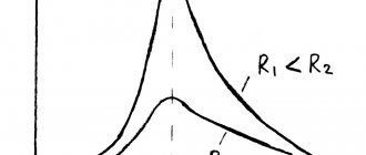
When ( ), the resistance of the circuit is inductive . Its argument is equal to the phase shift angle j
between current and applied voltage, positive (Fig. 3.21).
At ( ) the complex resistance of the circuit Z
has
a capacitive character , and its argument, equal to the phase shift angle, is negative: (Fig. 3.22).
At ( ) circuit resistance Z
has
an active character , as well.
For an unbranched chain, Ohm's law is valid:
The phase shifts between current and voltage in different sections of the circuit are different, their relationships are explained by vector diagrams for an active-inductive load (Fig. 3.23), for an active-capacitive load (Fig. 3.24, a
) and for active load (Fig. 3.24,
b
).
When constructing diagrams, the initial phase of the current is assumed to be zero, and the phase shift angle is plotted from the current vector counterclockwise.
From the diagrams it follows that the input voltage has active and reactive components. The vector of the active component is a projection of the vector onto the current vector and coincides with it in phase. The reactive component vector is a projection of the input voltage vector onto a direction orthogonal to the current vector and forms a phase shift π/2
.
With an inductive load, the reactive voltage leads by π/2
, with a capacitive load it lags behind by
π/2
.
If the capacitive and inductive reactances are equal, the reactive component of the circuit resistance is , the nature of the load is active, and the total voltage and current are in phase.
Circuit with series connection of elements R
,
L
,
C
can be represented by one of three equivalent equivalent circuits:
Serial connection of active R
and inductive
L
elements ( ) (see Fig. 3.23);
Serial connection of active R
and capacitive
C
elements ( ) (see Fig. 3.24,
a
);
active element R
( ) (see Fig. 3.24,
b
).
Phase angle j
= arctg
(x/R)
between the voltage applied to the circuit and the current is determined by the ratio of the reactive
x
and active
R
components of the circuit resistance, and not by the properties of the power source.
Source
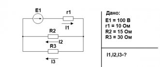
Unbranched and branched electrical circuits. Figure 2 - Branched chain
Figure 2 - Branched chain
Electrical circuits are divided into unbranched and branched. Figure 1 shows a diagram of the simplest unbranched chain. The same current flows in all its elements. The simplest branched chain is shown in Figure 2. It has three branches and two nodes. Each branch has its own current flowing. A branch can be defined as a section of a circuit formed by elements connected in series (through which the same current flows) and contained between two nodes. In turn, a node is a point in a chain at which at least three branches converge. If there is a dot at the intersection of two lines on the electrical diagram (Figure 2), then at this place there is an electrical connection between the two lines, otherwise there is not. A node at which two branches converge, one of which is a continuation of the other, is called a removable or degenerate node
[edit] Linear and nonlinear electrical circuits
A linear electrical circuit is a circuit in which all components are linear. Linear components include dependent and independent idealized current and voltage sources, resistors (subject to Ohm's law), and any other components described by linear differential equations, most famously electrical capacitors and inductances. If a circuit contains components other than those listed, then it is called nonlinear.
A representation of an electrical circuit using symbols is called an electrical diagram. The function of the dependence of the current flowing through a two-pole component on the voltage across this component is called the current-voltage characteristic (I-V characteristic). The current-voltage characteristics are often depicted graphically in Cartesian coordinates. In this case, voltage is usually plotted along the abscissa axis on the graph, and current is plotted along the ordinate axis.
In particular, ohmic resistors, the current-voltage characteristics of which are described by a linear function and are straight lines on the current-voltage characteristics graph, are called linear.
Examples of linear (usually to a very good approximation) circuits are circuits containing only resistors, capacitors and inductors without ferromagnetic cores.
Some nonlinear circuits can be approximately described as linear if the change in current or voltage increments across the component is small, and the nonlinear I-V characteristic of such a component is replaced by a linear one (tangent to the I-V characteristic at the operating point). This approach is called "linearization". In this case, a powerful mathematical apparatus for analyzing linear circuits can be applied to the circuit. Examples of such nonlinear circuits analyzed as linear include almost any electronic device operating in linear mode and containing nonlinear active and passive components (amplifiers, generators, etc.).
5.Resistive element, inductance, capacitance. Definition and designation on electrical diagrams. What energy is generated and how it is located.
An idealized two-pole element is called resistive, for which the relationship between voltage and current can be represented in the form of a graph called the current-voltage characteristic (CVC). The mathematical model of a resistive element R is determined by Ohm’s law, which establishes the dependence of voltage u on current i flowing through resistance R.
, or .
The resistive element models the process of irreversible conversion of electromagnetic energy into heat and other types of energy, while there is no energy storage in the electromagnetic field.
Power absorbed by a resistor
Symbols for resistive (a), capacitive (b) and inductive (c) elements.
An inductive element is an element of an electrical circuit that only has the property of storing magnetic field energy. The mathematical model of the inductive element L is the Weber-ampere characteristic, which establishes the dependence of the total magnetic flux formed in the turns of the coil (flux linkage ψ) on the magnitude of the current i flowing through the coil. The equation describing the properties of the inductive element has the form:
, , where w is the number of coil turns; n is the number of the turn with which the flux Фn is coupled, L is the inductance of the coil. The power of electrical oscillations in the inductive element under the influence of stored energy according to is equal to: , whence .
A capacitive element is an element of an electrical circuit that only has the property of accumulating the energy of an electric field. The mathematical model of the capacitive element C is the volt-coulomb characteristic, which establishes the dependence of the voltage u on the electrical charge q imparted to the capacitance C and is determined by the expression:
, or .
The power of electrical oscillations in a capacitive element under the influence of the energy stored in it at any time t is determined by the expression:
, where .
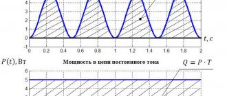
6.Operation of a resistive element in a DC circuit. Provide a diagram and timing diagrams.
7.Operation of capacitance in a DC circuit. Provide a diagram and timing diagrams.
8.Work of inductance in a DC circuit. Provide a diagram and timing diagrams.
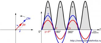
9.Operation of a resistive element in alternating current electrical circuits. What power is determined and what is it equal to over the period. Provide a diagram and timing diagrams.
10.Operation of capacitance in alternating current electrical circuits. What power is determined and what is it equal to over the period. Provide a diagram and timing diagrams.
11.Work of inductance in alternating current electrical circuits. What power is determined and what is it equal to over the period. Provide a diagram and timing diagrams.
12. An alternating current electrical circuit with a series connection of elements R, L, C. Provide a diagram of the circuit and the derivation of Ohm’s law for it.
Vector diagram
Definition 1
An unbranched electrical circuit is an electrical circuit characterized by the fact that the same current flows in all its sections.
An example of the simplest unbranched electrical circuit is shown in the figure below.
Figure 1. Unbranched electrical circuit. Author24 - online exchange of student work
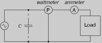
Consider the diagram of an unbranched AC electrical circuit, which is shown in the figure below.
Finished works on a similar topic
- Course work Calculation of an unbranched alternating current circuit 430 rub.
- Abstract Calculation of an unbranched alternating current circuit 230 rub.
- Test work Calculation of an unbranched alternating current circuit 230 rub.
Receive completed work or specialist advice on your educational project Find out the cost
Figure 2. Diagram of an unbranched AC electrical circuit. Author24 - online exchange of student work
The above electrical network consists of the following sections:
- Capacitor (R1 X1).
- Coils (R2 X2).
- Resistor (K3).
- Two ideal capacitors (X4 and X5).
Note 1
In this electrical circuit, the capacitor and coil are represented by active and reactive resistances.
Let's assume that, in addition to the resistances, we know the current in the circuit:
$i = Imsinwt$
We arbitrarily select the conditionally positive direction of the current, clockwise. For instantaneous quantities, according to Kirchhoff’s second law, the stress equation, in vector form, will look like this:
Need advice on your academic work? Ask a question to the teacher and get an answer in 15 minutes! Ask a Question
$U = U1a+U1p+U2a+U2p+U3a+U4p+U5p$
Numerically, the voltage vectors are determined as the product of the resistance of the corresponding section of the circuit and the current. The figure below shows a vector diagram that corresponds to this equation.
Figure 3. Vector diagram. Author24 - online exchange of student work
The current vector is taken as the initial one, and then the voltage drop vectors are drawn for each section of the circuit, the directions of the vectors of which are selected in accordance with the nature of the resistance. When constructing a vector voltage diagram, point b is selected, which coincides with the beginning of the current vector. Then, from this point, vector U5.2 is drawn, which is the vector of the reactive inductance voltage and the current vector that is 90 degrees ahead in phase, between points 5 and 6 in the diagram. From its end, a capacitance reactive voltage vector (U4p) is drawn, which lags the current by 90 degrees, between points 4 and 5 in the diagram. After this, the active voltage vector is deposited on the resistor, coinciding with the current vector (U3a), between points 3 and 4 on the diagram, etc., if you follow the circuit opposite to the direction of the current. Those points at which the beginning of the next and the end of the previous vectors converge are indicated by the same numbers as indicated in the diagram.
With this construction of a vector diagram, the voltage between any two points of the circuit under consideration can be determined by phase and magnitude by drawing a vector on the diagram between points with the same numbers. For example, the voltage between points 5 and 2 can be expressed by a vector that is drawn from point 2 to point 5, etc.
Definition 2
A topographic vector diagram is a vector diagram that was constructed in accordance with the alternation of the components of an electrical circuit.