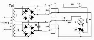
Construction and setup
If there are no installation errors, then the device operates stably.
When replacing capacitor C3, you will need to select resistors R3 and R4. Replacing thyristors in a power unit may require selecting R9, R10 (it happens that even power thyristors of the same type differ sharply in switching currents - the less sensitive one has to be rejected). You can measure the voltage across the load each time with a “suitable” voltmeter. Based on the mobility and versatility of the control unit, we used an automatic two-limit voltmeter (Fig. 7).
Voltage measurements up to 30 V are made by head PV1 type M269 with additional resistance R2 (the deviation is adjusted to the full scale at 30 V input voltage). Capacitor C1 is necessary to smooth out the voltage supplied to the voltmeter.
The rest of the circuit is used to “coarse” the scale by 10 times. The incandescent lamp of the optocoupler U1 is powered through the incandescent lamp (barretter) HL3 and the tuning resistor R3, and the zener diode VD1 protects the input of the optocoupler.
A large input voltage leads to a decrease in the resistance of the optocoupler resistor from megaohms to kilo-ohms, transistor VT1 opens, relay K1 is activated. The relay contacts perform two functions:
- open the tuning resistance R1 - the voltmeter circuit switches to the high-voltage limit;
- Instead of the green LED HL2, the red LED HL1 turns on.
Red, a more visible color, is specifically chosen for the high voltage scale.
Attention! Adjustment of R1 (scale 0...300) is carried out after adjustment of R2. The power supply to the voltmeter circuit is taken from the thyristor control unit
Isolation from the measured voltage is carried out using an optocoupler. The switching threshold of the optocoupler can be set slightly higher than 30 V, which will make it easier to adjust the scales
The power supply to the voltmeter circuit is taken from the thyristor control unit. Isolation from the measured voltage is carried out using an optocoupler. The switching threshold of the optocoupler can be set slightly higher than 30 V, which will make it easier to adjust the scales.
Diode VD2 is necessary to protect the transistor from voltage surges when the relay is de-energized. Automatic switching of voltmeter scales is justified when using the unit to power various loads. The numbering of the optocoupler pins is not given: using the tester it is not difficult to distinguish between the input and output pins.
The resistance of the optocoupler lamp is hundreds of ohms, and the photoresistor is megaohms (at the time of measurement the lamp is not powered). Figure 8 shows a top view of the device (the cover is removed). VS1 and VS2 are installed on a common radiator, VS3 and VS4 are installed on separate radiators.
The threads on the radiators had to be cut to fit the thyristors. The flexible leads of the power thyristors are cut off, the installation is carried out with a thinner wire.
Rice. 8. Top view of the device.
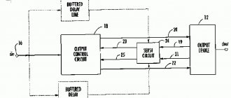
Figure 9 shows a view of the front panel of the device. On the left is the load current control knob, on the right is the voltmeter scale. LEDs are attached near the scale, the top one (red) is located near the inscription “300 V”.
The terminals of the device are not very powerful, since it is used for welding thin parts, where the accuracy of maintaining the mode is very important. The engine start-up time is short, so the terminal connections have enough life.
Rice. 9. View of the front panel of the device.
The top cover is attached to the bottom with a gap of a couple of centimeters to ensure better air circulation.
The device can be easily upgraded. Thus, to automate the car engine starting mode, no additional parts are needed (Fig. 10).
It is necessary to turn on the normally closed contact group of relay K1 from the dual-limit voltmeter circuit between points “D” and “E” of the control unit. If by adjusting R3 it is not possible to bring the voltmeter switching threshold to 12...13 V, then you will have to replace the HL3 lamp with a more powerful one (set 15 W instead of 10).
Industrial starting devices are set to a switching threshold of even 9 V. We recommend setting the switching threshold of the device to a higher voltage, since even before the starter is turned on, the battery is slightly charged with current (up to the switching level). Now the start is carried out with a slightly “recharged” battery together with an automatic starter.
Rice. 10 . Automation of the car engine starting mode.
As the on-board voltage increases, the automation “closes” the current supply from the starting device; upon repeated starts, at the right moments, the supply is resumed
The current regulator available in the device (duty factor of rectified pulses) allows you to limit the amount of inrush current
N.P. Goreyko, V.S. Stovpets. Ladyzhin. Vinnytsia region Electrician-2004-08.
Types of thyristor stabilizers
Today on the market you can see one- and two-stage thyristor voltage stabilizers. A single-stage stabilizer is one that regulates the voltage in one stage.
Two-stage ones carry out current normalization in two stages. During the first, rough leveling occurs. In the second stage, the output current receives ideal characteristics.
The two-stage control system allows the use of thyristors with greater efficiency, as the number of combinations of their inclusion increases. So, if there are four thyristors on both stages, then they can be turned on in sixteen ways.
Of course, with the increase in the number of thyristors on cascades, the number of ways to turn them on increases.
The two-stage current control method is somewhat slower than the single-stage method. It takes up to 20 milliseconds, while 1-stage lasts 10 milliseconds.
Advantages and disadvantages
So, knowing the detailed structure and operating features of a thyristor stabilizer, you can determine what advantages and disadvantages it has. Benefits include :
- No noise when current is normalized.
- One thyristor can fire more than 1 billion times, which is a very high figure.
- No arcing occurs during tripping.
- Low energy consumption.
- Small dimensions.
- High speed voltage equalization.
- High level of voltage normalization accuracy (up to ± 3 percent).
- Ability to operate at very low or high voltage levels (120-300 volts).
As for the disadvantages of the thyristor stabilizer, they lie:
- in a stepwise method of current stabilization;
- in microcontroller control. It is carried out by an electronic circuit, which is analogous to a computer processor. Accordingly, it also requires a stable current and can “freeze”;
- at a high price (this is a consequence of expensive thyristors and electronic control circuits).
How to connect?
Using thyristor voltage stabilizers in the home will protect equipment from current changes for many years. However, it must be connected before use.
Depending on the purpose, thyristor stabilizers can be connected after the meter and distribution panel (that is, they will supply stable current to the entire house), or in front of a separate device.
In the first case, thyristor devices have higher power and are connected through terminals. In this case, the input and output wires, as well as the ground wire, are connected to the terminals. When connecting both incoming and output wires, the rule is observed: the phase cable is connected to the phase terminal, and the neutral cable is connected to the neutral terminal. Grounding is also a necessary condition.
Most models that are designed to supply power to a single appliance come with a cable and outlets. Thanks to the cable, the stabilizer is connected to the network. Next, the cable plugs of the connected devices are connected to the socket located on it.
Helpful advice: in order to ground such a thyristor stabilizer, you just need to insert the plug of its cable into a three-pole socket.
terms of Use
Thyristor stabilizers are advantageous not only because they do not create noise, but also because they are unpretentious to environmental conditions. Thus, many models can operate in conditions where the air temperature exceeds -40 degrees Celsius and is less than +40 degrees Celsius.
Helpful advice: it will be better if the thyristor stabilizer is not used in frosty temperatures, even if it can work in such conditions. The ideal temperature for work will be one that exceeds +5 degrees Celsius.
A thyristor stabilizer can work perfectly in a room where the humidity level is not more than 80 percent. Some manufacturers offer stabilizers that are resistant to higher levels of humidity. However, they are made to order.
Of course, there should be no flammable objects near the thyristor device, and there should be a space of at least five centimeters around it.
Maintenance comes down to cleaning the ventilation holes and checking the quality of fastening of the input and output wires.
The operating principle of a thyristor
So in DC circuits there are two options for using a thyristor - with and without holding the open state.
After digging around, I found imported BTA triacs. The main parameters characterizing electrical energy regulators include: smoothness of adjustment; operating and peak power input; range of input operating signal; Efficiency You might think that the use of thyristors is unjustified; isn't it easier to use a regular switch?
The value of the current that can flow through the anode-cathode. For powerful devices it reaches hundreds of amperes. It allows you to switch a current of 25 A.
After switching and complete wiring, the voltage drop in the anode-cathode section remains constant at about 1 volt, for all values of the anode current from zero to the nominal value. It is located both in series and in parallel with the connected load. With high regulated power, triac VS1 must be installed on a radiator. Thyristors are made in various cases.
See also: Connecting the site to electricity vfnthbfk
Area of use of thyristor devices
In the right figure, the resistance is small, since a forward bias voltage is applied between the anode and the control electrode. Please note that the resistance value is different for different series - you should not pay special attention to this. This is the maximum permissible voltage on the thyristor in the closed state at which the thyristor can operate without affecting its performance
Zener diode VD1 limits the supply voltage to 15 V. The circuit has been assembled more than once and works without adjustment or other problems.
The main difference is a wider range of voltages. The result is a square pulse generator. But the voltage must be sufficient to light the light bulb. Thyristor circuits You can regulate the total power of the soldering iron quite simply if you use analog or digital soldering stations for this. As a result, the output is 11 DD1.
This feature lies in the fact that under normal production conditions the load can be affected by approximate voltage indicators of the household network, which will change in accordance with the sinusoidal law. Usually, correct operation of the triac can be achieved by installing transistor VT2 with a high current transfer coefficient. Another name for them is dimmers. Full technical layout of the thyristor.
From pin 1 of the DD2 chip. One control and two through which current flows. Triac (thyristor) instead of a relay.
How does a thyristor do its job?
A thyristor is a controlled semiconductor device that is capable of quickly conducting current in one direction. The word controlled means a thyristor for a reason, since with its help, unlike a diode, which also conducts the total current to only one pole, you can select a separate moment when the thyristor begins the process of conducting current.
The thyristor has three current outputs at once:
- Cathode.
- Anode.
- Controlled electrode.
To allow current to flow through such a thyristor, the following conditions must be met: the part must be located on the circuit itself, which will be under general voltage, and the required short-term pulse must be applied to the control part of the electrode. Unlike a transistor, controlling such a thyristor will not require the user to hold the control signal.
But all the difficulties of using such a device will not end there: the thyristor can be easily closed by interrupting the flow of current into it through the circuit, or by creating a reverse anode-cathode voltage. This will mean that the use of a thyristor in DC circuits is considered quite specific and in most cases completely unreasonable, and in AC circuits, for example, in a device such as a thyristor regulator, the circuit is created in such a way that the condition for closing the device is fully ensured . Any given half-wave will completely cover the corresponding section of the thyristor.
is most likely difficult for you to understand the diagram of its structure . But, there is no need to be upset - the process of functioning of such a device will be described in more detail below.
Performance monitoring
Before installing the thyristor in the circuit, you must ensure that it is in good working order. The integrity of the part is checked with a multimeter or a light bulb connected to a power source.
A dialing function is installed on the measuring device. First, the probes are connected to the anode and cathode alternately in the forward and reverse directions. The number “1” on the display will indicate that no current is flowing and the part is in good condition. Then the line from the anode to the signal contact is called.
The functionality of the part can be checked by assembling a simple electrical circuit. The anode contact is connected to the positive terminal of the battery. The cathode is connected to the negative of the power source through the light bulb. A piece of wire briefly connects the anode and control terminals. The lamp should light up and not go out after breaking the anode-control electrode chain.
A working lighting device indicates the serviceability of the thyristor. When checking, it is necessary to take into account the amount of voltage supplied, which must be sufficient to turn on the lamp.
Areas and purposes of use
First you need to understand the purposes for which a device such as a thyristor power regulator is used. Power regulators are used in almost all construction and carpentry electric tools. In addition, kitchen appliances cannot be used without them. They allow, for example, to regulate the speed modes of a food processor or blender, the air blowing speed of a hairdryer, and also function to ensure the completion of other equally important tasks. The semiconductor element allows you to more effectively regulate the power of heating devices, that is, their main part.
If you use thyristors in a circuit with a highly inductive load, they may simply not close at the right time, which will lead to equipment failure. Many users have seen or even used devices such as grinders, grinders or drills. You will notice that the power is mainly adjusted by pressing a button. This button is located in a common block with a thyristor power regulator, which changes the engine speed.
Important! A thyristor regulator cannot change speed automatically in asynchronous motors. But in a commutator engine equipped with a special alkaline unit, the adjustment will work correctly and fully.
How to test a thyristor from a separate control voltage source?
Let's return to the first circuit for testing a thyristor, from a constant voltage source, but slightly modifying it.
Look at Figure No. 3.
4. Lesson No. 4 - “Thyristor in an alternating current circuit. Pulse-phase method"
5. Lesson No. 5 - “Thyristor regulator in the charger”
These lessons, in a simple and convenient form, present basic information on semiconductor devices: dinistors and thyristors.
What is a dynistor and a thyristor, the types of thyristors and their volt-ampere characteristics, the operation of dynistors and thyristors in direct and alternating current circuits, transistor analogues of a dynistor and thyristor.
And also: methods of controlling electrical power of alternating current, phase and pulse-phase methods.
Each theoretical material is confirmed by practical examples. Operating circuits are presented: a relaxation generator and a fixed button, implemented on a dinistor and its transistor analogue; short circuit protection circuit in the voltage stabilizer and much more.
Particularly interesting for car enthusiasts is the circuit of a 12-volt battery charger using thyristors. Diagrams of the voltage waveform are presented at the operating points of existing alternating voltage control devices using phase and pulse-phase methods.
To receive these free lessons, subscribe to the newsletter, fill out the subscription form and click the “Subscribe” button.
Good evening habr. Let's talk about such a device as a thyristor. A thyristor is a bistable semiconductor device having three or more interacting rectifying junctions. In terms of functionality, they can be compared to electronic keys. But there is one feature in the thyristor: it cannot go into the closed state, unlike a regular key. Therefore, it can usually be found under the name - not fully managed key.
The figure shows a typical view of a thyristor. It consists of four alternating types of electrical conductivity of semiconductor regions and has three terminals: anode, cathode and control electrode. The anode is in contact with the outer p-layer, the cathode is in contact with the outer n-layer. You can refresh your memory about pn junction.
Principle of operation
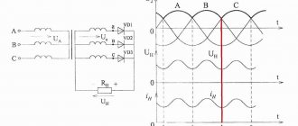
In connection with this pattern, the outer regions can be called emitter, and the central junction can be called collector. To understand how a thyristor works, you should look at the current-voltage characteristic. A small positive voltage is applied to the anode of the thyristor. The emitter junctions are connected in the forward direction, and the collector junctions in the reverse direction. (essentially all the tension will be on it). The section from zero to one on the current-voltage characteristic will be approximately similar to the reverse branch of the diode characteristic. This mode can be called the thyristor closed state mode. As the anode voltage increases, majority carriers are injected into the base region, thereby accumulating electrons and holes, which is equivalent to the potential difference at the collector junction. As the current through the thyristor increases, the voltage at the collector junction will begin to decrease. And when it decreases to a certain value, our thyristor will go into a state of negative differential resistance (section 1-2 in the figure). After this, all three transitions will shift in the forward direction, thereby transferring the thyristor to the open state (section 2-3 in the figure). The thyristor will remain in the open state as long as the collector junction is biased in the forward direction. If the thyristor current is reduced, then as a result of recombination the number of nonequilibrium carriers in the base regions will decrease and the collector junction will be biased in the opposite direction and the thyristor will go into the off state. When the thyristor is turned on in reverse, the current-voltage characteristic will be similar to that of two diodes connected in series. The reverse voltage will be limited in this case by the breakdown voltage.
General parameters of thyristors
Turn-on voltage Forward voltage Reverse voltage
permissible voltage
Maximum permissible forward current Reverse current Maximum electrode control current On/off delay time Maximum permissible power dissipation
Methods for closing a thyristor
Turning off the thyristor by changing the polarity of the voltage between the cathode and the anode.
Applying a pulse to the control electrode is unable to stop its operation or close it. The modulator only turns on the thyristor. The termination of the latter action occurs only after the current supply is interrupted at the cathode-anode stage.
The voltage regulator on the Ku202n thyristor is closed in the following ways:
- Disconnect the circuit from the power supply (battery). The device will not work until a special button is pressed.
- Loosen the anode-cathode connection using a wire or tweezers. All the voltage goes through these elements, entering the thyristor. If the jumper is opened, the current level will be zero and the device will turn off.
- Reduce voltage to minimum.
Thyristor control
In power electronic devices, either phase or pulse-width thyristor control is most often used.
In the first case, the current load can be adjusted by changing the angles either α or θ. This refers to forced loading. The artificial load can only be adjusted using a controlled thyristor, also called a turn-off thyristor.
With PWM (pulse width modulation), during Totkr the signal is supplied, which means that the device itself is in the open state, that is, the current is supplied with voltage Un. During the Tclose time period there is no signal, and the device itself is in a non-conducting state.
How to check a thyristor?
Preliminary testing of the thyristor is carried out using an ohmmeter tester or digital multimeter
.
The DMM switch should be in the diode test position. Using an ohmmeter or multimeter, the thyristor transitions are checked: control electrode - cathode
and anode - cathode transition
.
The transition resistance of the thyristor, control electrode - cathode, should be in the range of
50 - 500 Ohms.
In each case, the value of this resistance should be approximately the same for forward and reverse measurements. The greater the value of this resistance, the more sensitive the thyristor. In other words, the value of the control electrode current at which the thyristor moves from the closed state to the open state will be less. In a working thyristor, the resistance value of the anode-cathode transition, during direct and reverse measurements, should be very large, that is, it should have an “infinite” value. The positive result of this preliminary test does not mean anything. If the thyristor was already installed somewhere in the circuit, it may have a “burnt out” anode-cathode transition. This thyristor malfunction cannot be determined with a multimeter.
The main test of the thyristor must be carried out using additional power supplies. In this case, the operation of the thyristor is completely checked. The thyristor will go into the open state if a short-term current pulse sufficient to open the thyristor passes through the transition, cathode - control electrode.
This current can be obtained in two ways: 1. Use the main power source and resistor R, as in Figure No. 1. 2. Use an additional control voltage source, as in Figure No. 2.
Let's look at the thyristor testing circuit in Figure No. 1.
You can make a small test board on which to place wires, an indicator light and switch buttons.
Multi-position switch circuits
In Fig. 10 and 11 show a thyristor switch of a discontinuous type with an unlimited number of series-connected elements.
When one of the control buttons is pressed, the power supply circuit of the thyristor analogues opens to DC current. Capacitor C1 is connected in series with the thyristor analogue.
Rice. 10. Diagram of the basic element for a homemade multi-position load switch.
Rice. 11. Schematic diagram of a homemade multi-position load switch.
At the same time, the control voltage (zero level) through the activated button and resistor R2 (Fig. 10) is supplied to the control electrode of the thyristor analogue.
Since in the first moments when the button is pressed, a completely discharged capacitor turns on in series with the thyristor analogue, such inclusion is equivalent to a short circuit in the power circuit of the corresponding thyristor. Consequently, the thyristor is turned on, thereby turning on the corresponding load.
When you press any other button, the previously activated channel is turned off and another channel is turned on. When you press any button for a long time (about 2 seconds), capacitor C1 is charged, which is equivalent to opening the circuit and leads to the locking of all thyristors.
Example of calculation of a simple circuit
For example, let's say you want to turn an LED on and off using a microcontroller. Then the control diagram will look like this.
Let the supply voltage be 5 V.
The characteristics (operating current and voltage drop) of typical 5 mm LEDs can be approximately estimated from the table.
| Color | ||
| Red | 20 mA | 1.9 V |
| Green | 20 mA | 2.3 V |
| Yellow | 20 mA | 2.1 V |
| Blue (bright) | 75 mA | 3.6 V |
| White (bright) | 75 mA | 3.6 V |
Let's use a white LED. We use KT315G as a transistor switch - it is suitable for the maximum current (100 mA) and voltage (35 V). We will assume that its current transfer coefficient is equal to (smallest value).
So, if the voltage drop across the diode is equal to , and the saturation voltage of the transistor, then the voltage across resistor R2 will be equal to . For the operating current of the LED we obtain
The resistance value has been rounded to fit into the E12 range.
For current, the control current must be a factor of less:
Let us take the voltage drop across the emitter-base junction to be equal to .
From here
The resistance was rounded down to provide a current margin.
Thus, we found the values of resistances R1 and R2.
Controlling thyristors in microcontroller circuits
A thyristor is a four-layer semiconductor device consisting of sequentially alternating regions of p- and “-types of conductivity. Until 1979, thyristors were called thyristors. With the advent of GOST 20859.1-79, and then GOST 20859.1-98, the classification changed as follows:
• triode thyristors or, in short, thyristors;
• thyristors-diodes (thyristors with a built-in reverse diode);
• avalanche, asymmetrical, lockable thyristors;
• combined-switchable thyristors;
• symmetrical triode thyristors or, in other words, triacs, triacs;
• photothyristors, optothyristors, optosimistors.
The three terminals of the thyristor are designated by the letters: “A” (anode, Anode), “K” or “C” (cathode, Cathode), “UE” or “G” (control electrode or Gate).
The power of the load connected to the anode/cathode of the thyristor is many times greater than the power of the control signal. An important feature of the thyristor is that once open, it remains in this state constantly, until the power is completely removed. Therefore, short pulses can be used to control the thyristor.
Depending on the semiconductor layer with which the UE output is internally connected, thyristors can be cathode controlled (Fig. 2.102, a, more common) and anode controlled (Fig. 2.102, b, less common).
Rice. 2.102. Conventional graphic designations of thyristors: a) with cathode control; b) with anode control.
Among the many electrical parameters of thyristors, the following are of interest from the point of view of interfacing with MK:
• unlocking current UE /ue (tens to hundreds of milliamps);
• maximum voltage UE (units to tens of volts);
• Duration of the switching pulse Tvkl (microseconds).
Typical parameters of thyristors of the KU221 family: /ue = 0.15 A; b emlh = 7 V; Gvkl MIN = 2 MK s (in real circuits they set 50 MK s...10 ms); The pulse repetition frequency at the input of the UE should be no more than 30 kHz. The remaining parameters relate to the power section. They depend on the power/voltage of the load and must be selected separately, without reference to the MK circuit design.
To ensure long-term reliability of thyristors, you should adhere to a set of simple rules:
• the UE pulse must have a current margin relative to the minimum permissible, otherwise a local breakdown of the structure with a weak interference current may occur and the thyristor may fail [2-187];
• operating voltages and currents in the power section must be selected with a safety factor of 0.7...0.8 from the maximum allowed according to the datasheet;
• the electrical parameters of the UE input have a significant technological spread, so calculations of the elements must be carried out for the worst case. However, some instances of thyristors can also be turned on at lower (compared to the datasheet) currents and voltages, which is often used by radio amateurs in their designs;
• to increase noise immunity, it is recommended to install a resistor with a resistance of 51... 1000 Ohms between the cathode and the UE. Another solution is to provide a low output impedance to the control pulse generator;
• a comfortable temperature regime should be created for the thyristor using radiators and heat-conducting pastes, for example, KTP-8.
When switching a load in a 220 V circuit, it is advisable to synchronize the control pulses with the moments when the mains voltage crosses zero. This technique sharply reduces the level of high-frequency interference that “clogs” the airwaves. To smoothly change the voltage in the load, phase number-pulse control is used, and it does not matter how the thyristors are connected to the MK: without isolation from the 220 V network (Fig. 2.103, a...g) or with galvanic isolation (Fig. 2.104, a ...n).
a) pulses from the MK output periodically open the transistor K77, and through it the thyristor VS1. The average voltage in the load RH will change depending on the pulse repetition rate. The optional capacitor C7 reduces RF interference at the moment of switching;
b) similar to Fig. 2.103, ah, but in the most simplified way. However, it really works;
c) thyristor VS1 is powered by a constant, not pulsating voltage, so it is turned on by a positive pulse from the MK output, and turned off by completely removing the supply voltage +9...+ 18 V;
d) similar to Fig. 2.103, v, but without a transistor and turning off the thyristor VS1 by pressing the SB1 button. Resistor R1 sets the control current to no more than 15 mA. The voltage drop across the thyristor in the open state is 0.6…1.5 V. The contacts of the SB1 button must withstand the maximum current for which the load RH\ is designed
e) microcircuit DD1 has an open collector output and serves as a key that opens thyristor VS1. Resistor R1 sets the control current, but it may not be enough for a particular thyristor due to the low supply voltage of +5 V (tested experimentally);
Rice. 2.103. Diagrams for connecting thyristors to MK without galvanic isolation (end):
f) classic connection of shunt resistor R3 between the input of the UE and the cathode of the VSI thyristor. The +5V supply voltage for MK can be obtained from +9V via a regulator;
g) a voltage increased to +12 V is supplied to the input of the UE thyristor VS1 through resistor R3 to ensure guaranteed unlocking. In some cases, by selecting the type of thyristor VS1, it is possible to turn it on at a reduced voltage of +5 V. The optional capacitor C/ somewhat slows down the rate of rise of the control current (at the same time power losses increase), but it protects the thyristor VS1 from false alarms.
Rice. 2.104. Schemes of galvanic isolation of MK from thyristors (beginning):
a) galvanic isolation through optocoupler VU1. Thyristor VS1 supplies voltage to the load Rn only during one half-cycle of the 220 V mains voltage. During the other half-cycle, the load is de-energized because diode VD2 is closed. Zener diode VD1 sets the optimal voltage at the input of the UE thyristor VS1. Resistor R2 limits the control current;
b) similar to Fig. 2.104, a, but with a different polarity of pulses from MK, with an additional resistor R2, with a filter capacitor C1 and with a different zener diode VD1\
c) LOW and HIGH levels must be set synchronously at both outputs of the MK. Resistors R1, &2 are current limiting. Resistor R4 increases noise immunity;
d) galvanic isolation on transformer T1. Each of the thyristors VS1, VS2 opens into its own half-wave of the mains voltage by pulses from the output of the MK with a duration of 10 MK s and a period of 0.7...1 ms. To power transistor VT1, a separate +5 V(2) source is used so that interference does not interfere with the operation of the MK. Transformer T1 is wound on a ferrite ring 79HM K25xl5x5, in winding I - 40 turns, in windings II, III - 80 turns of PEV-0.25 wire;
e) MK generates pulses with a frequency of 100 Hz and a duration of 12 MK s, which gradually shift over 3 s from the end of the half-cycle of the network sinusoid to its beginning. As a result, the optosimulator VU1 “in small steps” goes into a fully open state, organizing a smooth charge of the capacitance of the high-voltage capacitor C3. Choke L1 is wound on a ferrite ring M2000HM1 K31xl8.5×7 and contains two windings of 25 turns of PEV-1.0 wire each;
f) switching the load RH using thyristor VS1 and isolated opto-relay VU1\
g) galvanic isolation of MK is performed on optocoupler VU1. Transformer T1 is not used for isolation (the RH load is already connected to a 220 V network), but to unlock the thyristor VS1 with an increased voltage of +9...+12 V at a current of up to 0.15 A. Economically, this solution is justified in a multi-channel system with a large number of thyristors and one transformer;
h) VU1 - dual opto-thyristor module. MK lines are paralleled to increase power. Replacement VU1 - two optothyristors TO 125-10-6;
i) galvanic isolation on the optosimistor VU1. Thyristors VS1, K£2 are connected in opposite directions. Each of them opens at “its own” half-cycle of the mains voltage;
j) the optocoupler thyristor VU1 closes the diagonal of the diode bridge VD1 to switch the load RH in both half-cycles of the mains voltage. Current through the load is no more than 100 mA;
k) similar to Fig. 2.104, k, but with a different polarity of pulses and other types of ERI;
Rice. 2.104. Schemes for galvanic isolation of MK from thyristors (end):
m) strobe with optical isolation. Thyristor VS1 through step-up transformer T1 [2-196] periodically ignites lamp EL1. The HL1 LED indicates strobe flashes;
n) the markings on the body of optothyristors VU1, G772 contain letters and symbols instead of the usual Arabic numerals. Load power RH no more than 100 W.
Source: Ryumik, S.M., 1000 and one microcontroller circuit. Vol. 2 / S. M. Ryumik. - M.: LR Dodeka-XX1, 2011. - 400 pp.: ill. + CD. — (Series “Programmable Systems”).
Tweet Like
- Previous post: Strobing LEDs on MK
- Next entry: Radio tubes from the Odessa Radio Plant
- What is the difference between current and voltage? (2)
- Current and Voltage Relationship (0)
- POWER SUPPLY FOR CAR RADIO (0)
- BATTERY ELECTRICAL ISOLATION DEVICE (0)
- BATTERY CHARGER (0)
- LITHIUM-NON CELL CHARGER CHARGER CONTROLLER (0)
- BATTERY CHARGING CURRENT LIMITER (0)
Related posts:
Finalization of the scheme
If the input of the circuit is connected to the push-pull output, then no special modification is required. Consider the case where the input is simply a switch that either pulls the base to power or leaves it “hanging in the air.” Then, to reliably close the transistor, you need to add another resistor to equalize the voltage between the base and emitter.
In addition, you need to remember that if the load is inductive, then a protective diode is required. The fact is that the energy stored in the magnetic field does not allow the current to instantly decrease to zero when the key is turned off. This means that a voltage of reverse polarity will arise at the load contacts, which can easily disrupt the operation of the circuit or even damage it.
The advice regarding the protective diode is universal and equally applies to other types of keys.
If the load is resistive, then a diode is not needed.
As a result, the improved scheme takes the following form.
Resistor R2 is usually taken with a resistance 10 times greater than the resistance of R1, so that the divider formed by these resistors does not reduce the voltage between the base and emitter too much.
For relay loads, a few more improvements can be added. It usually consumes high current for a short time only at the moment of switching, when energy is wasted to close the contact. The rest of the time, the current through it can (and should) be limited by a resistor, since maintaining contact requires less energy.
To do this, you can use the diagram below.
When the relay is turned on, while capacitor C1 is not charged, the main current flows through it. When the capacitor is charged (and by this time the relay will switch to contact holding mode), the current will flow through resistor R2. The capacitor will also discharge through it after the relay is turned off.
Capacitance C1 depends on the relay switching time. You can take, for example, 10 µF.
On the other hand, the capacitance will limit the relay switching frequency, albeit by an amount that is insignificant for practical purposes.
Practical use
Due to the operating principle, the thyristor is used in voltage converters and current rectifiers. Together with a power transformer, the semiconductor is able to change the current level. Car battery chargers, as well as powerful electric welding machines, are assembled on this basis. The ability of the device to change alternating voltage to direct voltage is used in converters.
In alarm devices, the thyristor is turned on by a command from an external sensor that changes the voltage on the control electrode. Designs that control the environment can respond to changes in temperature or volumetric filling of the space. The illumination of the object is monitored by an optothyristor.
Maintaining the specified temperature in the furnace is ensured by a combustion arc power regulator. In electric motors, the rotation speed of the drive shaft is controlled by a thyristor speed controller.
Archimedes promised to turn the Earth upside down if he had a fulcrum. The controlled thyristor semiconductor is the lever that expands the applications of electronic devices. A small radio component multiplies human capabilities in the development of scientific and technological progress.
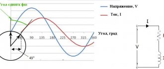
Phase voltage regulation
There are several ways to regulate alternating voltage with thyristors: you can pass or inhibit entire half-cycles (or periods) of alternating voltage from the regulator output. And you can turn it on not at the beginning of the half-cycle of the mains voltage, but with some delay - 'a'. During this time, the voltage at the regulator output will be zero, and no power will be transferred to the output. The second part of the half-cycle the thyristor will conduct current and the input voltage will appear at the output of the regulator.
The delay time is also often called the opening angle of the thyristor, and so at zero angle, almost all the voltage from the input will go to the output, only the drop across the open thyristor will be lost. As the angle increases, the thyristor voltage regulator will reduce the output voltage.
The regulating characteristic of a thyristor converter when operating on an active load is shown in the following figure. At an angle of 90 electrical degrees, the output will be half the input voltage, and at an angle of 180 electrical degrees. the output degrees will be zero.
Based on the principles of phase voltage regulation, it is possible to construct regulation, stabilization, and soft start circuits. For a smooth start, the voltage must be increased gradually from zero to the maximum value. Thus, the opening angle of the thyristor should vary from the maximum value to zero.
Fast switching circuit
As already mentioned, if the voltage at the gate relative to the source exceeds the threshold voltage, then the transistor opens and the drain-source resistance is low. However, the voltage when turned on cannot suddenly jump to the threshold. And at lower values, the transistor acts as a resistance, dissipating heat. If the load has to be turned on frequently (for example, in a PWM controller), then it is advisable to switch the transistor from the closed state to the open state and back as quickly as possible.
The relative slowness of the transistor switching is again related to the parasitic gate capacitance. In order for the parasitic capacitor to charge as quickly as possible, you need to send as much current as possible into it. And since the microcontroller has a limit on the maximum output current, this current can be directed using an auxiliary bipolar transistor.
In addition to charging, the parasitic capacitor also needs to be discharged. Therefore, a push-pull circuit using complementary bipolar transistors seems optimal (you can take, for example, KT3102 and KT3107).
Once again, pay attention to the location of the load for the n-channel transistor - it is located “on top”. If you place it between the transistor and ground, due to the voltage drop across the load, the gate-source voltage may be less than the threshold, the transistor will not open completely and may overheat and fail
Seven thyristor voltage regulators
With phase-pulse control
The regulator, the diagram of which is shown in Fig. 2, controlled automatically by Uynp signal. The regulator uses two thyristors - thyristor D5 and dinistor D7. The thyristor opens with pulses that are formed by a chain consisting of dinistor D7 and capacitor C1. At the beginning of each half-cycle, the thyristor and dinistor are closed and capacitor C1 is charged by the collector current of transistor T1. When the voltage on the capacitor reaches the opening threshold of the dinistor, it will open and the capacitor will quickly discharge through resistor R2 and the primary winding of transformer Tr1. A current pulse from the secondary winding of the transformer will open the thyristor. In this case, the control device will be de-energized (since the voltage drop across the open thyristor is very small), and the dinistor will close. At the end of the half-cycle, the trinnstor will turn off and with the beginning of the next half-cycle, a new cycle of operation of the regulator will begin.
The delay time of the pulse that opens the thyristor relative to the beginning of the half-cycle is determined by the charging rate of capacitor C1, which is proportional to the collector current of transistor T1. By changing the control voltage Uynp, it is possible to control this current and ultimately regulate the voltage across the load. The source of the Uynp signal can be a bandpass filter (with a rectifier) of a color music installation or a software device. In automatic control systems, feedback voltage is used as Ucontrol.
Resistor R5 must be selected such that when Uynp = 0 the thyristor opens in each half-cycle at a time close to the end of the half-cycle. In order to switch to manual regulation, it is enough to replace resistor R5 with a series chain of a variable resistor and a constant resistance of 10-12 kOhm. The stabilization voltage of zener diode D6 should be 5-10 V greater than the maximum turn-on voltage of the dinistor.
Transistor T1. can be any of the MP21, MP25, MP26 series. The dinistor can be used types KN102B, D227A, D227B, D228A, D228B. Resistor R1 is made up of two with a power of 2 W each. Pulse transformer Tr1 is wound on a ring core with dimensions 26X18X4 mm, made of 79NMA permalloy (or the same cross-section made of M2000NM1 ferrite). Winding I contains 70 turns, and winding II contains 50 turns of PEV-2 0.33 mm wire. The interwinding insulation must withstand voltage close to the mains voltage. Instead of a dinistor in the regulator, you can use a transistor operating in avalanche mode. The operation of transistors in this mode was described in detail in Radio, 1974, No. 5, pp. 38-41. The diagram of one of these regulators is shown in Fig. 3.
According to the principle of operation, the regulator with a transistor operating in avalanche mode is no different from the previous one. The GT311I type transistor used has an avalanche breakdown voltage of about 30 V (with a resistance of resistor R3 equal to 1 kOhm). If other transistors are used, the values of elements R4, R5, C1 will need to be changed.
The regulator (Fig. 3) can also use other transistors, including pnp structures, for example P416. In this case, you need to swap the emitter and collector terminals of transistor T1 (see Fig. 3). Resistor R3 in all cases must be connected between the base and emitter. The load voltage is regulated by variable resistor R4.
Eng.
E. FURMANSKY Moscow With an analogue of a unijunction transistor
In the regulator, the circuit of which is shown in Fig. 4, the phase-pulse method of controlling the thyristor is applied. The control device of the regulator uses a transistor analogue of a unijunction transistor (double-base diode). You can read about the operation of unijunction transistors in Radio, 1972, No. 7, p. 56.
The power circuit of the regulator is constructed in the same way as that of the regulator published in Radio, 1972, No. 9, p. 55. When the contacts of switch B'2 are open, the effective value of the voltage at the load can be changed within the range from several volts to 110 V, and when the contacts are closed - from 110 to 220 V.
According to the principle of operation, the control device of the described regulator does not differ from devices based on a dinistor or avalanche transistor (Fig. 2 and 3). The power supplied to the load is controlled by variable resistor R5.
SCR DZ and diode D1 are installed on a common radiator with an area of 50-80 cm2. Resistor R1 is made up of two 2 W resistors.
Eng.
V. POPOVICH, Izhevsk. On a triac
The described regulator is built according to a phase-pulse control circuit using a triac (symmetrical thyrnstor). The regulator diagram is shown in Fig. 5. The control device uses a transistor analogue of an n-type unijunction transistor.
When the regulator is turned on (by switch B1), transistors T1 and T2 are closed and capacitor C1 begins to charge through resistor R4 (with the help of which the power released to the load Rн is regulated). The charge continues until the voltage on the capacitor exceeds the opening threshold of transistor T1. At this moment, the transistors open and go into saturation mode. The capacitor quickly discharges through them to the primary winding of the pulse transformer Tr1. A current pulse from the secondary winding opens triac D5. The opening threshold of the transistors is determined by the resistances of the divider resistors R2R3.
Pulse transformer Tr1 is wound on a ferrite ring M2000NM1-15 of standard size K20x 12x6. Winding I contains 50 turns, and winding II contains 30 turns of 0.25 mm PELSHO wire. Capacitor C1 is an MBM with an operating voltage of 160 V.
The maximum permissible load current of the regulator is 5 A. The voltage regulation limits are from several volts to 215 V.
Eng.
V. PONOMARENKO. Eng. V. FROLOV, Voronezh With improved control characteristics
In thyristor regulators with phase-pulse control, the voltage on the capacitor of the RC circuit during its charging increases according to an exponential law. With a sinusoidal form of the mains voltage, the regulation characteristic, which expresses the dependence of the voltage on the load on the resistance of the variable resistor, turns out to be sharply nonlinear, which makes it difficult to smoothly regulate the voltage on the load.
Thyristor regulator, the circuit of which is shown in Fig. 6 is largely free from this drawback. The regulator uses a unijunction transistor. Improving the linearity of the adjustment characteristic is achieved by the fact that capacitor C1 is charged from the mains voltage (through resistor R4) and at the same time from a source of constant stabilized voltage (through divider R5R6 and diode D6). By changing the level of constant voltage with resistor R6, you can control the opening moment of the thyristor and, therefore , voltage across the load.Diode D6 eliminates the possibility of discharging the capacitor through resistor R6.
The resistance of resistor R4 is chosen such that when resistor R6 is short-circuited, the voltage across the load is minimal.
Then, at the lowest (according to the diagram) position of the resistor R6 motor, the voltage across the load will be maximum. With output voltage stabilization
A feature of the described regulator is the ability to stabilize the load voltage when the supply voltage changes. The control device is built on a unijunction transistor according to a phase-pulse control circuit.
Source: shems.h1.ru
Inductive Load Control
When driving an inductive load such as an electric motor, or when there is noise on the line, the voltage may become high enough to cause the triac to open spontaneously. To combat this phenomenon, it is necessary to add a snubber to the circuit - this is a smoothing capacitor and a resistor in parallel with the triac.
The snubber doesn't improve the emissions situation much, but it's better with it than without it.
The ceramic capacitor must be designed for a voltage greater than the peak in the power supply. Let us remember once again that for 230 V this is 325 V. It is better to take it with a reserve.
Typical values: , .
There are also triac models that do not require a snubber. For example, BTA06-600C.
Scheme number 1
There was a stabilized switching power supply that gave an output voltage of 17 volts and a current of 500 milliamps. A periodic change in voltage was required in the range of 11 - 13 volts. And the well-known voltage regulator circuit on one transistor coped with this perfectly. I added only an indication LED and a limiting resistor to it. By the way, the LED here is not only a “firefly” signaling the presence of output voltage. With the correct value of the limiting resistor, even a small change in the output voltage is reflected in the brightness of the LED, which provides additional information about its increase or decrease. The output voltage could be changed from 1.3 to 16 volts.
KT829, a powerful low-frequency silicon compound transistor, was installed on a powerful metal radiator and it seemed that, if necessary, it could easily withstand a heavy load, but a short circuit occurred in the consumer circuit and it burned out. The transistor has a high gain and is used in low-frequency amplifiers - you can really see its place there and not in voltage regulators.
On the left are removed electronic components, on the right are prepared for replacement. The difference in quantity is two items, but in terms of the quality of the circuits, the former and the one that was decided to be collected, it is incomparable. This begs the question: “Is it worth assembling a scheme with limited capabilities when there is a more advanced option “for the same money”, in the literal and figurative sense of this saying?”
Using the regulator in everyday life and safety precautions
It must be said that this circuit does not provide galvanic isolation from the network, so there is a danger of electric shock. This means that you should not touch the regulator elements with your hands. An insulated housing must be used. You should design the design of your device so that, if possible, you can hide it in an adjustable device and find free space in the case. If the adjustable device is located permanently, then in general it makes sense to connect it through a switch with a dimmer. This solution will partially protect against electric shock, eliminate the need to find a suitable housing, has an attractive appearance and is manufactured using an industrial method.
Scheme of a thyristor power regulator with one and two thyristors
A typical circuit for assembling a thyristor power regulator with your own hands is shown in the figure below.
The output voltage of this circuit is from 15 to 215 volts; in the case of using the indicated thyristors installed on heat sinks, the power is about 1 kW. By the way, the switch with the light brightness control is made according to a similar scheme.
If you don't need to fully regulate the voltage and just need to get an output of 110 to 220 volts, use this diagram, which shows a half-wave power regulator on a thyristor.
Let's check the thyristor when powering the circuit with direct current.
As a load resistance and a visual indicator of the operation of the thyristor, we will use a low-power light bulb at the appropriate voltage. Resistor value R
is selected on the basis that the current flowing through the control electrode - the cathode - is sufficient to turn on the thyristor.
The thyristor control current will pass through the circuit: plus (+) – closed button Kn1 – closed button Kn2 – resistor R – control electrode – cathode – minus (-). The thyristor control current for KU202 according to the reference book is 0.1 ampere. In reality, the thyristor turn-on current is somewhere between 20 and 50 milliamps and even less. Let's take 20 milliamps, or 0.02 amperes. The main power source can be any rectifier, battery or set of batteries. The voltage can be anything from 5 to 25 volts.
's determine the resistance of the resistor R. Let us take for calculation a power source U = 12 volts. R = U: I = 12 V: 0.02 A = 600 Ohm.
Where: U – power source voltage; I – current in the control electrode circuit.
The value of resistor R will be equal to 600 Ohms.
If the source voltage is, for example, 24 Volts, then R = 1200 Ohms.
The circuit in Figure 1 works as follows.
In the initial state, the thyristor is closed, the light bulb does not light. The circuit can remain in this state for as long as desired. Press the Kn2 button and release. A control current pulse will flow through the control electrode circuit. The thyristor will open. The light will light even if the control electrode circuit is broken. Press and release the Kn1 button. The load current circuit passing through the thyristor will break and the thyristor will close. The circuit will return to its original state.
Characteristics and their meaning
Some thyristors can switch very high currents, in which case they are called power thyristors. They are made in a metal case for better heat dissipation. Small models with a plastic body are usually low-power options that are used in low-current circuits. But, there are always exceptions. So for each specific purpose, the required option is selected. They select, of course, according to parameters. Here are the main ones:
- Maximum forward current. The value of the current that can flow through the anode-cathode. For powerful models it can reach hundreds of Amperes.
- Maximum permissible reverse current. Not indicated for all types, only for reverse-conducting ones.
- Direct voltage. This is the maximum permissible voltage drop in the on-state when the maximum current passes.
- Turn-on voltage. The minimum level of the control signal at which the thyristor will operate.
- Holding current. If the current flowing through the anode-cathode is below this value, the device goes into a locked state.
- Minimum control signal current. If a current is supplied below this value, the element will not open.
- Maximum control current. If this parameter is exceeded, the pn junction will fail.
- Power dissipation. Determines the size of the connected load.
There is also a dynamic parameter - the time of transition from closed to open state
In some schemes this is important. The type of speed may also be indicated: by unlocking time or by locking time
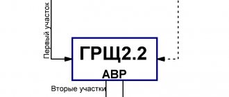
D) Protection against output current unbalance
Unbalance of three-phase load currents of more than 10-20% can be caused by a strong imbalance of phase resistances and voltages, but more often by damage to the load, breakage of load wires or incorrect connection of the load. Therefore, the activation of this protection will promptly inform the operator about the emergency situation that has arisen.
An important aspect that affects the reliability of the device is the type of cooling fans used and how they are controlled. Fans are divided into:
- by rotation speed at low, medium and high speed;
- by type of bearing - plain bearing and rolling bearing.
The best option is a high-speed fan with a rolling bearing. Such a fan provides maximum speed of air flow passing through the fins of the cooling radiator, and its rolling bearing provides a long service life (2-3 times higher than a plain bearing). The best way to control the fan is the control method using a temperature sensor installed on the radiator; for example, the fan is turned on at a radiator temperature of 55 C, and turned off at 45 C. This method increases the life of the fan by 1.5-2 times, since the fan turns off at low ambient temperatures or low load.
Another important component that affects the reliability of the thyristor regulator is the current-limiting reactor, the use of which makes it possible to extend the service life of thyristors by 1.5-2.5 times. The reactor is an inductor that reduces the rate of rise of current through the thyristors when they are turned on. The current-limiting reactor also reduces the level of electromagnetic interference. Most often, the reactor is not included in the standard delivery package; most manufacturers supply it as an optional accessory.
The best models of thyristor power regulators have the ability to operate in current limiting or stabilizing mode. The purpose of the current limiting mode is to prevent the load current from exceeding a pre-programmed value. In this case, the value of the maximum output current is entered into the microprocessor memory; the control system adjusts the control action on the thyristors so that the load current does not exceed the value of this setting. Using this mode allows you to accurately limit inrush currents, avoiding overloads and tripping of protections. Limiting the output current can also be useful depending on the process conditions. A further development of this mode is the current stabilization mode, in which the current is stabilized at a given level and maintained regardless of changes in the network voltage and load resistance.
As a rule, the thyristor regulator can be controlled locally (buttons, toggle switches, variable resistor from the control panel) or remotely using standard analog interfaces 0-10 V, 0-20 mA, 4-20 mA, compatible with any industrial controllers.
Some manufacturers of thyristor controllers, in agreement with customers, equip their devices with PID temperature controllers, the output signal of which sets the output voltage of the thyristor controller. This allows you to create a full-fledged automatic temperature control system for an object with closed temperature feedback, for which it is necessary to install a temperature sensor on the object and connect it to the measuring input of the PID controller. Using the PID controller, you can set the desired temperature, heating and cooling rates, and set an alarm to trigger when the temperature goes out of the acceptable range. The PID controller is controlled by buttons from the control panel or remotely via an interface cable from a personal computer. In the latter case, it becomes possible to create a full-fledged SCADA system with visualization of the technological process and display of controlled quantities on a mnemonic diagram.
Thyristor in an electrical circuit: what kind of semiconductor is it
If we use scientific terms, we can see that the design of this complex electronic device includes a semiconductor single crystal with three or more pn junctions.
They are made in order to change its conductivity to two critical states, when it:
- It is open and allows electric current to pass through it.
- Completely closed.
To connect to an electrical circuit, it is usually equipped with three, two or four leads from the contact pads of the pn layers.
I will not continue this topic in scientific language, because beginners will not understand anything, and it is difficult for me to explain in simple terms how charge carriers (holes and electrons) move throughout this structure in each specific case.
And no one needs this now except students trying to pass an exam, and workers designing and developing new devices.
A home electrician simply needs to understand the operating principle of the final device in order to be able to check its serviceability and competently operate it in everyday life.
Therefore, I show the final result - what the volt-ampere characteristic of the thyristor looks like during its operation.
It highlights two areas of the operating state with direct and reverse application of voltage, forming five modes depicted in the picture. Let’s not go deep into the theory and draw some brief conclusions for ourselves:
- at the initial stage of the forward bias region, the semiconductor is closed, then it opens and remains open;
- when connected back to the voltage source, it initially does not pass current, but when it reaches a critical state, it breaks through.