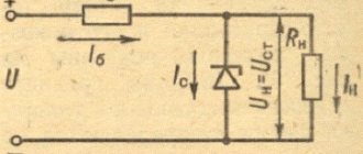
Design and principle of operation of thyristor and triac stabilizers
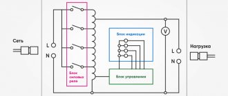
The main components of these voltage stabilizers are:
- power autotransformer - used to correct the mains voltage;
- electronic control circuit (usually implemented on a microprocessor basis) – controls all functions of the stabilizer in accordance with signals from sensors of network parameters and load power consumption;
- block of switching power semiconductor switches (thyristors or triacs) - used for switching taps of the windings of a power autotransformer;
- network interference filtering devices – suppress pulse and high-frequency interference.
On the body of electronic stabilizers, as a rule, there is an LCD display and LED indicators that display the values of the operating parameters of the device: voltage values at the input and output, power of the connected load.
The operating principle of thyristor and triac stabilizers is the same. The input alternating mains voltage is supplied to a converting autotransformer - a type of transformer whose primary and secondary windings are connected, that is, they are not only electromagnetically coupled, but also electrically connected. The secondary voltage is removed from one of several terminals of the autotransformer winding. Connection to each terminal uses a different number of turns of the transformer coil, which will determine the transformation ratio and, accordingly, the output voltage. The most similar operating principle is the relay type of stabilizers.
The parameters of the input and output voltage of the autotransformer are constantly monitored by the microprocessor of the control board. If they deviate from the norm in any direction, the microprocessor sends a control signal to turn on a specific power switching device - a semiconductor switch. Depending on the type of power switches used, a distinction is made between thyristor (using thyristors) and triac (respectively, using triacs) devices.
How to check the functionality of a triac?
You can find several methods online that describe the testing process using a multimeter; those who described them, apparently, have not tried any of the options themselves. In order not to be misleading, you should immediately note that testing with a multimeter will not be possible, since there is not enough current to open the symmetrical SCR. Therefore, we are left with two options:
- Use a pointer ohmmeter or tester (their current strength will be sufficient to trigger).
- Collect a special circuit.
Algorithm for checking with an ohmmeter:
- We connect the probes of the device to terminals T1 and T2 (A1 and A2).
- Set the multiplicity on the ohmmeter x1.
- We carry out a measurement, a positive result will be infinite resistance, otherwise the part is “broken” and can be gotten rid of.
- We continue testing, to do this we briefly connect pins T2 and G (control). The resistance should drop to about 20-80 ohms.
- Change the polarity and repeat the test from steps 3 to 4.
If during the test the result is the same as described in the algorithm, then with a high probability it can be stated that the device is operational.
Note that the part being tested does not have to be dismantled; it is enough to just turn off the control output (naturally, having first de-energized the equipment where the part that raises doubt is installed).
It should be noted that this method does not always allow reliable testing, with the exception of testing for “breakdown”, so let’s move on to the second option and propose two circuits for testing symmetrical thyristors.
We will not give a circuit with a light bulb and a battery in view of the fact that there are enough such circuits on the network. If you are interested in this option, you can look at it in the publication on testing thyristors. Let's give an example of a more effective device.
Circuit of a simple tester for triacs
Designations:
- Resistor R1 – 51 Ohm.
- Capacitors C1 and C2 – 1000 µF x 16 V.
- Diodes - 1N4007 or equivalent, installation of a diode bridge, for example KTs405, is allowed.
- HL bulb – 12 V, 0.5 A.
You can use any transformer with two independent 12 Volt secondary windings.
Verification algorithm:
- Set the switches to their original position (corresponding to the diagram).
- We press SB1, the device under test opens, as indicated by the light bulb.
- Press SB2, the lamp goes out (the device is closed).
- We change the mode of the SA1 switch and repeat pressing SB1, the lamp should light up again.
- We switch SA2, press SB1, then change the position of SA2 again and press SB1 again. The indicator will turn on when the shutter hits minus.
Now let's look at another scheme, only universal, but also not particularly complicated.
Circuit for testing thyristors and triacs
Designations:
- Resistors: R1, R2 and R4 – 470 Ohm; R3 and R5 – 1 kOhm.
- Capacities: C1 and C2 – 100 µF x 10 V.
- Diodes: VD1, VD2, VD5 and VD6 – 2N4148; VD2 and VD3 – AL307.
A 9V battery, Krona type, is used as a power source.
Read also: What is the difference between a tray and a box
Testing of SCRs is carried out as follows:
- Switch S3 is moved to the position as shown in the diagram (see Fig. 6).
- Briefly press button S2, the element under test will open, which will be signaled by the VD LED
- We change the polarity by setting switch S3 to the middle position (the power is turned off and the LED goes out), then to the bottom.
- Briefly press S2, the LEDs should not light up.
If the result corresponds to the above, then everything is in order with the tested element.
Now let's look at how to check symmetrical thyristors using the assembled circuit:
- We carry out steps 1-4.
- Press the S1 button - the VD LED lights up
That is, when you press the S1 or S2 buttons, the VD1 or VD4 LEDs will light up, depending on the set polarity (the position of the S3 switch).
Thyristors and triacs. What is the difference?
Thyristors and triacs are semiconductor elements, the control of which (changing their switching state) is carried out by applying a positive potential to the control electrode. Their difference lies in the number of layers with different conductivities in the element plate.
The thyristor is a unidirectional AC converter. In its structure, the element has a control electrode, an anode and a cathode.
A triac is two back-to-back thyristors that are located parallel to each other. In a triac, each electrode is an anode and a cathode at the same time, due to which this semiconductor switch is capable of conducting current in two directions.
Next, we will consider the features and differences of devices with switching implemented on thyristor and triac switches.
Characteristics
The main characteristics include the following:
- The maximum permissible forward current is the highest possible value of the open element current;
- Maximum permissible reverse current - current at maximum reverse voltage;
- Forward voltage - voltage drop at maximum current;
- Reverse voltage - the highest permissible voltage value in the closed state;
- Turn-on voltage is the lowest voltage at which the electronic device remains operational;
- Minimum and maximum control electrode current;
- Maximum permissible power dissipation.
The elements under consideration, in addition to electronic keys, are often used in power regulators, which allow changing the power supplied to the load by changing the average and effective values of the alternating current. The current value is regulated by changing the moment at which the opening signal is supplied to the thyristor (by varying the opening angle). The opening (regulation) angle is the time from the beginning of the half-cycle to the moment the thyristor opens.
Operation scheme, strengths and weaknesses of thyristor stabilizers
Let's take a closer look at the operating algorithm of the thyristor stabilizer:
- When changing the input current parameters, a delay phase (up to 20 ms) is used to measure the value of the input network voltage.
- Having compared the actual and permissible current characteristics, if necessary, the control board processor issues a command to correct the output voltage:
- in cases where input voltage deviations are within the permissible range, it is corrected to the required value;
- In case of voltage surges outside the permissible range, the protection system ensures emergency shutdown of the device.
Thyristor voltage stabilizers have the following advantages:
- relatively high performance – 20 ms (compared to relay devices);
- high efficiency, which is achieved due to the absence of relays and moving elements;
- ability to function in an external environment with high or low temperatures;
- durability and reliability due to the absence of mechanical parts;
- silent operation;
- overload resistance.
Thyristor devices are also distinguished by a fairly high accuracy of output voltage stabilization (from 5 to 10%) compared to relay models, as well as a relatively wide input voltage range, which allows them to be used in networks with extremely low-quality voltage.
A serious disadvantage of thyristor stabilizers is the discreteness (steps) of voltage correction. Stepped voltage surges that appear when switching transformer windings impair the accuracy of stabilization and reduce the operating speed of the device.
Due to these disadvantages, thyristor stabilizers cannot be used to power loads that are particularly sensitive to voltage changes (for example, PCs and peripheral devices, professional audio and video devices, as well as electronically controlled devices).
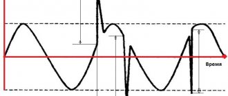
In addition, the output voltage of thyristor stabilizers has a shape other than sinusoidal (trapezoidal or with other distortions, depending on the specific model), which makes their use undesirable to power loads with electric motors (for example, pumps, heating systems).
Conductivity state, dIT/dt
When a triac (thyristor) is in conduction state under the influence of a gate signal, conduction begins in the region of the crystal adjacent to the gate and then quickly spreads to the active region. This delay imposes a limit on the permissible rate of rise of the load current. A high dIT/dt value may cause the device to burn out, resulting in a short circuit between T1 and T2.
When operating in quadrant 3+, the allowed dIT/dt value is further reduced due to the transition structure. This can lead to an instant avalanche process in the gate and burnout during a rapid rise in current. Destruction of the triac may not occur immediately, but with gradual burnout of the Gate-T1 junction, which will lead to a short circuit after several turns on. Sensitive triacs are most susceptible to this. These problems do not apply to Hi-Com triacs, since they do not operate in quadrant 3+.
The dIT/dt value is related to the gate current slew rate (dIG/dt) and the maximum IG value. High dIG/dt and peak IG values (without exceeding the rated gate power) result in a higher dIT/dt value.
The simplest example of a load that produces a high initial inrush current is an incandescent light bulb, which has low resistance when cold. For resistive loads of this type, the dIT/dt value will reach its maximum value when the transition to conduction begins at the peak of the mains voltage. If there is a possibility that the dIT/dt of the triac will be exceeded, this must be limited by placing an inductor or ITC thermistor in series with the load.
The inductor should not saturate during the maximum current peak. To limit the dIT/dt value, a coreless inductor must be used.
There is a better solution with which you can avoid the need to connect current-limiting devices in series with the load. It consists of using the switching mode at zero potential difference. This would give a smooth increase in current from the beginning of the half-wave.
Note: It is important to remember that the zero potential switching mode only applies to resistive loads. Using the same method for reactive loads, where there is a phase shift between voltage and current, can cause unipolar conduction, leading to possible saturation of inductive loads, destructively high current, and overheating. In this case, a more advanced zero current switching method or turn-on phase control circuit is required.
Scheme of operation, advantages and disadvantages of triac stabilizers
Triac voltage stabilizers have an operating principle similar to thyristor devices.
Their obvious advantages, of course, include the above-listed advantages that distinguish thyristor devices:
- speed and accuracy of voltage regulation;
- high efficiency value;
- silent operation (which is especially important when installed in residential areas);
- long-term service life;
- reliability of operation due to the complete absence of mechanical moving parts.
Modern triac voltage stabilizers, like their thyristor analogues, are distinguished by a wide input voltage range and the ability to operate at fairly low temperatures.
Their significant disadvantages are their high cost compared to relay models and stepwise regulation of the output voltage. The disadvantages also include the greater bulkiness of power switches compared to thyristor analogues: one triac occupies an area sufficient to accommodate several thyristors. Of course, this does not have a positive effect on the overall dimensions and weight of the devices.
Comparing the types of semiconductor switches used, we add that triacs are less resistant to current overloads and during operation can heat up much more, which increases the risk of their failure.
Triac stabilizers have the same application restrictions as thyristor ones. They cannot be called a good solution for organizing the protection of electric motors or loads with an electric drive due to the distortion of the output signal shape: as a rule, this is a modified sine wave. Speaking about limitations in use, it is worth adding their low resistance when working with an inductive load.
Attention!
When purchasing a triac stabilizer to power voltage-sensitive electrical devices, it is necessary to clarify the number of power semiconductor switches involved in the stabilizer circuit - the more there are, the more the device will be able to provide an output voltage closer to the rated value.
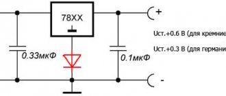
Thyristor open state
The thyristor goes into the open state when a positive bias relative to the cathode is applied to the gate. When the threshold value of the gate voltage VGT is reached (the current through the gate has the value IGT), the thyristor goes into the open state. For a stable transition to the open state with a short control pulse (less than 1 μs), the peak value of the threshold voltage must be increased.
Once the load current reaches the IL value, the thyristor will remain on in the absence of gate current.
It should be noted that the values of the parameters VGT, IGT and IL are specified in the specification for a junction temperature of 25 °C. These values increase as the temperature decreases. Therefore, the external circuits of the thyristor must be designed to maintain the required amplitudes of VGT, IGT and IL at the minimum expected operating temperature.
The sensitive gate of thyristors such as BT150, when the junction temperature increases above Tj max, can cause false operation due to leakage current from the anode to the cathode.
To avoid false positives, the following recommendations can be recommended:
- The operating temperature of the junction must be less than the Tj max value.
- Use lower sensitivity thyristors, such as the BT151, or reduce the sensitivity of an existing thyristor by inserting a 1kΩ or less resistor between gate and cathode.
- If it is not possible to use a less sensitive thyristor, it is necessary to apply a small reverse bias to the gate in the off phase of the thyristor to increase IL. In the negative gate current phase, attention must be paid to reducing the gate power dissipation.
Let's sum it up
Comparing triac and thyristor voltage stabilizers with each other and with other types of devices, we can come to the following conclusions:
- both types of devices have both similar capabilities for voltage stabilization and almost identical disadvantages, one of which is stepwise adjustment and, as a consequence, a non-sinusoidal shape of the output signal;
- these stabilizers cannot protect equipment sensitive to network quality, as well as devices with electric motors;
- both devices are not much superior to relay voltage stabilizers in their operating parameters, but their cost is much higher;
- If thyristor and triac devices break down, repairing their electronic components will cost more than previous generations of voltage stabilizers operating on a similar principle.
Despite the fact that triac and thyristor stabilizers are still quite popular, they are gradually but surely being forced out of the market by a new type of device - inverter voltage stabilizers. Developed in 2015, these devices received the highest technical characteristics, including:
- higher stabilization accuracy (2%);
- continuous regulation of the mains voltage and, as a result, pure sine wave at the output;
- extended range of network input voltage (90-310 V);
- instant response speed;
- universal application.
Some features of Hi-Com triacs
Hi-Com triacs have a different internal structure from conventional triacs. One difference is that the two halves of the thyristor are better isolated from each other, which reduces their mutual influence. This provides the following benefits:
- Increasing the permissible dVCOM/dt value. This makes it possible to control reactive loads (in most cases) without the use of a damping device, without switching failures. This reduces the number of components, PCB size, cost, and eliminates energy dissipation losses from the damping device.
- Increasing the permissible dICOM/dt value. This significantly improves performance at higher frequencies and for non-sinusoidal voltages without the need to limit dICOM/dt using inductance in series with the load.
- Increasing the permissible dVD/dt value. Triacs are very sensitive at high operating temperatures. A high dVD/dt reduces the tendency for spontaneous switching from a non-conducting state to occur at the expense of dV/dt at high temperatures. This allows them to be used at high temperatures to drive resistive loads in kitchen or heating applications where conventional triacs cannot be used.
Due to the special internal structure, operation of Hi-Com triacs in quadrant 3+ is impossible. In most cases this is not a problem since it is the least desirable and least used quadrant. Therefore, replacing a conventional triac with a Hi-Com is almost always possible.
More detailed information on Hi-Com Triacs can be found in Philips specific documentation: “Factsheet 013 - Understanding Hi-Com Triacs” and “Factsheet 014 - Using Hi-Com Triacs”.
Nomenclature and cases
The Philips industrial range of thyristors starts from 0.8 A in SOT54 (TO92) and ends with 25 A in SOT78 (TO220AB).
The Philips industrial range of triacs (triacs) starts with 0.8 A in SOT223 and ends with 25 A in SOT78.
The smallest surface mount triac (thyristor) package is the SOT223 (Fig. 11). The power dissipation depends on the degree of heat dissipation of the printed circuit board on which the device is installed.
The same chip is installed in a non-insulated SOT82 package (Fig. 13). The improved thermal dissipation of this package allows it to be used at higher current ratings and higher power.
In Fig. Figure 12 shows the smallest package for conventional installation - SOT54. The crystal that is equipped with SOT223 is placed in this case.
SOT78 is the most common non-insulated package, most home appliance devices are manufactured using this package (Fig. 14).
In Fig. Figure 15 shows SOT186 (F-frame). This housing allows, under normal conditions, a potential difference of 1500 V between the device and the heat sink.
One of the latest packages is the SOT186A (X-package), shown in Fig. 16. It has several advantages over previous types:
- The package has the same dimensions as the SOT78 package in lead clearances and mounting surface, so it can directly replace the SOT78 without modifications to the installation.
- The case allows, under normal conditions, a potential difference of 2500 V between the device and the heat sink.
Total thermal resistance
It makes sense to carry out all calculations for calculating thermal resistance for an already established regime lasting more than 1 s. For pulsed currents or long transients less than 1 s, the heat removal effect is reduced. The temperature is simply dissipated in the volume of the device with very little heat removal achieved. Under such conditions, the heating of the junction depends on the total thermal resistance “junction - device body” Zth j–mb. Therefore, Zth j–mb decreases with decreasing current pulse duration due to less heating of the crystal. When the duration increases to 1 s, Zth j–mb increases to a value corresponding to the steady state Rth j–mb. The characteristic Zth j–mb is given in the documentation for bidirectional and unidirectional electric current in pulses lasting up to 10 s.