Zero is missing from the socket. Is it possible to extend the wire from the neighboring one?
The headache of any electrician is the loss of zero.
In its absence, all consumers will be without electricity. The neutral wire appears from the midpoint of the windings of a high-voltage transformer connected in a star. This point is routed to all cabinets and panels, and the grounding bus also extends from this point. The neutral wire is most important for the safety of electrical equipment. The alternating voltage in the network has a sinusoidal shape. The three phases are shifted relative to each other by an angle of 120*. This is a bit confusing, so these curves are illustrated here. If you measure the voltage with a standard voltmeter, this value between the phase wire and the neutral wire will be 220 V, but this is the average value for half the period. The tester is not an oscilloscope, but only an average meter. In fact, the instantaneous values of peak voltages are greater than 220 V to the square root of 2. In other words, 220 * 2^0.5 = 311 V.
The voltage sine wave says that the average voltage value is 220 V, the peak value is 311 V. Measurements are taken relative to the zero abscissa axis.
The shape of the curve between the two phases is also a sinusoid. The average line voltage is 380 V, and the peak voltage is 536 V.
From the point of view of the average person, it is not clear why when zero is lost, the voltage in the network should increase. Logic dictates exactly the opposite - a complete loss of voltage. And indeed, if you disconnect the neutral wire to your apartment, the light will go out and nothing bad will happen to the equipment. But here we are talking about a zero break at a substation or at floor-to-floor distribution boards.
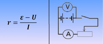
Let's start unwinding the ball from the very beginning - the active energy meter. At first glance, this is a standard device, but there is a pitfall here. The meter has two windings - voltage, connected between phase and zero, and current, included in the phase break. The voltage between points A and B is 220 V, completely dropping across the voltage winding.
If the zero is broken, the phase will flow through the voltage winding and flow to the consumer. If a consumer takes the indicator and pokes it into a socket, he will detect two phases at once, but the voltmeter will show a stable zero. Perhaps this information will make many people’s brains boil, but there is nothing magical here. It's all about the counter.
If the phase breaks, everything is more logical - nothing will be observed anywhere.
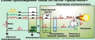
Now about the main thing. When the zero drops to the meters that supply two or more apartments, an interesting process occurs.
Concepts of zero and phase
Electrical energy in a residential building comes from a transformer substation, the main purpose of which is to convert high voltage, most often to 380 V. Electricity is supplied to houses underground or overhead to the input distribution board. Then the voltage is supplied to the panels of each entrance. Only one phase with zero enters the apartment from it, i.e. 220 V and protective conductor (depending on the design of the electrical wiring).
Thus, the conductor that supplies current to the consumer is called phase. Inside the transformer, the windings are connected in a star with a common point (neutral) grounded at the substation. It is connected to the load with a separate wire. The neutral, which is a common conductor, is designed to allow current to flow back to the source of electricity. In addition, the neutral wire equalizes the phase voltage, i.e. value between zero and phase.
Ground, often referred to simply as ground, is not connected to voltage. Its purpose is to protect a person from the effects of electric current at the moment of problems with the consumer, i.e. in case of breakdown on the body. This can occur when the insulation of the conductors is damaged and the damaged area of the device body touches. But since consumers are grounded, when dangerous voltage occurs on the frame, grounding attracts the dangerous potential to the safe ground potential.
Methods for three-wire wiring
In this case, the third wire will be ground. The phase can be easily found with a probe (how to do this was described above). To find zero and ground, you should use a multimeter or tester to determine them.
The procedure should be as follows:
- using a probe, we determine the phase;
- measure the voltage between the phase and the remaining two wires;
- the potential difference between zero and phase will be around 220V, the voltage between ground and phase will be less than this value.
Actually, having a multimeter, you can determine ground, zero and phase without a voltage indicator. We'll tell you how to do this using the M820D model.
Features of determining phase and zero
On a two-wire network
Identification of conductors in a two-wire network is much simpler, since it is carried out in the simplest way; this will require:
- Determine only the phase, since it is known that the second conductor will be zero.
- An indicator screwdriver is ideal for determining the phase in a two-wire network; the detailed procedure was described above.
On a three-wire network
The situation is a little more complicated with modern types of three-wire networks, since they also have grounding.
To determine the purpose of the conductors, you must adhere to the following algorithm of actions:
- The phase is determined using an indicator screwdriver using the method described above. After this, it is recommended to mark it with a marker so as not to mix up the wire in the future.
- To work with zero and ground, you will need to use a multimeter. The neutral conductor may also have voltage, which is caused by phase imbalance, but its readings never exceed 30 V. The multimeter must be switched to operating mode to measure AC voltage, after which one probe is connected to the phase, and the second one in turn to the remaining conductors. Zero will be where the lowest voltage parameter is recorded.
- Sometimes both conductors have the same voltage ratings. In this case, the phase must be isolated and the multimeter switched to a mode designed to determine the resistance level. Also, you will need to select an external grounded element and touch it with one probe of the device, and the second in turn to each of the conductors being tested. In the case when the multimeter shows a resistance of 4 ohms or less, the connection is made to ground; if the reading is higher, then it is zero.
- However, resistance readings are not accurate if the neutral was grounded while still inside the electrical panel. Then you will need to detect and disconnect the grounding element that is connected to the bus. After this, take a test lamp and perform the previously described experiment on connecting it. It lights up only when the neutral conductor is connected.
Determination of zero and phase
In order not to confuse zero and phase on the switch, or when carrying out other electrical work, you need to use special phase-indicating tools or probes. The easiest way is to use an indicator screwdriver.
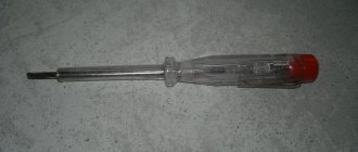
Indicator screwdriver
To know how to determine phase and zero with an indicator screwdriver, you need to understand the principle of its operation. It is configured in such a way that the internal neon lamp lights up when a potential difference appears between the working contact of the screwdriver and the metal terminal at the end of its handle. To correctly indicate the phase with a screwdriver, you need to follow simple steps:
- Turn off the power supply automatically;
- Strip the ends of the tested conductors and separate them to a safe distance;
- Apply power to the electrical network;
- Touch the tip of the probe to the end of the conductor being tested;
- Press the metal terminal at the end of the screwdriver handle with your finger; touching the screwdriver tip during operation is prohibited;
- If the phase is being tested, the light inside the probe should light up.
In addition to the usual indicator, there is a screwdriver for dialing. It differs in that it contains batteries and indicates the phase without touching its opposite metal end with your finger. also an indicator screwdriver with the function of detecting hidden wiring. It can determine where the apartment's electrical network runs inside the wall. It uses a non-contact method of detection by the electromagnetic field arising around the conductor.
To use a screwdriver, you need to remove the cap from it, which will bring it into working condition and place it in the place where the electrical wiring is supposed to be located. When a wire is present in the screwdriver handle, the indicator lamp will light up.
Warning lamp
Another way to determine phase and zero without instruments is to make a test lamp. Such an indicator is created simply: you need to solder wires of sufficient length to the terminals of the socket and screw an incandescent or neon lamp into it. One of the terminals of such a phase detector is connected to the battery, and the second one can check the presence of supply voltage in the network . To do this, touch the test conductor with the stripped end of the wire. If this is a phase, the lamp should flash. This method is very dangerous, so it should be used only in exceptional cases, moreover, it is prohibited by the Rules for the Safe Operation of Electrical Installations.
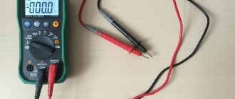
Multimeter measurement
In the absence of an indicator screwdriver and for more accurate measurements of the network supply voltage, a multimeter is used, also called a tester. Using it, you can determine the phase, neutral and ground conductors in a three-wire network. The fact is that an indicator screwdriver can only show large differences in potentials, that is, it only shows the phase. The multimeter works with different signals: high and low levels, positive and negative. Its task is to show the parameters of the electrical circuit.
Read also: Connection diagram for stabilizer 7805
To find out how to find phase and zero with a multimeter, as well as the ground wire, you need to properly configure and connect this measuring device. This is done like this:
- Install the black probe of the multimeter into the socket marked COM, and the red probe into the socket marked U, Ω, Hz;
- Use the knob on the front panel to select the AC current measurement mode, the measurement limit is greater than 220 V.
After setting, you need to simultaneously touch the two ends of the probes to the two terminals being tested. Value on the multimeter screen:
- More than 100 V - phase and zero are found;
- More than 160 V - phase and ground line found;
- Less than 70 V is zero and ground.
By testing all three lines in this way, you can confidently determine where the desired potential is present.
An easier way to determine the phase with a multimeter is to use a probe installed in the U, Ω, Hz hole to touch all ends of the electrical network one by one. In case of contact with the phase conductor, the multimeter will show a voltage of 8 -15 V. In other cases, the readings will be at the level of 0 - 3 volts. Use the multimeter with caution, using insulated shoes and never touch the ends of the probes without insulation with your hands.
When doing any work with electrical wiring, you must follow safety precautions, that is, de-energize the room when installing and repairing electrical equipment, and during the performance test with the circuit breaker turned on, provide yourself with reliable insulation protection.
Carrying out repair work in any room, an important point is to equip this room with electricity. In addition to electrical wiring, do not forget about the need to install sockets and switches, with the help of which the lighting will be controlled. A rather important point here will be to determine the phase, zero and grounding conductor of the system.
For professional installers, this task is very simple, which cannot be said about ordinary people, who are not always able to cope with such a task. However, finding zero and phase is not as complicated a process as it might initially seem, and it includes several determination methods.
It should be understood that the wiring in the apartment usually has a voltage of 220V, since it involves connection to the neutral conductor and to one of the phases. In this case, grounding is mandatory, which makes the electrification of the room safe for the occupants.
How to use the device?
Above, we looked at how to find a phase wire using an indicator screwdriver, but it will not be possible to distinguish between zero and ground using such a tool. Then let's learn how to test the wires with a multimeter.
The preparatory stage looks exactly the same as for working with an indicator screwdriver. When the voltage is turned off, strip the ends of the wires and be sure to separate them so as not to provoke accidental contact and a short circuit. Apply voltage, now all further work will be with a multimeter:
- Select on the device the measuring limit of alternating voltage above 220 V. As a rule, there is a mark with a value of 750 V in the “ACV” mode, set the switch to this position.
- The device has three sockets into which test leads are inserted. Let's find among them the one marked with the letter “V” (that is, for measuring voltage). Insert the dipstick into it.
Touch the probe to the stripped conductors and look at the device screen. If you see a small voltage value (up to 20 V), it means you are touching a phase wire. In the case where there is no reading on the screen, you found zero with a multimeter.
To determine the “ground”, clean a small area on any metal element of home communications (this could be water or heating pipes, radiators).
We have three wires, among them we need to find phase, zero and ground. Touch the stripped area on the pipe or battery with one probe, and touch the conductor with the other. If the screen displays a reading of about 150-220 V, it means you have found a phase wire. For the neutral wire, with similar measurements, the reading fluctuates between 5-10 V; when you touch the ground, nothing will be displayed on the screen.
Mark each core with a marker or electrical tape, and to make sure the measurements taken are correct, now take measurements relative to each other.
Touch the phase and neutral conductors with two probes, a figure within 220 V should appear on the screen. The phase and ground will give a slightly lower reading. And if you touch zero and ground, the screen will show a value from 1 to 10 V.
Non-standard methods: how to determine the phase in the wiring
It should be taken into account that these methods are unsafe. It is recommended to use them only if all necessary safety measures are observed.
Determination methods:
- Homemade control light;
- Potato.
To make a control light, you will need a regular socket, an incandescent lamp of any style and a meter of wire. First of all, we strip the wire of insulation to a length of approximately 1 cm. Next, we disassemble the cartridge and connect the ends of the wire to its terminals.
Then, in order not to damage the light bulb, you need to strip the remaining ends of the wire to a length of 3 cm. Screw the light bulb into the prepared device. After this, turning off the voltage, we strip the ends of the conductor on which we need to find the phase wire.
Next, using any metal object, we clean a small area on the metal surface of the water pipe. We apply voltage to the conductor and touch the stripped area on the pipe with one control contact, and touch one of the wire contacts with the other. When you touch the phase conductor, the light bulb will light up.
Using a potato, check which of the wires is phase, as follows. The device will require two meter-long wires and a 1 mOhm resistor. One of the wires must be mounted into a potato and attached to the pipe. The other wire is mounted into the potato at one end, and the phase wire is searched for at the other. The phase wire will be indicated by the appearance of darkening on the potato.
Probe indicators for searching for phase and zero
A device designed to find zero and phase is called an indicator. Light indicators for determining the phase on neon light bulbs are widely used. Low price, high reliability, long service life. Recently, LED indicators have also appeared. They are more expensive and require additional batteries.
On a neon light bulb
It is a dielectric case, inside of which there is a resistor and a neon light bulb. Touching the electrical wiring wires one by one with the screwdriver end of the indicator, you find the phase by the glow of the neon light bulb. If the light bulb lights up when touched, it means it is a phase wire. If it doesn't light up, it means it's a neutral wire.
Indicator housings come in different shapes and colors, but the filling is the same for all. To prevent an accidental short circuit, I advise you to put a tube made of insulating material on the screwdriver shaft. The indicator should not be used to unscrew or tighten the screws with great force. The indicator body is made of soft plastic, the screwdriver shaft is pressed in shallowly and the body breaks under heavy load.
LED probe indicator
Indicator-probes for determining the phase on LEDs appeared relatively recently and are gaining increasing popularity, as they allow not only to find the phase, but also to ring circuits, check the serviceability of incandescent light bulbs, heating elements of household appliances, switches, network wires and much more. There are models with which you can determine the location of electrical wires in the walls (so as not to damage them when drilling) and, if necessary, find the place of their damage.
The design of the LED probe indicator is the same as on a neon light bulb. Only instead of it, active elements are used (field-effect transistor or microcircuit), an LED and several small-sized DC batteries. The batteries last for several years.
To find the phase, use the LED indicator-probe and its screwdriver end to touch the conductors sequentially, while you cannot touch the metal pad at the end with your hand.
. This area is used only when checking the integrity of electrical circuits. If, when searching for a phase, you touch this pad, the LED will also light when you touch the neutral wire with the indicator!
A brightly lit LED will indicate the presence of a phase. According to the rules, the phase wire should be on the right side of the socket. How to check contacts and circuits with such a probe indicator is described in detail in the instructions supplied with it.
How to make a probe indicator yourself to find phase and zero on a neon light bulb
If necessary, you can make a probe indicator with your own hands to search and determine the phase.
To do this, you need to solder a resistor with a nominal value of 1.5-2 MΩ to one of the terminals of any device, even a starter from a fluorescent lamp, and put an insulating tube on it.
A light bulb with a resistor can be placed in the handle of a screwdriver or the body of a ballpoint pen. Then the appearance of a homemade probe indicator will differ little from the industrial design.
Searching or determining the phase is performed in exactly the same way as with an industrial probe indicator. Holding the light bulb by the base, touch the end of the resistor to the conductor.
When selecting a resistor, sometimes difficulties arise in determining its value if colored rings are applied to the resistor body instead of a number. It will help you cope with this task.
What is phase and zero in electricity for a beginner
In order to grasp the principle of finding phase and zero in a network, you should first determine for yourself what these terms mean, which for the average person may sound like completely incomprehensible concepts. Any system, regardless of its length, consists of three phases, and this also applies to low-voltage lines, the task of which is to power residential buildings.
Between any two phases a linear voltage of 380V occurs. However, the voltage of the household network is 220V, the main task is the appearance of the voltage required for the network. For this purpose, in any network there is a neutral wire, which, in combination with any phase, forms a potential difference of 200V, which will represent the phase voltage.
A zero in an electrical circuit is a conductor that is connected to the ground circuit and is used to create a load from the phase. This phase is connected to the opposite end of the winding on the TP. Thus, in a standard socket, for clarity, one input is taken as a phase, and the second as zero.
In simpler terms, a phase is a wire through which current flows. Through the neutral wire, the current returns back to the source. Depending on the number of phases, the system has several wires. Let's say that in a three-phase circuit there are three phase wires and one return wire, zero.
Color designation.
It is not uncommon for many people to be interested in the question of what color the phase-zero-ground wire is, how to determine which wire is which is often made possible with the help of color distinctions used in electrical engineering. However, this method will only work if the wiring is actually done according to all the rules. The insulation of the neutral wire is usually indicated by blue or cyan; the ground combines two colors at once - green and yellow. According to the rules, the phase wire is designated brown, white or black.
Designation of phase and zero letters
. In addition to color designations, letter markings of wires are also possible. The phase is usually designated by the Latin letter “L” and the neutral wire is usually marked by the letter “N”. In addition, grounding also has its own designation, which is usually designated by the letter “G”.
A handy method for determining phase and zero
To implement this option, we do not need absolutely any additional equipment, only a 1 MΩ resistor and 1 raw potato tuber.
Many people may now have a look of bewilderment on their faces, but this method has been tested many times and it really works.
You will need 2 wires 1 meter long, you can use 1-core copper wire for wiring.
Cut the potato in half, attach one end to a water pipe, and stick the other end into the potato. Now take another wire and stick it into the potato at a distance of 0.5 cm from the 2nd wire. Plug the other end into a socket and wait 2 minutes.
The phase wire will give itself away easily, the starch at the cut will begin to foam. This method is quite simple, so everyone can use it at home. We wish you success!
Why does the indicator light up when you touch the neutral wire?
I have been asked this question many times. One of the reasons is the incorrect use of the LED indicator. How to properly hold the LED probe indicator when searching for a phase is written in the article above.
The second possible reason for this behavior of the indicator is a break in the neutral wire. For example, a circuit breaker installed after the meter on the neutral wire tripped. In old apartments this is not uncommon and is a gross violation of the electrical wiring. It is imperative to remove the machine from the neutral wire or short-circuit its terminals with a jumper.
When the neutral wire breaks, a phase is supplied to it through devices connected to the electrical network, for example, through a switch backlight indicator, a TV in standby mode, any charger, a computer turned off only by the start button and other electrical appliances. The indicator shows this. In this case, the neutral wire can be dangerous and touching it is unacceptable. It is necessary to find and repair a break in the neutral wire, which may also be located in junction boxes.
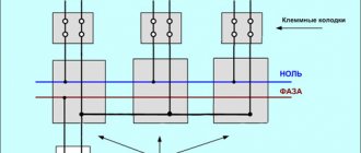
Find the neutral wire in the apartment
According to the rules, the housing of the access panel is grounded. It is carried out using a solid-sized terminal, tightened with a powerful bolt in houses of old construction; it is easier for residents of modern buildings to navigate by the number of cores. The zero bus has the largest number of connections, the phases are separated into apartments (good electricians hang up stickers A, B, C; evil ones don’t). We can easily follow the layout of circuit breakers and meters.
230 volt UK plug
In each case, the common wire will be zero. Color does not play a decisive role. Although according to standards, modern cables are equipped with colored insulation
Please note - if the house is equipped with grounding, there are at least 5 cores at the input. The panel body is placed on a yellow-green
The neutral wire will serve to drain the operating current from the devices (closes the circuit). Merging branches on the consumer side is prohibited. Here are three rules to help you understand the entrance panel (please note, according to the rules, the tenant should not show his nose there at all - we have warned):
- The circuit breaker breaks the phase. There are two-pole models; they are used relatively rarely for rooms with particular danger (bathroom). Therefore, by the position of the wire you can tell: this is a phase. Then it’s worth turning off the machine and ringing the wire on the side of the apartment. It will definitely give the phase position.
- The voltage between the neutral wire and any phase is 230 volts. Based on the key characteristic, we will select a vein that gives the specified difference to another. The spread between phases is 400 volts. The percentage values are 10 percent higher; Russian networks are trying to meet European standards.
- We use current clamps to measure the values on the conductors. A value will appear for each phase, the sum of which (in three) should flow back into the network via zero (or a suitable phase). Grounding is rarely used; the current here is close to zero when the branches are evenly loaded. The place where the value is greatest is traditionally the neutral conductor.
- The grounding terminal of the distribution board is visible. The sign will help you find the neutral wire in houses with NT-CS. In other cases, grounding is supplied here.
Determining the identity of wires without instruments
In order to avoid unpleasant consequences, you need to find out where and which wire is located. An indicator screwdriver is usually used, but if it is not available, the problem can be resolved in other ways.
Most often, the identity of the wires, including phase determination, is established visually by examining the color markings. If the installation of lines was carried out by qualified specialists, they must use the IEC 60446-2004 standard. In accordance with this standard, the neutral wire is marked in blue or cyan, the grounding is yellow-green, and the phase wire is brown or other neutral color. The most important thing is that the color of the phase is completely different from zero and ground. You can examine the markings inside the junction box, as well as at the connection points. If there are no voltage indicator devices, there is an option to check the network using a tester, consisting of a socket with an incandescent lamp and connected wires. The end of one of the conductors is in contact with the metal pipes of the heating system, and the other conductor is in contact with the area being tested. If the light comes on, then there is a phase in that place. This method is considered dangerous, since the likelihood of electrical injury is very high.
The safest way is to determine the phase and zero with an indicator screwdriver, with which you can perform all the necessary checks of the network parameters.
What devices can you use to find out phase or zero?
To find the zero or phase, you can also take precise devices that are not very difficult to operate, but will help to accurately determine in which wires the zero or phase is located.
How to determine phase and zero with an indicator screwdriver
The entire internal structure of this device is assembled into a hollow body made of a material with dielectric properties.
The main part of such a screwdriver is a metal pin, which usually has a flat shape.
To reduce the risk of inadvertent contact with other conductive components in the vicinity of the test line, the exposed portion of the tip is usually small.
Important! During the test, the end of the indicator screwdriver should be in contact. When the need arises, it is capable of performing the simplest task, for example, unscrewing the screws that secure the cover of a socket or switch
But constant use of it as a screwdriver worsens the quality of the test and negatively affects the overall condition of the device.
The metal rod that fits into the tip of the housing becomes a conductor that is connected to the structure inside the screwdriver. This electrical chip consists primarily of a strong resistor with a minimum value of 500,000 ohms. Its main purpose is to reduce the current intensity when connected to the circuit to a value that is safe for the human body.
The next element is a neon based light bulb, which emits current even at low currents. Mutual electrical contact of all circuit components is ensured by a clamping spring. The screwdriver ends with a plug. It screws into the end of the outer shell (this can be all metal or a metal “heel”). In other words, this element acts as a contact pad during the verification process.
When the contact pad of the screwdriver is touched with a finger, it “joins” the circuit. Firstly, the body itself has electrical conductivity, and secondly, it is a powerful “capacitor”. According to this principle, the process of searching for phase and zero occurs.
In the case when the screwdriver's spike is in phase and the circuit is closed, the voltage is enough to generate a current that does not harm the human body by causing the neon to ignite. In the same situation, if the test falls on the zero contact point, no glow will be emitted.
Indicator screwdriver
Multimeter
A multimeter is another test and measurement device that a DIYer needs to master. The price of the device is low (the cost of a fully functional model ranges from 300 to 500 rubles*). Moreover, if such a purchase is possible, it is definitely in demand, since the device is multifunctional.
Multimeter
A multimeter should be one of the elements of the tool “arsenal” of a good owner of a house or apartment.
Important! If the wiring consists of three channels: phase conductor, neutral wire and protective earth channel, but without a color code, or if it is unclear, or if its reliability is unknown, the elimination method can be used
Tester
How to determine the phase using a tester:
- The multimeter is getting ready for use. The black test leads are connected to the COM jack and the red test leads are connected to the voltage jack.
- The operating mode switch is placed on the section designated for AC voltage measurements (~V or ACV) and the needle will be set to a value that is greater than the mains value. In another variation it could be, for example, 500, 600 or 750 volts.
- Next, the voltage is measured between the stripped conductors. In this case there can be three combinations. The first is that between phase and zero the voltage should be close to the standard voltage of 220 volts. The second is that there can be the same voltage between phase and ground. However, it is true that if the line is equipped with a current leakage protection system (residual current protective device - RCD), this protection can work properly. If there is no RCD or the leakage current is small, the voltage remains within the rated range. Third - there should be no voltage between zero and ground
This is only the last option to show that the wire that does not include the measurement is phase.
Important! After checking, the voltage must be turned off and the bare end of the wire must be insulated and marked. For example, you can stick a white tape and make an appropriate inscription on it
Determining phase with a multimeter
How to find phase and zero using an electrician's test
Electrician checking an incandescent light bulb
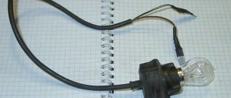
To check the presence of supply voltage in the electrical network, electricians previously used a homemade tester, which was a low-power incandescent light bulb screwed into an electric socket. Two conductors of stranded wire about 50 cm long are connected to the cartridge.
In order to check the presence of voltage, you need to touch the electrical wiring wires with the test conductors. If the light comes on, there is voltage.
Electrician's control on LED
An electrician's inspection of a light bulb requires careful handling and takes up a lot of space. It is much more convenient to do an electrician check on the LED according to the diagram below.
The circuit is simple; a current-limiting resistor is connected in series with any LED. LED of any type and color. Use it in the same way as an electrician's control on a light bulb.
The LED and resistor can be placed in a ballpoint pen housing of a suitable size. In the photo there is a control for the motorist. The control scheme is the same. Only depending on the type of LED used, resistor R1 is set to a value of about 1 kOhm.
It’s easy to check the presence of voltage on the wires in the car’s on-board network using such a tester; the right end is connected to ground according to the diagram, and the left end touches any contact. If there is voltage at the contact, the LED will light up. If you touch the positive terminal of the battery with one end of the fuse, and touch the other with the control, then if the LED does not light, it means the fuse is broken. This way you can check both incandescent light bulbs and the presence of contact in the switches.
Phase search in the presence of neutral and ground conductors
If you need to find a phase in an electrical wiring that has phase, neutral and ground wires, then using a tester this is easy to do. It is enough to make three touches with the control wires. You need to assign a conditional number to each wire, for example 1, 2 and 3 and in turn touch the pairs of wires 1 - 2, 2 - 3, 3 - 1.
The following behavior of the light bulb is possible. If when you touch 1 - 2 the light does not light up, it means the wire is 3-phase. If it lights up when you touch 2 - 3 and 3 - 1, it means 3 phase. The meaning is simple: when you touch the neutral and grounding conductors, the light will not shine, since practically these are conductors connected together on the shield.
Instead of testing, you can turn on any AC voltmeter designed to measure a voltage of at least 300 V. If you touch the phase wire with one probe of the voltmeter and the neutral or ground wire with the other, the voltmeter will show the voltage of the supply network.
Search for phase and zero using a control
Attention, touching any exposed conductors while searching for a phase with a tester may result in electric shock. Everything is done very simply, one end of the control wire is connected to a central heating or water supply pipe stripped to metal, and the other end in turn touches the wires or electrical wiring contacts
When you touch the phase wire, the light bulb will light up
Everything is done very simply, one end of the control wire is connected to a central heating or water supply pipe stripped to metal, and the other end is touched in turn to the wires or electrical wiring contacts. When you touch the phase wire, the light bulb will light up.
If you cannot reach the metal of the pipe, you can use water flowing from the mixer. To do this, turn on the water and place one control wire under running water as close to the mixer as possible. Touch the other end of the wire to the electrical wiring. The weak light of the light bulb will tell you where the phase is.
It is best to screw in the lowest-power light bulb into the control; I used a 7.5 W refrigerator light bulb. In order to reach the water, you can use a piece of any wire or a standard extension cord.
Rules for using a multimeter
To determine phase and zero using a multimeter, it is necessary to clean the ends of the wires from insulation, separate them in different directions to avoid contact, which will cause a short circuit, and then apply electrical voltage.
On the multimeter, set the measuring limit of alternating voltage above 220 V. Insert a voltage probe into the socket marked “V”. Touch it to the cleaned core and watch the display. If the value is up to 20V, this is a phase wire; if there is no reading at all, this is zero.
To use the multimeter correctly, the following rules must be observed:
- It is contraindicated to use the device in high humidity.
- Do not use damaged test leads.
- It is prohibited to measure parameters with a value exceeding the upper limit of the measuring device.
- During the measurement procedure, you cannot turn the switch and change the limits.
Types of voltage indicators: single-pole and double-pole devices
Modern industry produces a large number of different indicators. There is no specific standard classification for them. According to the characteristics of the technical device, devices can be divided into single-pole and double-pole, and they also distinguish between passive and active products. This section will discuss classification based on the first criterion.
Single-pole indicators. This type includes the simplest devices, the design diagram of which is described above: based on a tip and a neon lamp for indication. More advanced single-pole devices have an LED lamp, battery power, and an audible signal - in addition to the glow of the lamp. According to the principle of operation, such indicators are identical to the simplest devices, but it becomes possible to test the wires.
The most advanced single-pole models have a complex structure, although the principle of operation remains the same. In addition to the functions already listed, they have the ability to detect the break of hidden wires located under a layer of plaster.
The two-pole type of indicator screwdrivers is distinguished by the fact that it has not one, but two bodies. Each is made of dielectric material and has a backlight - neon or LED lamp. Some devices are equipped with a sound signal. The two housings are connected by a wire, the length of which usually does not exceed 1 m, and both have a sting. Such devices are considered professional and are used to check the presence of current between two contacts. Among the bipolar ones, there are models that determine not only the presence of voltage, but also its magnitude.
The two-pole type of indicator screwdrivers is characterized by the presence of two bodies
Passive voltage and current indicators: operating features
The second sign of the classification of indicators is their division into active and passive devices. The basis is the functional features of the tools. Passive devices include those with the following characteristics:
- Not complicated. Single-pole, consist of one housing with elements placed in it.
- Limited functionality. The only thing that an indicator screwdriver of this type shows is whether there is voltage at a certain point in the electrical circuit.
- Unprofessional tool. Most often used in everyday life, it is unacceptable for electricians due to the lack of opportunities to provide the necessary inspection of the condition of electrically conductive cables.
The advantage of these indicators is that when determining the presence of voltage, a zero is not needed; its role is performed by a person holding an indicator screwdriver in his hands. The peculiarity of its device is also that the resistor, due to its significant resistance, does not detect the presence of voltage below 50 volts.
It is not difficult to understand how to find a phase with an indicator screwdriver of this type. You should touch the conductor with the sting, and press the plate on the device body with your hand. If there is voltage, the neon light will light up.
Passive voltage and current indicators determine only whether there is voltage at a certain point in the electrical circuit
Characteristics of active voltage indicator screwdrivers
Active indicators have a more complex structure. Inside the case there is a circuit that functions slightly differently than passive devices. This device is more sensitive. The LED voltage indicator reacts not only to the presence of current, but also to the electromagnetic field that necessarily forms around the conductor.
Active indicators have the following technical characteristics:
- Having your own power source. There is a battery inside the case that powers the internal device.
- LED instead of neon lamp.
How to use an LED indicator screwdriver? If you hold the tip with one hand and touch the plate on the body with the other, the LED lamp will react and light up. This functionality is actively used when testing wires.
Active indicators have their own power supply