How to measure voltage with a multimeter
Almost each of us, sooner or later, has (or will still have to) face the task of measuring electrical voltage.
You may need this in one of an infinite number of everyday situations, and it would be good to know in advance how and with what help this can be done. To measure voltage, you only need one device called a multimeter and a source of electricity. Measuring the voltage of a lying battery, a laptop power supply, or exposed wires in an apartment are some of the most common uses.
In this article, we will look at an example of how to measure the voltage of electrical energy using a household multimeter.
As an example of why everyone needs to know this, we can cite several everyday situations: by measuring the voltage on a battery, you can understand how “healthy” it is, or maybe it can already be thrown away; the lamp in the chandelier does not light, although the light bulb is new - it’s worth checking, there may be a problem in the wiring; When there is a power outage, it is a good idea to check on the panel in the entrance whether you have actually cut off the power to the entire apartment. In general, there are a lot of applications.
We have dealt with the tasks, now it’s worth talking about what you will need for measurements. In 99% of everyday situations, you will only need an AC or DC source and a “multimeter” - a device that measures voltage, also called a “tester”, and other electrical indicators, and specifically one of its functions is a voltmeter . For home measurements, the simplest model is suitable, which can be found in the store at a price of 200 rubles.
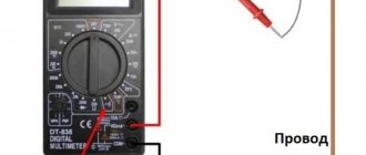
And just a little about the current. Electrical voltage is measured in volts (V) . The current itself can be direct (DCV) or alternating (ACV) . In outlets and home wiring, the current is always alternating, but in everything that has “+” and “-” (batteries, accumulators, etc.) it is constant. First of all, determine what current you are going to measure and select the appropriate switch position on the multimeter: DCV - direct current, ACV - alternating current.
The digital values on the multimeter are the maximum values measured. If you don't even know approximately what voltage you need to measure, start by setting it to the highest value.
It is worth considering that many modern multimeters can themselves determine what current is supplied to them - direct or alternating. If your multimeter is one of these, then instead of the DCV and ACV switch positions you will have one position - V. In this case, just set it.
How to determine phase and zero with an indicator screwdriver. Technology
In fact, everything is very simple! You need to know how to determine the phase and zero with an indicator screwdriver on a wire coming out of a wall, ceiling, outlet or switch. If this is a phase, the wire is dangerous and should not be touched with your hands.
For these purposes, man invented a wonderful device - an electrical probe. It looks like an ordinary screwdriver, but with an indicator. In the store you can easily buy such a screwdriver for around 50 rubles. The only point is that you need to look for a probe for 220V, and not 12/24V.
So, in front of us is a wall with an unknown wire coming out of it. What are we doing?
- We take the sampler in the right hand (for left-handed people - in the left):
- At the end of the plastic probe handle you can see a metal base (plate). We touch it firmly with our thumb, as shown in the figure:
- With the remaining 4 fingers, we do not completely close the probe handle, since there is a light bulb inside that you will have to observe. At the same time, make sure that your hand does not touch the metal part of the probe opposite the handle. That is, as if you were holding the screwdriver completely only by the plastic handle in one hand:
- We bring the probe to the exposed part of the wire and touch it with the metal end of a screwdriver. If the light comes on, then this wire is live. He poses a real danger! This is the “Phase”:
- We bring the probe to the bare end of the other wire. If the light does not light up, it means there is a safe wire in front of you. This is “Zero”:
In the future, you will overcome the psychological barrier and will be able to calmly pick up the wire on which the light bulb does not light up. But now you don’t need to do this - just fix it for yourself - this wire is safe.
Multimeters, testers and their varieties
A multimeter, also known as a multitester, is a special device for measuring a wide variety of characteristics and parameters of the electrical network, as well as the parts and elements powered by it.
The device is designed so that at a construction or repair site it is possible to determine with high accuracy:
- constant and alternating voltage;
- alternating and direct current;
- resistance, capacitance and much more.
In addition to the above parameters, multimeters are equipped with additional measurement functions, which also allows you to test transistors, “ring” the electrical cable to the junction box and the wires coming out of it, check the performance of diodes, etc.
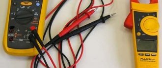
There are two main types of metric instruments: analog and digital. These devices differ in functionality, measurement accuracy, build quality, and packaging. In any case, these are very useful measuring systems for everyone.
In an analog multitester, the measurement result is displayed using a regular arrow on the scale. Sometimes the operation of such an analog device is not entirely appropriate - it is difficult for a beginner or non-expert in the field of electrical engineering to understand all the scales, the “division value” of a certain parameter, and calculate the final value of the electrical characteristic.
And yet, the analog tester does not have a fixed pointer in position, which makes it difficult to read the result and generally work with the device.
A digital multimeter displays measurement results as digital values on an LCD screen. It ensures extreme ease of operation of the device, eliminates any errors associated with taking readings and calculating the required parameter, taking into account the “division value” of the scale. This is one of the main reasons for the popularity of digital multitesters among craftsmen.
Standard multimeters can cost more than $5. But one thing always remains the same - the rotary trigger occupies the central place on the panel. The location of the remaining controls in the corners of the panel, the presence of the necessary connectors at the bottom of the panel, and multi-colored symbols do not change.
If you purchase such a product, be sure to buy it with an external silicone cover, which protects against dust, moisture, falls from a small height, has special clamps and a stand, which can be very useful in the most unexpected situations of using the multitester.
Checking electrical circuit parameters
When testing electrical circuits, you can test many of their parameters. This includes current, network voltage, and signal frequency. But to determine serviceability, you only need to ring the circuit for integrity and check the insulation resistance. Both can be done with a multimeter.
Read also: Switch designation on the GOST diagram
In order to know how to test electrical wiring with a multimeter, you need to correctly configure the measuring device and correctly perform the measurement steps. To check the integrity of the wire you need:
- Connect the black probe of the multimeter to the socket labeled COM, and the red one to the socket labeled U, Ω, Hz;
- The meter knob must be set to the 20 Ohm position;
- Connect the measuring contacts to both ends of the wire. If the ends are in different places in the room, you need to use a previously tested extension wire;
- The tester screen will display the value. If the value does not exceed 2 ohms, it means that the integrity of the wire is not compromised. If the readings are not at the same level or more than 8-10 ohms, then there is a break in the circuit.
In the same way, wires in a car and cables of various electronic devices are tested.
In addition to checking integrity, wires are tested for insulation resistance. This can also be done with a multimeter:
- The probes remain in the same holes as when checking integrity;
- The measurement mode selected is the same - resistance test;
- The measurement limit must be selected as large as 20 or 200 megaohms;
- Touch the probes to opposite conductors of the cable: phase and neutral or phase and screen. In a car, this is ground and signal wire;
- The screen should remain displaying infinity; if there is any value instead, it means there is a short circuit somewhere. Changing values indicate interference in the network.
In addition to ordinary wires, there are high-voltage wires that can withstand high current and voltage loads. These include spark plug wires in cars. The current that is required when starting the engine flows through them; this current reaches 80-150 amperes. Knowing how to test high-voltage wires with a multimeter is required when diagnosing car electronics. The ringing of these wires occurs according to the indicated diagram , with the difference that it is necessary to set a larger resistance measurement limit. Typically this limit should be set at 20 kilo-ohms.
After this, you need to find the ends of the wire and connect the multimeter probes to them. The resistance of this wire will be displayed on the device screen. It should be in the range from 1 to 10 kOhm.
In trucks, as well as in networks located in places subject to constant mechanical stress, conductors with a screen - armor or armored wires - are placed. The only special feature of the armored wire is the screen, made of durable metal. You can check the integrity and insulation of the armored wire in the same way as a regular one, you only need to have access to its ends and the screen outlet.
Determination using a multimeter
Any home electrician should have a multimeter in their toolbox. This is a universal tester that allows you to check the performance of electronic components, measure voltage and current, and also test circuits. An inexpensive and high-quality device with simple functionality can be purchased for 300-500 rubles. Professional electricians use more expensive devices with additional options and minimal error.
There are two types of multimeters based on the way they work - electronic and analog. Pointer or analogue is a simple device with an arrow. A digital multitester displays values in numbers. The determination method is the same for both types of devices.
Rules for working with a multimeter:
- Measurements cannot be taken at high humidity.
- Defective probes are not used.
- The measurement limit must exceed the measured value.
- When taking measurements, it is forbidden to turn the knobs or set other limits.
Currently, digital multimeters are actively used. The verification algorithm may differ.
Wiring of three wires without markings
You can choose the exclusion method. To find the phase, the multimeter should be assembled and the probes should be placed on the left and right - black in the COM connector, red in the voltage measurement connector. The switch should be placed in the AC voltage sector V
or ACV. The arrow selects the voltage limit - it must exceed the network voltage. On the tester you can see values of 500, 600, 750 W depending on the model.
Then voltage measurements are taken between the stripped conductors. There may be 3 options:
- Between zero and phase there should be a voltage close to the mains 220 V.
- There can also be 220 V between the phase and the ground. If the line is protected by an RCD system, the machine may trip. If there is no RCD or there is a minimum leakage current, the displayed voltage will be within the nominal error.
- There is zero voltage between zero and ground.
After the measurements are completed, the tester is turned off, the ends of the conductor are insulated and marked. It can be done using colored tape or adhesive tape with appropriate inscriptions.
Checking the contact in the socket by directly measuring the voltage
The multimeter is prepared and a control measurement of the voltage in the socket is made. This allows you to verify that there are no breaks in the line and that the device itself is working. If the numbers shown on the display are correct, the connection is correct.
The red probe needs to touch the conductor being tested. When checking the socket, the probe is placed in the socket. If you are testing the stripped end of the cable, it is recommended to connect via an alligator clip. The second probe touches the fingers. Readings are taken on the display. If the black probe is set to zero, the voltage will be zero or close to zero. When it hits a phase, the voltage will reach tens or hundreds of volts.
Touching the probe with your hand is safe in this measurement. The device was previously tested for serviceability, so a person will not be shocked by an electric shock that is life-threatening. But even despite the safety of the procedure, not everyone can cross the psychological barrier. Then you can touch the plaster, ceiling or wallpaper with the probe. They have little moisture, so the readings on the tester will be visible. They will be lower than the required value, but it is realistic to determine the phase in this way. You can also use any grounded device (heating radiator, water supply) or a metal frame without grounding as the second contact.
Search for zero and ground
Determining the phase is not difficult. It is more difficult to distinguish zero from ground. There are different determination methods, but they are all unreliable. You can accurately determine the purpose of the core using professional instruments from the arsenal of specialists.
One way is to check with a multimeter. If the RCD is triggered, it can be judged that the tester was connected between phase and ground. Upon contact with the phase and neutral conductors, the protective device does not operate. This is due to the fact that when measuring between the phase and grounding conductors, a small leakage current is formed, which may not be enough to trigger the protective system.
The second method is calling using a multitester. The multimeter switches to the resistance measurement state. The range can be set to 200 Ohms. Be sure to turn off the voltage on the panel. After this, you should check the voltage between the conductors and the grounded object. The resistance value on the grounding conductor should be lower than on the zero one.
The described methods are approximate and do not provide a 100% guarantee of the correct determination of zero and ground. Connections may be different, and the difference in measurements in all cases is minimal. If necessary, special determination devices should be used.
Setting up and preparing the multimeter
To use the multimeter correctly, you need to configure it. This means that you need to select the value to be measured and the limit of its operation, that is, the value beyond which it will not go.
Symbols on the front panel of the meter
A multimeter can be used to check various electrical quantities: current, voltage, resistance, frequency. It is also used to test the performance of various radio elements: resistors, capacitors, diodes and transistors. The very part of the word “multiple” implies the presence of several types of measurements. To select these types, there is a knob on the front panel of the tester, by turning which you can select the required value.
There is a higher class type of multimeter, for example, Agilent, in which the selection of measurement values is made not with a rotary knob, but with buttons. To select a value, simply click on the button corresponding to this value.
In most cases, the symbols depicted on the body of the multimeter represent designations of electrical quantities accepted in physics or conventional graphic designations of radioelements intended for testing . On the front panel you can find the following symbols:
- U - voltage symbol;
- V - stands for volts, this is also a measure of voltage;
- I is the current; when you set the knob to this designation, the current strength will be measured;
- A - amperes, a measure of current strength;
- Ω, R - symbol of resistance;
- Ohm is a measure of resistance, Ohms;
- -| |- - this icon indicates a capacitor, the multimeter will measure its capacitance;
- Diodes and transistors are also marked on the tester body with their symbols.
But not only the measured values are indicated on the front panel of the tester: the holes for connecting the probes also have their own designations. One of the meter slots will always be occupied by the black probe. This is a common hole, it is usually marked with the inscription COM, which means “common”. In addition to it, the multimeter has two or three working holes, designed respectively for measuring voltage, low current and high current.
The socket marked U, Ω, Hz is intended for measuring resistance, voltage and frequency, as well as for testing various radio elements. You also need to install a probe here to test wires and cables for breaks.
The hole marked mA (mA) is used to test low currents (up to 1 ampere), and the hole marked A (10 A) is needed to measure high amperages.
Also next to the voltage and current icons there are symbols
or -. This indicates the nature of the measured quantity: direct or alternating current or voltage.
Limits of measured values
In addition to designations of the values of the parameters being tested, designations of measurement limits are printed on the front panel of the multimeter. In more advanced equipment, these inscriptions are not present, since the tester electronics itself selects the limit based on the signal supplied to it at the input. However, most multimeters require manual adjustment of measurement limits.
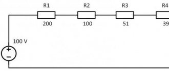
Typically, limits are given by numbers that are multiples of 2: 2, 20, 200... Thus, when choosing a limit, you should be guided by the rule: choose a limit higher than the one being measured, but of the same order. For example, to measure the voltage in a home electrical network (in an outlet), you need to select the AC voltage measurement mode and the measurement limit of 2000 volts. And to test the wires with a multimeter, you need to select the resistance mode and the minimum measurement limit of 2 ohms. However, long cables require a higher measurement limit of 20 ohms. Additionally, you can turn on the button with a sound signal that sounds when a short circuit occurs (circuit presence).
Connecting the tester
To check the parameters of electrical circuits and the continuity of wires and cables with a multimeter, you must correctly connect the meter to the circuit being tested. When checking for circuit integrity, the required area between the meter leads is checked. Therefore, the tester is connected to the terminals of the circuit. If voltage is being measured, the multimeter must be connected in parallel to the section where the voltage is being tested.
When measuring current, the multimeter must be connected in series to the open circuit of the circuit being tested, for example, between the power supply terminal and the load terminal.
Checking devices
Checking the tachometer
To test a new tachometer, you need to connect the multimeter to the terminal on the back of the device and ground. When current is applied to the device, the multimeter will record readings. This technique can be used for any device.
Many devices operate on current that passes through a voltage stabilizer. If several instruments display incorrect readings at once, the stabilizer may be faulty. To check, you need to connect a multimeter to the output connector and turn on the ignition.
Stabilizer check
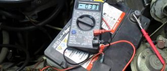
In modern cars, some devices are powered by a voltage stabilizer. If the stabilizer breaks, the instrument readings are distorted. Before checking each device, you need to check the stabilizer itself by connecting a multimeter to its output connector and ground.
The multimeter should show approximately 10V, small deviations are due to the action of the rheostat. A strong deviation indicates that the multimeter needs to be replaced.
Voltage measuring instruments
Indicators or pointers by their action indicate the presence of a certain voltage level in the area being tested. They are not intended to determine its magnitude.
The measurement function is assigned to instruments that are endowed with certain metrological characteristics - voltmeters.
The principle of their operation is based on the use of a measuring head, sensitive to very small currents of the order of microamperes. It is connected to the controlled voltage circuit by terminals through a current-limiting resistor. For devices with several measurement limits, a resistor value switch is installed. Thus, by creating a series chain of certain resistors, switched to the measuring head, the voltmeter measurement mode is selected, creating the same limit for the needle deflection.
For digital instruments, the functions of the measuring head are assigned to measuring, logical and information organs.
To perform such work, it is recommended that a home craftsman purchase a combined device that has the functions of measuring voltage, current, and resistance.
Of the older models produced in the USSR, the Ts4324 tester works well. Half-worn from long-term use, the quality mark applied to the case still lives up to its purpose.
Of course, such pointer instruments in modern times are considered an anachronism. They require attention, knowledge, the ability to make switches and do quick mental math. And errors in the position of the toggle switches during measurements result in burnout of the internal elements of the circuit.
Previously, we had to rescue comrades who had burned their devices through carelessness and help them with repairs.
Since then, the schemes of Soviet testers have remained. If anyone needs them, write in the comments, I’ll send you photos of the required pages by email.
Modern meters of electrical parameters are called avometers, ampere-voltmeters or multimeters.
Their essence is the same: based on an electronic or microprocessor circuit, precise measurements are performed, sometimes almost automatically, with instantaneous display of information in text form on the display.
However, the switches and buttons remain, they must be used intelligently.
How to check high voltage wires
Finding high-voltage wires under the hood is not difficult, and diagnosing them is not fraught with any difficulties. There are three ways to check high-voltage wires, each of which allows you to determine whether there is a breakdown in them.
Visual diagnostics
The easiest way to check spark plug wires for insulation damage is to visually inspect them. It is necessary to carefully check that there are no cracks, cuts or severe abrasions across the insulation area.
Another way to visually check spark plug wires is to observe their operation at night. It is necessary to open the hood of the car at night, start the engine, turn off the headlights and watch the high-voltage wires. If they have strong insulation breakdowns, in the dark the “crickets” will be visible to the naked eye.
Wire check
To check the spark plug wires, an ordinary wire with stripped ends on both sides can be used. In the dark, with the engine running, it is necessary to short-circuit one part of the wire to ground (the car body), and run the other part along high-voltage wires in search of a place where the stripped tip will begin to produce a spark. It is important to check not only the insulating material around the conductor, but also the plastic caps.
Diagnostics with a multimeter
A multimeter in automotive diagnostics is most often used as a voltmeter, but it also has another useful function - the ability to measure resistance. To take measurements, you must completely remove the high-voltage wires (or disconnect one wire on both sides). Next, with the probes of the device set to ohmmeter mode, you should touch both sides of the wire, as a result of which the multimeter will display information about the resistance.
The resistance of serviceable high-voltage wires is up to 10 kOhm. At the same time, it can vary practically from zero. This depends on the type of wires themselves, the insulation used in them, the length, the presence of microdamages, and so on.
How to check wiring in a car with a multimeter
Car electrical equipment malfunctions are divided into electrical appliance malfunctions and electrical wiring malfunctions. How to check this or that device is described in some detail on the website, but how to find faulty wiring was mentioned only in passing. Now I want to try to correct this omission. To troubleshoot, you must be able to read diagrams and have a test lamp on hand. In some cases, a multimeter or ohmmeter may be required.