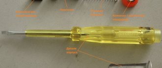
How to use a current clamp?
These devices are very easy to use.
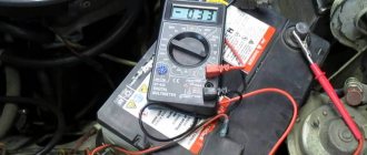
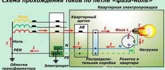
The design of current clamps allows measurements to be taken on an existing electrical installation without any additional installation work and without breaking the power supply circuit. This is their huge advantage. To measure, you need to set the switch to the desired position, wrap the pliers around the wire and record the current readings. The main difficulty in such measurements is to isolate a separate single conductor. If you grab the entire wire (phase and neutral conductors) with pliers, you will get the sum of the currents flowing through both wires. Ideally, zero should be displayed here, since the currents flowing through the phase and neutral conductors are equal in magnitude, but opposite in direction. As shown in the photo below, you will not learn anything and you cannot measure current this way. Although if in this position the clamps show any current value other than zero, this will mean that there is a leak in this circuit equal to the obtained value.
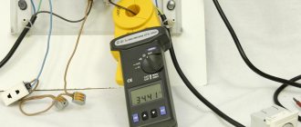
Therefore, it is necessary to find a place where these conductors are separated, and where there is an opportunity to crawl with pincers. For example, in a distribution panel at the point where the phase is connected to the circuit breaker. Unfortunately, this cannot be done everywhere. This is their slight disadvantage, but the ability to measure without breaking the circuit completely overcomes it, at least in my work.
I work in communication rooms where it is strictly forbidden to de-energize communication equipment, so current clamps are the only device that can measure current and calculate the consumed load.
How they work and what types there are, read the article: What are current clamps and why are they needed?
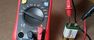
The instructions below are based on the Fluke 302+ model. These are high quality and good clamp meters, but they can only measure AC current. Direct current is measured by other models of clamps in the same way as alternating current, only it is necessary to switch them to the direct current measurement mode.
Before any measurements, make sure that your clamp meter model can be used for this purpose. They indicate the maximum current value that can be measured with them. In my case it is alternating current up to 400A. Although you will not find such high currents at home and therefore any model will be suitable at home.
The safety category is also indicated on the measuring instruments themselves. In my case, the Fluke 302+ model is marked:
- CAT III 600 V - this means that the device is protected from short-term voltage surges within the equipment when used as part of stationary systems with voltages up to 600 V, such as distribution panels, feeders and branches, as well as lighting systems in large buildings.
- CAT IV 300 V - this means that the device is protected from short-term power surges from primary power supply equipment with voltages up to 300V, such as an electric meter, overhead or underground utility system installation.
Instructions on how to use clamp meters
- We find a place where you can freely grab a single conductor with pliers.
- We move the knob for switching measurement modes to the desired position. On AC power, point to A~ or AAC. In a DC network, point to the A- or ADC indicator. These designations are additionally duplicated on the display. Let me remind you that my clamps do not support the DC current measurement function and therefore do not have this designation on them.
- Press the button to open the ticks.
- We grasp the desired conductor and install the pliers perpendicular to the plane of the wire.
- Release the pliers release button. This closes the magnetic circuit and the current is measured.
- We record the resulting current value on the display. If it is hard to see, you can record the measurement results by pressing the “Hold” button. Then you can remove the clamps and see the measured current value. It will remain on the screen until you press the “Hold” button again.
Above I described the main functions of current clamps, i.e. current measurement without breaking the circuit. I think everything is clear.
To ensure the versatility of this device, almost all manufacturers add additional functions to its design. This is the ability to measure other parameters such as voltage, resistance, etc. I will talk about this in the next article: “Additional functions of current clamp meters.”
Today we miss smiles so much:
The principle of operation of current clamps in electrical circuits
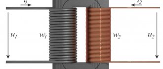
A distinctive feature of clamps is that they function in circuits in the same way as single-turn transformers. Their first winding is the wire that needed to be analyzed, but the secondary winding is located on the device. It is to this that the ammeter is connected, giving the user the opportunity to obtain one or another value.
To determine the measurement value in the initial chain, you should immediately find out its maximum level in the secondary type of winding. In this case, the transformation coefficient is taken into account.
After the magnetic core is connected to the network being measured, a magnetic field with alternating current appears in it. It is he who induces EMF in the secondary winding. The current that appears in this place is measured with a cabinet ammeter. Its value is then displayed on the screen.
Varieties
Several instrument classifications are due to the abundance of parameters for comparison. Since current clamps are used to work in high-power circuits with high voltage, the main division is based on safety requirements.
The division is as follows:
One-handed electrical clamps, designed for work in circuits with operating voltages up to 1000 V. The tool is equipped with a key designed to move apart parts of the magnetic circuit of the current transformer. The device is designed to be operated with one hand and is lightweight and small in size. The device's protection class corresponds to operating voltages up to 1000 V;
Two-handed electrical clamps. This tool provides operation in AC and DC voltage circuits ranging from 2000 V to 10 kV. It has large dimensions due to powerful insulation and is designed to be used with two hands, since the magnetic circuit control handles are long.
Both varieties may have a different display system for the measured parameter:
- Analog (arrow) measuring clamps. The oldest variety, which has not lost its relevance today, thanks to a number of advantages: low inertia of the pointer indicator, which allows you to control and measure short bursts of current, the absence of additional power for the internal circuit. There are also disadvantages, and they are significant: sensitivity to shaking and shock, the need to correlate the readings of the dial indicator and the scale factor of the measurement limit switch;
- Digital electrical clamp meters. The main advantage is that the indicator displays the real value of the measured parameter, relieving the user of the need to convert values. The measurement limit switch only adjusts the indicator readings for greater ease of reading. The biggest disadvantage of digital indicators is their dependence on the power source, since they contain a complex electronic circuit on a digital microcontroller inside. The delay in the settling time does not allow the parameters of short pulses to be measured. Inexpensive models are characterized by poor protection from electromagnetic fields, which leads to measurement errors.
Work in electrical circuits is not limited to just measuring current; other electrical parameters of the network are also important, which is why a whole class of combined tools based on current clamps has emerged:
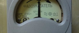
Phase meters. Serve to determine the phasing of wires in multiphase circuits; Wattmeters. Instruments that measure power consumption; Voltmeters. Instruments for measuring voltage values on circuit elements; Megaohmmeters
Devices for monitoring insulation resistance, which is especially important in high voltage circuits.
The presence of a combined instrument does not reduce its reliability, since only the display device remains unified, and additional input terminals and circuit elements are used to measure additional parameters. On the other hand, a clamp multimeter significantly improves ease of use and eliminates the need to carry a set of various measuring instruments.
Types of current clamps: determining which is better
Current clamps are available in different types. The most popular are digital models, but pointer devices are also found. We will find out further what features these tools have.
- Pointer - they are also called analog, since a pointer is used as a display. The design of pointer current meters uses a single-turn transformer, to the terminals of which an ammeter is connected. Models of this type are now practically not found on sale, since they are outdated modifications. The advantage of such devices is the possibility of visual control of the measuring process. The high sensitivity of the pointer pointer to mechanical vibrations leads to distorted results, therefore, to prevent obtaining incorrect values, it is necessary to firmly fix the device. The disadvantage of analog instruments is the need to recalculate the results obtained by multiplying them by the conversion factor.
- Digital - they differ from pointer ones not only in the presence of an LCD display, but also in the absence of the need for recalculation. The display shows ready-made results. Most models have a built-in function for displaying not only current, but also power. The device contains an Ohm's law algorithm, which performs automatic calculations.
- High-voltage - classic clamp meters are designed to measure current in circuits with voltages up to 1000 Volts. However, specialists also use devices for working in networks with voltages above 1000V. Such pliers are called high-voltage, and they differ from standard ones in that they consist of elongated handles with improved insulation. This design eliminates the need for the operator to get close to high-voltage wires. In addition, such devices are designed to operate only in circuits with alternating voltage.
It should be noted that high-voltage devices are classified into types according to the number of handles. They are:
- one-handed - have one well-insulated handle with a lever for opening the magnetic circuit (designed to work with electrical installations with voltages up to 1 kV), and their main advantage is the ability to use one hand;
- two-handed - usually such installations allow you to work in networks with voltages from 2 to 10 kV. The size of the insulated part is 38 cm, and the handles are 13 cm. They must be used with both hands.
This is interesting! Many clamp meters have a key called DATA HOLD. Many people are interested in what it is for and what tasks it performs. Its purpose is to record the readings taken. For example, you managed to place a wire inside the clamp, but the device readings are not visible. To fix them, just such a key is used.
Operating principle
What are clamp meters used for?
They are a type of electrical tester with wide jaws that can pinch the electrical conductor. They were originally developed as a general-purpose instrument for measuring alternating current. However, as their design improved, clamps included inputs for receiving test leads and other sensors that support a wide range of measured values. Indispensable as a testing tool, meter clamps make it easier to work in confined spaces and allow you to work on live conductors without interrupting the circuit. Being a high-precision meter, pliers cannot be made in non-specialized workshops or with your own hands.
The measuring clamps implement the principle of magnetic induction, which allows you to determine the current value in a non-contact manner. Electric current flowing through a conductor induces a magnetic field around it. Since the polarity often changes, dynamic oscillations of the magnetic field occur, which are proportional to the current strength.
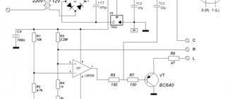
All sizes of current clamps operate using the Hall effect - the presence of transverse voltage that occurs when a conductor is placed in a magnetic field. Inside the housing there is a transformer that determines the intensity of magnetic oscillations, converting their value into an indication of alternating or direct current. Therefore, even if the resulting potential difference is small, the sensor will detect a magnetic field. This voltage, which is proportional to the current, is then amplified and measured (see Figure 1). Very powerful currents are measured in this way.
Figure 1. AC current measurement circuit
How to measure current using a transformer
When a conductor is passed through the terminals of the device, current passes through these terminals, acting as the iron core of a power transformer. Next, the current flows into the secondary winding, which is connected through the meter input shunt. Due to the ratio of the number of secondary windings to the number of primary windings wound around the core, the current entering the input is much less. Typically, the primary winding consists of one conductor, around which the jaws are clamped. If the secondary winding has, for example, 1000 turns, then the current in the secondary winding will be 1000 times less than that flowing through the primary winding. Thus, 1 ampere in the conductor being measured will produce only 1 milliampere at the instrument input. By increasing the number of turns in the secondary winding, powerful currents can be easily measured.
How to measure direct current, because it flows through conductors with a fixed polarity? Here the magnetic field around the conductor does not change, and it is impossible to record the corresponding readings in the usual way. Therefore, the clamps around such a conductor are closed with some gap (see Figure 2).
Design and main functions of current clamps
Current clamps carry out the necessary measurements without breaking or disconnecting the electrical circuit. Some models have additional functions that allow you to measure voltage, frequency and temperature.
The main advantage of this instrument is the ability to carry out measurements over a wide power range, with a maximum value of up to 1 thousand kilowatts. The standard circuit contains the magnetic clamps themselves, a range and function switch, a display, buttons that record measurement results and connectors. Basic functions include AC/DC current and voltage measurements, resistance measurements, diode testing, and fault testing. The tool is equipped with special protection that prevents overload.
There is such a thing as transformer signal amplification. This effect underlies the operating principle of transformer clamps. As a result, all measurements are carried out in a fairly simple way. The conductor being measured is inserted into the sliding magnetic circuit system. At this moment, it acts as the primary transformer winding for the magnetic circuit coil. The electric current flowing through the conductor will have different characteristics, which will be reflected in the measuring part.
Thus, taking into account the principle of operation, all current clamps are divided into devices for measuring direct or alternating current. Some types of models, made in a combined version, allow you to measure both quantities.
Current clamps are widely used in industry and at home. They are a multifunctional device that allows you to determine the actual load of the electrical network, the power of various devices and devices. Using current clamps, you can determine the amount of electricity consumed. any instruments and devices.
When working with this tool, you should take into account possible shortcomings in its operation. So, the location of the device completely affects the readings obtained. Among cheap devices there are often those whose measurement results are highly questionable. And finally, correct and accurate readings largely depend on the ability to use this device.
Technology of use
The instructions for current clamp meters are not very complicated. The main thing is to study the possible measurement modes and use the device in accordance with it. If it is necessary to make measurements on a single wire, then the appropriate mode is selected. To do this, the switch handle is moved to the desired position.
After fixing the measurement range, you should attach the pliers to the wire, grasping the conductor, and position the device perpendicular to the direction of the core. After this, you need to determine the results on the screen.
If the number “1” is recorded on the display, this indicates an overload, which means you need to move the switch to a higher range, having first disconnected the device from the wire.
Often it is not possible to isolate a single wire, for example, when measuring a cable coming from an outlet. When work is carried out, the indication “0” will appear. This indicates that the currents in phase and zero are equal in magnitude, although they will be different in the direction of the current.
When taking measurements on a power cable, several wires are inserted into the pliers. In this case, you need to select the appropriate mode.
If you want to learn how to properly use a clamp to measure voltage, you need to connect the red probe wire to the “VΩ” connector and the black wire to the “COM” connector. Using the switch, you will need to select the mode and set the measurement limit. After connecting the probes to the source, an indication of the polarity and voltage value will appear.
Similarly, resistance can be measured by connecting probes. But the switch should be moved to the “Ω” position. If the circuit has a resistance greater than 50 ohms, a warning signal will sound.
How to calculate current strength, calculate power, amperage - Construction
Probably, everyone who has done or is doing electrical repairs has encountered the problem of determining one or another electrical quantity.
For some, this becomes a real stumbling block, but for others, everything is extremely clear and there are no difficulties in determining this or that value.
This article is devoted specifically to the first category - that is, for those who are not very strong in the theory of electrical circuits and those indicators that are characteristic of them.
So, first, let's go back a little and try to remember the school physics course regarding electrical engineering. As we remember, the basic electrical quantities are determined on the basis of just one law - Ohm's law. It is this law that is the basis for absolutely any calculations and has the form:
Note that in this case we are talking about calculating the simplest electrical circuit, which looks like this:
We emphasize that absolutely any calculation is carried out using this formula. That is, by means of simple mathematical calculations, one can determine this or that value while knowing two other electrical parameters.
Be that as it may, our resource is designed to make life easier for those who do repairs, and therefore we will simplify the solution to the problem of determining electrical parameters by developing basic formulas and providing the opportunity to calculate electrical circuits online .
How to find out the current knowing the power and voltage?
In this case, the calculation formula is as follows:
Online current calculation:
(We enter non-integer numbers separated by a dot. For example: 0.5)
How to find out the voltage knowing the current strength?
In order to find out the voltage, while knowing the resistance of the current consumer, you can use the formula:
Online voltage calculation:
If the resistance is unknown, but the consumer power is known, then the voltage is calculated using the formula:
Online measurement:
How to calculate power knowing current and voltage?
Here it is necessary to know the magnitude of the effective voltage and effective current in the electrical circuit. According to the formula provided above, power is determined by multiplying the current by the effective voltage.
Online circuit calculation:
How to determine the power consumption of a circuit with a tester that measures resistance?
This question was asked in a comment on one of the materials on our site. Let us hasten to answer this question. So, first, we measure the resistance of the electrical appliance with a tester (to do this, just connect the tester probes to the power cord plug). Having found out the resistance, we can determine the power, for which we need to divide the voltage squared by the resistance.
Online calculation:
Formula for calculating wire cross-section and how the wire cross-section is determined
Quite a lot of questions are associated with determining the cross-section of the wire when constructing electrical wiring. If we delve deeper into electrical engineering theory, the formula for calculating the cross section looks like this:
Of course, in practice, this formula is used quite rarely, resorting to a simpler calculation scheme. This scheme is quite simple: the current strength that will act in the circuit is determined, after which the cross-section is determined according to a special table. You can read more about this in the material – “Wire cross-section for electrical wiring”
Let's give an example. I have a 2000 W boiler, what size wire should it be to connect it to household electrical wiring? First, let's determine the current strength that will act in the circuit:
I=P/U=2000/220V = 9A
As you can see, the current strength is quite decent. We round the value to 10 A and refer to the table:
Thus, our boiler will require a wire with a cross-section of 1.7 mm. For greater reliability, we use a wire with a cross-section of 2 or 2.5 mm.
- We recommend that you read:
- — POWER SUPPLY FOR LED STRIPS
- — PROTECTIVE NULLING
- — LED LIGHTS — YOU CAN’T IMAGINE BETTER!
- — DIAMOND CUTTING OF CONCRETE AND RC STRUCTURES
- Author - Anton Pisarev
ElektroMaster.org DIY repair and maintenance of household electrical appliancesTips, guides..
Yandex.Direct
Ammeter is a device for measuring current in amperes. The scale of ammeters is calibrated in microamperes, milliamperes, amperes or kiloamperes in accordance with the measurement limits of the device.
In an electrical circuit, the ammeter is connected in series with the section of the electrical circuit in which the current is measured; to increase the measurement limit - with a shunt or through a transformer.
(An example of an ammeter with a transformer is a "current clamp"
Ammeter
Current clamp - Ammeter for non-contact measurement of large currents, allows you to measure current strength in a non-contact way with high accuracy, without interrupting the power supply to consumers.
When measuring current, the clamp probes, in which ferrite cores are mounted, seem to wrap around the conductor, remaining completely isolated from open sections of the wires.
Important
Due to the formation of an oscillatory circuit by ferrites when current flows through the conductor, magnetic induction occurs, the value of which is directly proportional to the current flowing through the conductor.
This value is recorded by the current sensors of the current clamps and is converted into a current value, which is either displayed on the display of the current clamps (if it is designed) or outputs the value to an external multimeter through remote probes. Depending on the modification, current clamps can measure the strength of both direct current and alternating current.
Current clamps
general characteristics
The most common ammeters are those in which the moving part of the device with the pointer rotates through an angle proportional to the magnitude of the current being measured.
Ammeters are magnetoelectric, electromagnetic, electrodynamic, thermal, induction, detector, thermoelectric and photoelectric.
Magnetoelectric ammeters measure direct current; induction and detector - alternating current; ammeters of other systems measure the strength of any current. The most accurate and sensitive are magnetoelectric and electrodynamic ammeters. Operating principle
The principle of operation of a magnetoelectric device is based on the creation of torque due to the interaction between the field of a permanent magnet and the current that passes through the winding of the frame. An arrow is connected to the frame, which moves along the scale. The angle of rotation of the arrow is proportional to the current strength.
Electrodynamic ammeters consist of fixed and moving coils connected in parallel or in series. The interaction between the currents that pass through the coils causes deflections of the moving coil and the arrow connected to it. In an electrical circuit, the ammeter is connected in series with the load, and at high voltages or high currents - through a transformer.
The material partially uses information from wikipedia.org
Procedure for working with current clamps
Methods for measuring using current clamps are generally no different when using household multimeters (up to 1000 Volts) or professional (over 1000 Volts) devices.
A mite tester designed for home use will have many more functions, but a specialized device in a domestic setting will most often have nothing to measure.
Depending on the purpose of the measurements, the entire process using clamps combined with a multimeter will proceed as follows:
- Among the wires, the one from which readings need to be taken stands out. If you grab several conductors with pliers at once, the measurement result will be incorrect.
- The tester sets the required mode and range. If alternating current is measured, then it will be the letters AC, and when the device supports direct current measurement, then it will be DC. In this case, on the scale you need to select a value slightly larger than the one you plan to measure. If the estimated current strength is unknown, then measurements should be started from the largest scale.
- The pliers open and the required conductors are placed inside. For the most accurate measurement, it is advisable to place the wire in the center of the circuit, perpendicular to the body of the device.
- The measurement will take place automatically and the results will be shown on the display.
How to use current clamps »
The main task of electrical clamps is to measure current without breaking the conductor; modern devices have the functions of measuring voltage, capacitance, temperature, power, etc. The measuring principle is based on a current transformer or Hall effect.
Current clamps, operating on the principle of a current transformer, measure only alternating current, because The transformer does not pass direct current through itself. The primary winding is a wire wrapped around the current clamps, and the secondary winding is inside the current clamps with a current sensor.
If you wrap several turns of one conductor, the current on the secondary winding will increase by the same amount. This is convenient for measuring small alternating currents, in which case you need to divide the resulting current value by the number of turns.
Important
Externally, current clamps operating on a current transformer are distinguished by the absence of notches on the jaws and the absence of a direct current range.
Hall effect current clamps measure both direct and alternating current. The principle of operation of the Hall effect is based on measuring the voltage on the edges of a semiconductor wafer through which a direct current flows, placed in a magnetic field perpendicular to it. A magnetic field is formed around a conductor that is clasped by a current clamp.
A change in current in a conductor causes a change in the magnetic field around the conductor, which causes a change in voltage across the Hall sensor element. The voltage at the sensing element is converted and displayed as a current value
For hall effect current clamps, it is important to place the conductor perpendicular to the current clamp jaws
Current measurement
To work on our APPA 133 device, we will select the alternating current mode A~ and wrap around one wire. The selection of the measuring range in APPA 133 is automatic; in other devices it may be necessary to select a range. If the conductor is not placed perpendicularly or along the marks, then the reading error increases to 3%.
To measure inrush AC current, you must select the “inrush current” mode, for example, in the case of measuring the inrush current of an electric motor. To measure the max min current, select the appropriate mode. When the stove is on, the maximum current is 8.47 A.
If you grasp two wires at once, the current clamp will show zero, because the sum of the currents of two conductors with different polarities is zero.
If the instrument reading is not zero, then there is a leakage current or the value is within the instrument error. When measuring several wires at the same time, the current value will be the sum of the currents of all wires.
A current leak may appear, for example, if the water from the tap is electrifying, you need to check the leakage current of the electric boiler.
Voltage measurement
To measure direct and alternating voltage, set the switch to V. Our device has automatic range selection and also allows you to measure frequency. It is necessary to switch between modes with the wires disconnected. APPA 133 has high voltage protection over 1000 V.
We see a voltage of 221.1 V, a frequency of 49.97 Hz.
When the stove is turned on, we see that the voltage has dropped to 211.1 V, the frequency has not changed. This happened due to the fact that the cross-section of the wires is not enough for the power of the stove, which causes overload and heating of the wires. It is necessary to change the wires to a thicker section.
Power consumption measurement
Apparent power (V*A) is equal to the square root of the sum of the squares of active and reactive power. Reactive power (Var) is equal to the product of voltage and current multiplied by the sine of the phase angle between them. If there are no consumers with reactive power (motors, transformers), then the total load power will be equal to the active one.
Active power is calculated in the device using the formula voltage times current. If the device does not allow you to measure power, then multiply the resulting current by 220 V and get the load power. To measure active power using APPA 133, move the W~ switch. It is necessary to switch between modes with the wires disconnected.
We insert the probes into the socket and wrap around the conductor.
The active power consumption of the computer is 28 W, and with the stove on, the power consumption increased to 1728 W (~=211.1 V * 8.47 A). In APPA 133 you can also measure the power factor, a negative value indicates the capacitive nature of the load (current leads the voltage), a positive value indicates the inductive nature of the load (current lags behind the voltage).
You can select current clamps in the catalog.
Clamp meter
Hello, dear readers and guests of the Electrician's Notes website.
In previous articles, we got acquainted with insulating mites. Today I will tell you in detail about electrical clamps.
Please do not confuse these two phrases, because they are not the same thing. However, you will see this for yourself now.
Electrical clamps are used to measure current in electrical installations with voltages up to 10 (kV), as well as to measure voltage in electrical installations up to 1000 (V) without breaking the controlled circuit.
Electrical clamps apply ONLY to the main means of protection in electrical installations up to and above 1000 (V).
Design of electrical clamps
Almost every electrician probably knows what an electrical clamp looks like.
Electrical clamp meters have a built-in current transformer. The current transformer has a detachable magnetic circuit.
The primary winding is a conductor carrying the measured current. An electrical measuring device is used as the secondary winding.
Currently, there are a large number of electrical clamps of various types and models. Depending on the type and model of the clamp, the electrical measuring device can be either analog (pointer) or digital.
In this article, as an example, I use the M266 electrical clamp from my list of tools. I like them for their simplicity and reliability.
Electrical clamps up to 1000 (V) consist of a working part and a housing. The working part is used:
The body itself with a stop and a handle is used as the insulating part of the pliers.
Clamp meters above 1000 (V) consist of:
- working part
- insulating part
- handles
The working part of the pliers is a magnetic circuit, a winding and an electrical measuring device, which can be either removable or built-in in an electrically insulating housing.
The insulating part of electrical clamps above 1000 (V) must have a length of at least 38 (cm), and the handle must be at least 13 (cm).
To be honest, I have never had to use electrical clamps above 1000 (V) live.
Clamp meter testing
During operation of electrical clamps, it is necessary to carry out electrical tests on them. According to the Instructions for the Use and Testing of Protective Equipment Used in Electrical Installations (IPISZ), Appendix 8, the frequency of testing electrical clamps is once every 2 years (24 months), and the test duration is 5 minutes.
A test voltage of 40 (kV) is supplied between the magnetic core and a temporary electrode, which is installed near the limiting stop on the side of the insulating part. This applies to clamp meters up to 10 (kV).
For clamps up to 1000 (V), a test voltage of 2 (kV) is applied between the magnetic core and the base of the handle.
How to use?
Basic rule. It is allowed to use electrical clamps up to 10 (kV) ONLY while wearing dielectric gloves.
When measuring circuit parameters, the electrical clamps must be kept suspended. It is forbidden to lean towards the electrical clamp meter to take readings.
In an electrical installation up to 10 (kV), it is prohibited to use remote devices, as well as switch measurement limits. To switch the limit, you need to remove the clamps from the live part.
It is prohibited to use electrical clamps on overhead line supports up to 1000 (V), unless the clamps are specifically designed for this.
Below I will show you how to use a clamp meter.
Let me give you a clear example. Let's say that we need to measure the magnitude of alternating current. To do this, you need to switch the clamp limit to “ASA”, separate the magnetic circuit and wrap around the conductor (wire) going to the load of interest to us. A clamp meter will show us the amount of current in this conductor.
In my example, I did it a little differently. On a test bench to test relay protection, using a current source, I induced about 5 (A) in the conductor. This can be seen on the ammeter.
Now let’s check the current in this conductor using an electrical clamp.
The measured current using an electrical clamp was 5 (A), which corresponds to the value of the previously induced current.
Instead of electrical clamps, you can use a multimeter, or “tester”, as many call it. To do this, I have prepared a whole course for you, consisting of 3 parts:
Popular models
The difference in price may be due to both the use of a well-known brand and the materials used to manufacture the device. Let's look at the most popular current clamps on the Russian market.
Mastech 266
Mastech model M266
There are three modifications of these current clamps: M266, M266C and M266F. The additional letters C and F in the model names indicate the ability to measure temperature and frequency. The models do not differ in shape, color and other parameters.
Country of origin: Hong Kong. All current clamps of the M266 series measure:
- Alternating current – up to 1000 Amperes;
- AC and DC voltage – up to 1000 Volts;
- Resistance – up to 2 Mohm;
- Diode check
All models are supplied with high-quality electrical probes with good contact in the device. Convenient “Hold” button for recording readings on the screen under your thumb. Model cost:
M266 – $30;
M266C (with thermometer) – $31.50;
M266F (with frequency measurement) – $31.50.
Resanta DT 266
Resanta pliers DT 266
Chinese current clamps are of low quality and have a number of functional disadvantages:
- The probes quickly break at the junction of the cable and the plug.
- Poor dust protection of the device leads to contamination from inside the screen. If the device is used in dusty conditions, the screen becomes unreadable over time.
- Over time, play when opening the pliers leads to inaccurate connection of the jaws, and this leads to inaccuracies in measurements.
- There is no screen backlight. It is impossible to work in a room with poor lighting.
- The error of the device does not correspond to the declared one and is about 5%, which is unacceptable for such a multimeter.
- The response speed is very low compared to analogues. Voltage measurement lasts 2-5 seconds, current measurement lasts 6-8 seconds.
- Small symbols on the front panel of the device. It's difficult to make out what exactly is written. The paint with which the markings are applied is easily erased and after six months of work you can only switch from memory or by looking at the instructions
In general, the device is intended for use only in high voltage environments where high measurement accuracy is not necessary:
- Voltage DC/AC – 1000/750 volts;
- Connection testing;
- Resistance – up to 2Mohm
The undeniable advantage of this model is the price of $10.50, but considering that the service life of such a device will not exceed one year of active use, and during this time you will have to buy additional probes for it a couple of times, you will not get pleasure from using it.
Fluke 376
Fluke 376 Clamp Clamp with iFlex Sensor
One of the best devices in this segment. American quality is strikingly different from everything else on the market. High measurement accuracy (from 0.1%), protection from dust and adaptability to work in extreme conditions make these pliers the most popular among professional electricians.
A special feature of the device is a special iFlex sensor - which comes as standard. With its help, you can check the current in those cables, due to their cross-section or location, they cannot be grabbed with pliers. The sensor is connected to the connector from below.
Using iFlex for Measurements
The device is equipped with high-quality electrical probes that connect to the same connector. The display is white, the readings are easy to read, there is a backlight and a Hold button that “freezes” the readings at the right moment. Measurements:
- AC/DC – 1000 amps;
- Current using iFlex sensor - 2500 amperes;
- Voltage (AC/DC) – 1000 volts;
- Frequency 5 – 500 hertz;
The pliers operate on two AA batteries. Their only drawback is the high cost of $244.30, which, of course, is incomparable with Chinese crafts, but the professional quality of the device is worth the money.
Design
Modern current clamp meters, regardless of manufacturer and modification, contain the following elements: magnetic circuits with a movable bracket-lever, a switch for measurement ranges, a screen, output connectors for probes (in this case, the clamps can be used as a regular multimeter) and a button for fixing current measurements (photo below ).
Figure 1 – TK S-line DT 266 FT
Most modern current meters also include an internal diode bridge transformer. In this case, the terminals of the secondary winding are connected via a shunt. Depending on the range of measured currents, current clamps can be one-handed (for voltages up to 1000 V) or two-handed with additional insulated handles (for voltages from 2 to 10 kV inclusive). Current measuring devices intended for measurements of more than 1 kV have an insulator length of less than 38 cm, and handles of at least 13 cm.
As a rule, the safety category and the maximum measured current are indicated on the device body. For example:
- CAT III 600 V - this means that the device is protected from short-term voltage surges inside the equipment when operating in fixed networks with voltages up to 600 V.
- CATIV 300 V - this means that the device is protected from voltage surges inside primary power supply equipment with voltages up to 300 V. An example of such equipment is a conventional electric meter.
Device and principle of operation
Current clamps include several components.
- A magnetic circuit that is opened and retracted using a spring mechanism with levers (this mechanism resembles tongs).
- The housing contains a measuring device, which includes a display (or a pointer electrical measuring head), a measurement range switching board with a multi-position switch. Digital devices can have either an electronic board with the functionality of a full-fledged multimeter or an ammeter. In more “advanced” devices, instead of a switching unit, there is a digital selector that automatically selects the desired measurement limit. The universal device with current clamps has separate connectors for selecting voltmeter or ohmmeter mode. The latter mode is used for measurements on disconnected electrical installations and circuits.
- The analog device is also equipped with additional calibration variable resistors - they help to more accurately establish the measurement zero if it is lost. This is necessary for extremely accurate measurements.
- If the current is measured in protected and difficult-to-access circuit points, the current clamp device includes a meter with a highly sensitive and flexible probe.
The operating principle of current clamps is as follows. It is based on the effect of electromagnetic induction. The wire on which the operating (load) current is measured is inserted into the gap of the magnetic circuit. There is a secondary winding on that one. The primary current on the wire being measured creates an alternating magnetic field around itself, which is captured by the magnetic circuit. It, in the form of a magnetic flux, reaches the secondary winding and induces an induced emf in it. The magnitude of the current in the wire and the secondary current generated in the coil are strictly correlated, and the primary current is easy to estimate.
Since an unbroken ring of the magnetic circuit would require the insertion of a section of wire folded in half, on which the current is measured, and the measurements would be very inaccurate, the magnetic circuit is made in the form of round pliers - a break is formed in it when the handles are pressed, and only when this wire needs to be put on tool.
For example, transformer steel can be used as a magnetic core - if we are talking about an industrial frequency of 50-60 hertz. The difference between clamps and a current transformer is that the latter has an unbroken ring or a rectangular contour.
But a special breakthrough in this area was achieved thanks to the discovery and introduction into use of electricians and power engineers of the Hall sensor. It allows you to measure not only alternating current, but also direct current - using the same current clamp method.
Measuring current in electrical networks
Current strength is measured in amperes and characterizes the load on electrical networks. The need to measure current arises to check whether the load on the cable is acceptable. Cables of various sections are used for installation of electrical wiring. Permissible currents for cables with polyvinyl chloride insulation laid over the air are:
| Core cross-section, mm2 | Aluminum conductors in quantity | Copper conductors in quantity | ||||||
| 2 | 3 | 4 | 5 | 2 | 3 | 4 | 5 | |
| 1,5 | 24 | 21 | 20 | 20 | ||||
| 2,5 | 25 | 21 | 20 | 20 | 33 | 28 | 26 | 26 |
| 4,0 | 34 | 29 | 27 | 27 | 44 | 37 | 34 | 34 |
| 6,0 | 43 | 37 | 34 | 34 | 56 | 49 | 46 | 46 |
If the cable line load exceeds the permissible limit, the cable will heat up and its insulation will be destroyed. As a result, this will lead to a short circuit, and the cable will have to be replaced with a new one.
Therefore, after replacing the cables, measure the current flowing through it when connecting all electrical appliances. If the electrical wiring is old, then when connecting an additional load to it, you also need to check whether the currents in it correspond to the permissible values.
When the electrical wiring is under maximum load, you can check whether the current through the circuit breakers corresponds to their rated data. If the rated current of the machine is exceeded, its operation due to overload is inevitable.
Measuring current is required to determine the operating modes of electrical appliances. Measurement of load currents of electric motors is carried out not only to monitor their serviceability (currents in all phases must be the same), but also to determine the presence of overload due to increased torque on the shaft. For a heater, measuring the current will show whether all its heating elements are working properly. Only by measuring the load current can you find out whether the heated floor is working.
Electric current power
Power is the work done by electric current per unit time. It is measured in Watts (W, W). It is theoretically possible to measure power directly, but for this purpose special devices are used - wattmeters, which measure the current through the load and the voltage across it. They give readings in Watts, but connecting them is too difficult. Therefore, they are used for measurements at predetermined nodes of the electrical network, connecting to them once and for all.
Panel wattmeter for measuring current
For domestic use, the power is calculated after measuring the current consumed by the load and the voltage across it, which for simplicity can be taken equal to 220 V.
This method does not always give accurate results. When there is inductive reactance in the load, the active power is affected by the power factor. Some electrical appliances consume non-sinusoidal current (LED and energy-saving lamps, computer and television equipment), which not all measuring instruments designed to measure alternating voltage measure correctly.
Instruments for measuring current strength
You can measure current using the following instruments:
- ammeters . Like wattmeters, they are used for stationary measurements.
Current measurement: panel ammeters
— multimeter – a multifunctional device with a digital liquid crystal display (how to use a multimeter?);
Current measurement: multimeter with clamp meter
- tester - a device that measures several quantities, but, unlike a multimeter, has a dial indicator;
Current measurement: tester
— current clamp - a device that allows you to measure current without breaking the electrical circuit.
Current measurement: clamp meter
Current measurement methods
Unlike measuring voltage, current is measured not when the device is connected in parallel to the load, but when connected in series. This means that the measuring device must be connected to the break of any of the power wires of a single-phase consumer. With three-phase power, the same must be done for each phase. In this case, the current in the neutral wire is not measured, since with a symmetrical load it is zero. Sometimes it is necessary to measure the current in the neutral conductor, but for a group of consumers, disconnecting the neutral to make measurements is impossible.
Connecting an ammeter when measuring current
All these reasons lead to the fact that testers and conventional multimeters are rarely used to measure current. They can only be used for a single consumer or for DC measurements.
In all other cases, current clamps or multimeters containing them are used. To take measurements, simply press the key to release the clamps, place the conductor with the current being measured inside the measuring circuit, and release the key. The magnetic circuit of the clamps will close and the display (there are clamps with a scale and arrow) will show the measured value.
How to use a clamp meter
The value of the basic electrical parameters can be obtained using certain instruments. One of these devices is special pliers that allow you to take readings without breaking the chain.
These “smart” devices are very often used, as they allow you to obtain several types of parameters. You can purchase measuring clamps in almost any specialized store, where you can also immediately get advice on their use.
Main characteristics
Clamp meters are a special mechanism that allows you to determine the strength of alternating current without breaking the main circuit.
This product consists of several main components:
- magnetic circuits that can open and close in a certain way;
- range switch;
- display;
- output connectors for probes;
- buttons for fixing current measurements.
The clamp meter can also be used as a regular multimeter, making its design versatile. Each type of device must indicate the safety category and the maximum measured current.
There are several types of ticks, which allows them to be used in certain networks.
What do clamp meters measure?
First of all, what clamp meters are designed for is, of course, to measure current. Moreover, the measured value is much higher than the value measured by a multimeter.
Depending on the design, only AC current or any current form can be measured. For home use, clamps are produced with operating voltages up to 1,000 V; for electrical personnel, devices capable of operating at voltages up to 10,000 V are used.
Modern devices, in addition, can measure voltage, frequency, power. More universal devices are equipped with a multimeter with all its functions. One such device can replace several simple devices. Let's look at how to use current clamps; to do this, let's look at how they work.
Current clamps - what are electric clamps used for?
A current clamp is a device whose main function is to measure electric current without a break in the measured circuit. According to the voltage of the circuits in which measurements are made, current clamps are divided into devices up to 1000V and above 1000V.
Current clamps can be one-handed (the usual type for measurements in networks up to 1000V) and two-handed (high-voltage, for networks with voltages up to 10 kV). High voltage clamps must undergo high voltage tests periodically.
In practice, current clamps are most often used for measuring alternating current in 220V/380V networks, but recently clamps have also been used for measuring direct current, as well as combined clamps.
Current clamps are available in analog (arrow) and digital (with liquid crystal display).