Voltage and multimeter
Let's see how to measure voltage with a multimeter. First of all, you need to check the location of the device toggle switch. To prepare the device for measuring voltage, you need to turn it from the off position (indicated as “OFF”) to the V~ mark (the English letter “V” and a wavy line indicating alternating voltage). On some multimeters this mode is abbreviated “ACV”. AC Voltage Test Steps:
- Install the red probe into the socket marked “V/Ω” or “VΩmA” (this is the positive potential), the black one into the “COM” socket.
On a note ! Since alternating voltage has no polarity, installing the probes into the precisely indicated connectors does not play any role. But if the black probe hits a phase, then the number on the screen may be negative.
- Check the switch (it should be at the V~ mark).
- Setting the test level (if you plan to measure alternating voltage in an electrical network with a nominal value of 220 Volts, you should set the test level to a slightly higher value, for example, 236 V, or perhaps to the maximum).
- Inserting the probes into the socket, for the voltage in which it is necessary to check.
Numbers indicating the desired alternating voltage will appear on the screen of the electronic multimeter.
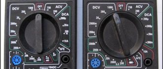
Dial multimeter in the off state Source img1.bgxcdn.com
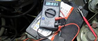
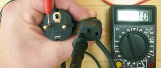
Next, we'll look at how to use a voltage tester to check battery voltage. To measure DC voltage with a dial or electronic multimeter, insert a red and dark probe into the “V Ω mA” and “COM” sockets, respectively, then turn the switch to “V-”.
After setting the verification level (you will need to set it, as in the previous example, to a slightly larger digital value than the intended measurement object has). The two free ends of the probes must be connected to the object being tested (for example, to the two ends of a battery), observing the polarity (“+” and “-”).
On a note ! If you make the wrong polarity, the multimeter will show a negative value, but the value itself will be the correct number; you need to swap the probes on the battery so that the polarity is correct.
If a value with one or two zeros in front, but without a comma, appears on the device screen, it means that the test level was set too high. It is necessary to achieve a normal number by gradually reducing it and taking measurements. For example, for a battery the value “008” may first appear, and after the indicated manipulations - “8.9”. This means that the battery voltage is approximately 9 Volts.
The multimeter shows the battery voltage Source masteram.com.ua
When “1” appears on the screen, the pre-selected measurement threshold may be too high, then it needs to be brought to a suitable value by gradually decreasing it.
How to measure DC voltage with a multimeter
Make sure the probes are connected correctly.
YouTube channel electronoff
Switch to constant voltage mode. It is usually denoted by the symbols V with a straight line and a dotted line, or DCV.
In multimeters with manual range selection, additionally set the approximate measurement value, or preferably one step higher. If you are not sure, start with the maximum and gradually lower.
YouTube channel electronoff
Touch the probes to the contacts and look at the screen. If a minus sign is displayed along with the number, it means that the polarity is reversed: the red probe touches the minus, and the black probe touches the plus.
YouTube channel electronoff
In a hand-held multimeter, you may have to adjust the measuring range.
YouTube channel electronoff
If the display shows a unit, you need to increase the measurement limit; if it is zero, the OL or OVER symbols need to be lowered.
Checking the current strength
Let's see how to use the tester to find out the current strength:
- Insert the red connector into the socket marked “mA” (“VΩmA”), the black one into “COM” (to check the current strength, the value of which does not exceed 10 Amps). To check the current, which ranges from 200 milliamps to 10 amperes, you should put a red electrical probe into the “10A” connector.
Different positions of drills to determine small and large currents Source www.sciencebuddies.org
- Place the switch on the “A~” mark to check the alternating current value or on the “A-” mark to check the direct current strength.
- Set the measurement range so that it is greater than the expected current strength, but not by much.
- Connect the load (for example, an incandescent light bulb with a socket) into the assembled electrical circuit from the outlet to the multimeter.
Important ! You cannot touch the circuit elements that are not insulated with your hands and the ends of the probe.
- Attach a piece of wire to the lamp base, and the other end to the probe.
- Take another wire and attach it according to the “lamp base - electrical outlet” diagram.
- The red probe (its free end) must be set to the “+” of the object being measured, and the black probe must touch the next element of the circuit (the wire coming from the “load”, that is, from the light bulb).
Remember ! For correct, and most importantly, safe measurement of current, it is necessary to connect the multimeter to the electrical circuit in series, since in ammeter mode the resistance of the multimeter circuit is minimal and if connected in parallel there will be a short circuit.
Connection diagram for a multimeter with a “load” Source electrikmaster.ru
See also: Catalog of companies that specialize in electrical and heating systems
A multimeter can also be used to determine the amount of AC current consumed (for example, for a household appliance). After installing the switch on the direct current symbol (“A-”), you should arrange the probes as follows: for high current - the extreme left position (o), for low current - the middle position (o).
Having set the measurement range approximately corresponding to the current, but slightly larger, you can proceed to the next stage, not forgetting that the device can only be turned on in an open circuit (as in the previous example).
Appearance of the multimeter
A multimeter is a universal device for measuring electrical characteristics that combines many functions (depending on the model). In the minimum configuration, such a device consists of an ammeter, voltmeter and ohmmeter. In the most common version, it is performed digitally and portable. Externally it has a rectangular shape with a display and a rotary or push-button function switch. To perform measurements, two probes (red and black) are connected to the multimeter in strict accordance with the markings on the device.
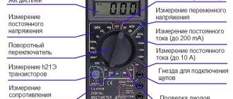
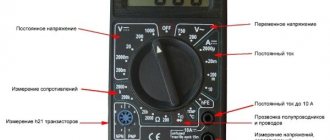
Brief description of the measured parameters and their designation
Manufacturers use standard markings in English or special symbols to indicate parameters on multimeters. To operate the device, it is important to know the basics of electrical engineering in order to correctly and safely carry out the necessary measurements.
Each device is divided into zones with settings for working with a certain type of electrical network voltage:
- ACV or V~ – alternating current voltage;
- DCV or V- – DC voltage;
- DCA or A- – direct current strength;
- Ω is the resistance in a section of a circuit or in an electrical device.
Purpose of connectors for connecting probes
Depending on the multimeter model, the number of sockets for connecting probes may vary. It is necessary to connect the probes for measuring the electrical parameters of the network into the correct sockets of the device. For most measuring instruments, the sockets are marked as follows:
- 10A- – for measuring direct current not exceeding 10 A (a red positive probe is connected to this socket);
- VΩmA or VΩ, V/Ω - a red (positive) probe is connected to this socket when determining voltage, direct current up to 200 mA, for continuity testing of diodes and circuits;
- COMMOM (COM) – common socket for the black (negative) probe on all types of multimeters;
- 20A - such a socket does not exist on all models (most often it can be found on expensive professional devices), the task of this socket is similar to 10A-, but with a limit of up to 20 A.
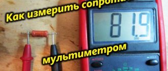
Multimeter and resistance
To find out the resistance of any radio component, use a conventional multimeter. Measurement algorithm:
- Insert the probes (black – into the “COM” socket, red – into the socket marked “V/Ω” or “VΩmA”).
- The switch will need to be moved to the “Ω” position.
- At the third stage, it is advisable to check the serviceability of the device by connecting the two remaining free ends of the probes. The multimeter is working if it shows a zero value.
- Set the measurement limit to the expected approximate average value (for example, 2 M).
- Connect electrical probes to the coil (to the measurement object).
What will be the coil resistance? Source cdn.sparkfun.com
- Look at the display (screen) of the device.
If several zeros appear, the coil has resistance, but the measurement limit will need to be lowered slightly to see the actual digital resistance value. The same must be done when a number appears in front of the numerical value on the electronic multimeter, but with a zero (zeros) at the beginning. If a unit occurs, it is worthwhile, on the contrary, to reduce the set denomination.
Types and designs of modern multimeters
Today I produce two types of testers for everyday use:
- analogue, in which the level of measured parameters is read on a scale with an arrow;
- digital, the liquid crystal or LED indicator (display) of which displays the digital value of the measured parameter.
To connect to the measurement object, the multimeter is equipped with probes, the pointed ends of which are connected to the points for measuring voltage, capacitance, current and other parameters. To connect to the device, the probes are equipped with flexible multi-colored wires with plugs. In this case, the black wire usually corresponds to the negative conductor, and the red wire to the positive one. The corresponding sockets on the front panel are also marked with the same color.
However, multi-colored painting does not carry any functional load, but is performed only for the convenience of the user. The latter are connected to the device sockets. For ease of use, crocodile clips can be attached to the tips of the probes.
Today, digital instruments are becoming increasingly popular, while analog (pointer) instruments are gradually fading away. An undoubted advantage of digital models is that most of them do not require polarity when connecting probes.
If you measure the battery voltage with a digital device and confuse “plus” with “minus,” you can bend the indicator needle. A digital tester will display the current voltage value on the indicator, only with a minus sign.
A simple, household Chinese tester that allows you to measure:
- alternating and direct voltage in the range 0...1000.0 volts;
- current in AC and DC circuits;
- active resistance.
can be purchased for 200.0...250.0 rubles.
A tester that additionally allows you to measure the basic parameters of transistors and diodes, as well as determine the temperature using a thermocouple or thermistor, will cost no more than 500.0 rubles.
If earlier the selection of the measurement range (limit) was carried out by “sticking” the plug into various sockets on the front panel of the device, today the vast majority of devices have a batch switch, by rotating the handle of which the desired limit is set.
Before using a multimeter tester, you need to study the designation of the sockets located on the front panel of the device, to which plugs are connected for measuring various types of electrical parameters.
On simple devices designed to measure voltage, current and resistance, there are several sockets designated by the abbreviation “ACV”, “DCA” and some other letters (depending on the model and functionality of the device). In these notations the letters mean:
- “DC” – socket for measuring direct current parameters;
- “AC” – socket for alternating current;
- “V” – voltage (“V” – “V” – volts);
- “A” – current (“A”) – amperes).
In some models, the three-digit designation may be absent and the sockets are designated more clearly: “V~”, “V±”, “A” and some others.
Testing with a multimeter
The multimeter has several more functions, one of which is the so-called continuity test. It is used to search for a break in the neutral wire in an electrical circuit.
Algori:
- connect the red probe to “V/Ω”, the black one to “COM”;
Testing wires with a multimeter to check their integrity Source avatars.mds.yandex.net
Checking radio components
If a radio amateur has a digital multimeter, he must know how to use this device to test the functionality and measure the characteristics of transistors, diodes and capacitors. Everything is very simple here:
A black probe should be installed in the COM socket, and a red one in the VΩmA socket.
The black probe (its second end) must be connected to the cathode of the diode (to the “minus”) of the part being tested, and the red one, respectively, to the cathode of the anode (to the “plus”).
The resistance of the part will be displayed on the screen.
If in any position (as in the described algorithm or with the reverse arrangement of the probes connected to the anode and diode) one is displayed, this means that the part has burned out. If the reading is less than one, the diode is broken.
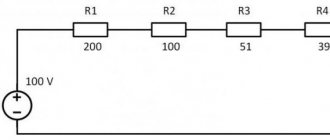
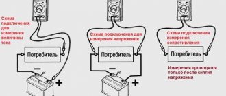
Electrical measurements
When measuring the values of the parameters of interest, you need to know:
- voltage is measured by connecting the tester probes in parallel to a source (electrical outlet, battery terminals);
- current is measured in an open circuit;
- resistance, capacitance, inductance - when connecting probes to the terminals of an object whose parameters need to be measured.
At the same time, the accuracy of measurements for household testers is usually 1.0%...3.0%, which is caused by circuit design solutions and the electronic parts used. Let's consider the procedure for various measurements.
DC and AC voltage
Direct and alternating voltage are measured as follows.
We connect the plugs to the sockets on the front panel:
- black wire to the negative (mass) jack marked with , “COM” or “┴»;
- red to the “DCV” socket when measuring direct voltage or to “ACV” - for alternating voltage;
- by rotating the switch handle, select the desired range;
- connect the probes to the contacts (terminals, sockets) of the measured source;
- We read the voltage value from the display.
The accuracy of AC voltage measurement is affected by the resistance of the diodes, which convert it to DC. However, usually the measurement accuracy is quite sufficient for domestic needs.
Types of test screwdrivers
When determining the current value
When determining the current value, the plug is connected to the device in the same way, and the probes are connected to an open circuit, for example, between a light bulb and a battery, or an electric stove and a power outlet. In this case, it is quite important to determine the measurement range, because an increased level of current flowing through the device can lead to its breakdown.
Therefore, in some models for measuring large values of alternating and direct current there are separate sockets or values on the switch scale, designated as “DC10A” or “AC20A”.
Resistance measurement
Measurement of the resistance of a resistor, filament of a lamp or electric stove must be carried out on a de-energized object. To measure the value, perform the following steps:
- We move the device switch to the range designated “Ω”;
- we connect the probes to the ends of the resistor or the contacts of the light bulb;
- We read the measurement value from the display.
To increase the reliability of the result, the measurement of a specific sample should be carried out at different positions of the range switch. Similarly, you can determine whether a wire is broken. If the device shows a zero value, then the wire is working. If the readings fluctuate or are not determined, the wire may break.
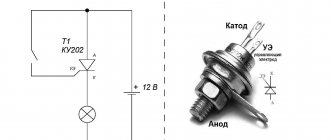
Diode continuity test
Diode continuity testing is also carried out in resistance measurement mode. The red and black probes are alternately connected to the diode terminals. In one case, the resistance will be quite large, in the second it will be at the level of hundreds of ohms - several kilo-ohms.
This procedure alone makes it possible to determine the absence or presence of a breakdown of the “p-n” junction. If the tester, when connected to a diode, shows a value in ohms - kiloohms, then the red probe is connected to the anode of the electronic device.
Video description
You can see more details about how this test is carried out in the video:
To check the transistor, you need to switch the multimeter to the “hfe” mode and combine the three outputs of the part with the connectors on the device. They are called "B", "E" and "C" and correspond to the "base", "emitter" and "collector" on the transistor. If the connection is correct, the gain value of the radio component being tested will appear on the multimeter screen.
So, how to use a multimeter tester to check the capacitor for its capacity: this part must be inserted into the corresponding connectors on the device (the “CX” sector). By twisting the toggle switch, you can adjust the measuring limits to the required numerical value.
Notations and modes
Let's look at the main controls of the device. Multitesters, how to use - there is a multi-position switch on the front panel. Using the switch, you can select the following operating modes of the multimeter:
- OFF — mode to turn on/off the device;
- V~ - mode of measuring alternating voltage values;
- V= – mode of measuring DC voltage values;
- A~ - alternating current measurement mode;
- A= – DC current measurement mode;
- Ω — circuit resistance measurement mode;
- hFE - mode for measuring transistor parameters;
- ->|- — diode polarity detection mode.
Also on the front panel there are sockets for connecting probes. Probes are necessary for taking measurements, as they connect the device itself to the measuring point. As a rule, probes are included with the multimeter. In inexpensive Chinese devices, the quality of the probes leaves much to be desired, and the probes of such devices fail very quickly.
In this case, it is recommended to buy separately higher-quality probes at a radio store or make them yourself. For example, you can reinforce the junction of the wire with the probe with electrical tape so that the wire does not break. You can also make your own additional probes, terminated with alligator clips, with an extended wire. This will significantly expand the functionality of the device.
Video description
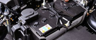
Learn how to quickly check a car battery with a multimeter in this video:
Checking a car battery using a multimeter Source mobilehomepartsstore.com
Further measurements will be made in the same way. To measure the current strength in the wiring of your car or for a separate electrical appliance, you should first find out what kind of current you need to check (for example, the “DCA” marking indicates constant). To measure resistance, set the toggle switch to any position, and do not forget to turn off the power to the network.
Additional functions
Modern models of household multimeters often allow you to check the parameters of bipolar transistors, as well as determine the inductance of coils and the capacitance of capacitors. For this purpose, there is a special range on the switch scale.
Checking transistors
Checking transistors is a rather specific procedure and is required only by persons involved in the repair of electronic equipment. To determine the performance of a bipolar triode, a procedure similar to diode testing is used. The probes are alternately connected to the “base-emitter” and “base-collector” terminals.
If the instrument readings correspond to the readings as when checking the “p-n” junction of the diode, the transistor can be considered serviceable. However, it will not be possible to determine the gain in this way.
Determination of capacitance and inductance
Capacitance and inductance are determined by switching the multimeter to the range “L” (inductance) and kb “C” (capacitance). The plugs of the device are connected in the same way as for measuring resistance. When determining the capacitance of electrolytic capacitors, the polarity of the connection must be observed.
When measuring resistance, capacitance and inductance, as well as when working with diodes and transistors, you should use alligator clips. If the probes are pressed to the terminals with your fingers, then the resistance of the human body can introduce a fairly large error in the measurement result.
Briefly about the main thing
Any car enthusiast, radio enthusiast, or anyone who encounters electric current or the operation of household appliances should know how to use a multimeter correctly.
By following a few simple steps, you can find out the voltage, current, and resistance of an electrical circuit using any type of multimeter.
Car batteries, radio components and electrical devices can also be examined using a multimeter tester.
Ratings 0
Popular multimeter models
Conventionally, all manufactured devices of this type can be divided into groups according to:
- application - home “what if you need it”, relatively permanent for repairing and testing electrical appliances and networks, professional;
- type – portable and stationary. The latter usually refer to professional or semi-professional;
- the range of tasks to be solved - only the simplest measurements, advanced functionality without special settings, advanced functions with the possibility of precise settings;
- measurement accuracy – sufficient for everyday tasks or professional use;
- price. The cost of devices ranges from hundreds of rubles to thousands, depending on the capabilities, quality and popularity of the manufacturer.
Important: the device models listed below are not trade names and are in no way associated with the manufacturers. These are just certain modifications of devices with different functionality.
Multimeter dt 830b: instructions for use
This relatively simple device has all the basic functions.
There are only three connectors for the probe, so you won’t be able to use the device to measure currents above 10A. But it is possible to check transistors and diodes.
When figuring out how to use the dt 830b (dt 830v) multimeter, it is worth considering: on its display, when setting the maximum measurement range in the current measurement mode (500 V), a warning appears that this is the highest value - HV (high voltage) - and working with the device requires caution.
Good to know: in this model, the polarity of connecting the probes is not important. If a plus is confused with a minus, a “-” sign will appear on the display, but the value will remain correct.
When measuring resistance (at small values), do not neglect the resistance of the probes themselves. You can determine its value by connecting the probes to each other. Subsequently, this value is subtracted from the measured resistance value of the device or section of the electrical circuit.
It is worth noting the features of this cheap model:
- relative fragility of plastic (should not be dropped);
- average quality of probes;
- measurement error is about 1%;
- changing the measurement mode manually (by turning the knob);
- display without backlight.
Supplied complete with: multimeter DT 830v, instructions for use (paper, not always of normal quality, especially when buying a Chinese device), probes.
If you need to more accurately understand how the dt 830b multimeter works, instructions with a detailed description can be downloaded here: dt 830b multimeter: instructions.
A more convenient option “for dummies” is an overview of the operating modes in the video, the nuances of working in different measurement modes.
Multimeter dt 832: instructions for use
In terms of characteristics and functionality, this device differs little from the previous model.
The main difference is the ability to measure temperature using a thermocouple (not available from all manufacturers; availability should be checked before purchasing. A thermocouple can be connected additionally) and overload protection in all measurement modes. There is also a low battery indicator, but users note the inconvenience of replacing it - the back cover, under which the battery is hidden, is secured with small screws, not hooks.
In addition to this inconvenience, the disadvantage of the model is also considered to be the fragile body and the measurement error within 1% according to the documentation, which in reality reaches 2...3% depending on the build quality.
Instructions on how to use the dt 832 multimeter can be found in an easy-to-print PDF format: dt 832 multimeter instructions
or in video mode.
Multimeter dt 838 instructions for use
The model is so similar in functionality to the DT 832 and DT 830b that you can freely use the instructions for these devices to study its capabilities.
Compact and convenient, the multimeter is not highly accurate, but is quite suitable for home use. The main indicators of the device are shown in the table.
The device has a screen with 3.5 displayed digits and can, in addition to basic parameters, measure temperature. A sensor with a thermocouple is included in the package or purchased separately, and taking into account the dubious quality of the components, it is better to buy both the sensor and the probes.
You can learn how to use the dt 838 multimeter correctly, without the risk of immediately damaging the device due to improper handling, from the video review.
Multimeter dt9208a instructions for use
A special feature of this model is the increased measuring range of direct and alternating current – up to 20A.
Users also include the following benefits of the device:
- convenient temperature sensor (with thermocouple), included in the delivery package. Temperature measurement range from -40 to 1000 degrees Celsius, error 1...2 degrees;
- ability to check capacity and frequency;
- the presence of a “dial-in” function;
- storing measurement results;
- automatic shutdown after 15 minutes of inactivity;
- rubber cover for the body. Protects from dust and partially from moisture. To replace the battery, you must remove the case and unscrew the screws holding the back cover;
- stand for installation in an inclined position and the ability to rotate the screen.
When a multimeter is delivered from China, instructions are attached to it in English, and specifically “Chinese English” language. Therefore, for buyers of this model, we recommend that you immediately find a high-quality video review:
And also read the operating instructions in Russian: Multimeter dt9208a instructions
Multimeter dt9205a instructions for use
This model is very close to the previous one in terms of characteristics.
The same rubber body, the same not very high-quality probes (it is recommended to immediately replace them with silicone ones). One caveat - when buying silicone probes, it is better to check that the diameter of the connector and the socket in the multimeter match; some options simply do not insert all the way and do not allow measurements.
The main advantages of the device include:
- a variety of measurement modes - from current strength to capacitor capacity;
- presence of a “phase detector” mode. With this type of operation, the red probe is brought to the device under test (for example, an outlet), and the black probe is grounded to one’s own skin. When the phase is found, one is displayed in the first digit of the display;
- The stand for inclined installation, however, is not very stable.
Users consider the disadvantages to be insufficient measurement accuracy, and the error is floating - at lower measured values the inaccuracy is higher.
Like the previous model, this multimeter usually comes to buyers from China, so you should not read the accompanying documentation. It is better to download relatively competent instructions in Russian Multimeter dt9205a instructions or watch the review (video).
Multimeter DT-61 - instructions
This model belongs to a completely different price class (about 5,000 rubles compared to 300...800 rubles for previous devices) and thanks to this it compares favorably with build quality and functionality.
In addition to the usual capabilities, the device allows you to measure the level of noise, humidity, light and temperature. It should be noted that the measurement accuracy of these sensors is significantly lower than that of the main ones;
The case is convenient and protected from moisture and dust, the probes are of higher quality, the screen and the number of indicators on it have been significantly increased. The automatic measurement range selection function is also useful, although it can be changed manually. The measurement results are recorded. If the device is idle for a long time, it automatically turns off; exceeding the permissible measurement values also leads to shutdown.
The review and instructions will help you become more familiar with the capabilities of the device: Multimeter DT-61 instructions