What is an encoder
An encoder (angular displacement transducer) is an electronic device that allows you to measure with the required accuracy various parameters of the rotation of any part, usually the shaft of an electric motor or gearbox.
The measured parameters can be: rotation speed, angular position relative to the zero mark, direction of rotation. In fact, the encoder is a feedback sensor, the output of which changes the digital signal depending on the angle of rotation. This signal is processed and then supplied to the display device or the drive.
Types of encoders
There are two types of encoders - incremental and absolute.
An incremental encoder is simpler in design than an absolute encoder and is used in the vast majority of cases. This device can be thought of as a disk with slots, which is illuminated by an optical sensor. As the disc rotates, the sensor turns on or off depending on whether it is above the slot or not. As a result, a sequence of discrete pulses is formed at the encoder output, the frequency of which depends on the resolution of the device (see below) and its rotation speed.
In order to determine the initial position (reference point), a zero mark is used (output Z, Zero), which is formed once per full revolution. To determine the direction of rotation, encoders usually have two outputs (A and B), on which the pulses are phase shifted by a quarter of a period. By the phase difference, you can unambiguously determine in which direction the shaft rotates.
The main disadvantage of an incremental encoder is the need for continuous processing and analysis of signals - this requires a controller and an appropriate program. In addition, in order to know the position of the incremental encoder after power is applied to it, it is necessary to carry out an initialization to find the reference mark.
The absolute encoder has a more complex device, but allows you to determine the angle of rotation at any time, even when the mechanism is stationary immediately after turning on the power. At the output of the absolute encoder, a parallel Gray code operates, the bit depth of which determines the resolution, and therefore the accuracy of the sensor readings.
Operating principle of an absolute encoder
An absolute encoder is a type of encoder that executes a unique code for each shaft position. Unlike an incremental encoder, a pulse counter is not needed, because the rotation angle is always known. The absolute encoder generates a signal both during rotation and in rest mode.
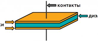
The absolute encoder (Fig. 2.55) does not lose its value when power is lost and does not require returning to the initial position.
The absolute encoder signal is not subject to interference and does not require precise shaft alignment. In addition, even if the encoded signal cannot be read by the encoder, if, for example, the shaft rotates too quickly, the correct rotation angle will be recorded when the rotation speed decreases. The absolute encoder is vibration resistant.
Rice. 2.55. Design of an absolute single-turn encoder
The absolute encoder disk (Fig. 2.56) differs from the stepwise encoder disk because it has several concentric tracks. Each track generates a unique binary code for a specific shaft position.
Rice. 2.56. Absolute encoder code wheel
Binary code is a multi-step code. This means that when moving from one position (value) to another, several bits can change at the same time. For example, the number 3 in binary code is 011. The number 4 in binary code is 100. Accordingly, when moving from 3 to 4, all 3 bits change their state to the opposite simultaneously. Reading such a code from a code disk would mean that, due to inevitable variations in the production of the code disk, the change in information from each of the individual tracks would never occur simultaneously. This, in turn, would result in briefly providing incorrect information when moving from one number to another. So, during the above-mentioned transition from the number 3 to the number 4, a short-term output of the number 7 is very likely, when, for example, the most significant bit during the transition changed its value a little earlier than the rest. Thus, the use of ordinary binary code can lead to large errors, since two adjacent code combinations may differ from each other not in one, but in several digits. To avoid this, a so-called one-step code is used, for example, the so-called Gray Code. The Gray code is preferable to the usual binary code in that it has the property of continuity of a binary combination: a change in the coded number by one corresponds to a change in the code combination in only one digit. It is built on the basis of binary according to the following rule: the most significant bit remains unchanged; each subsequent bit is inverted if the previous bit of the original binary code is equal to one. This construction algorithm can be formally presented as the result of adding modulo two the original combination of binary code with the same combination, but shifted one bit to the right. In this case, the rightmost digit of the shifted combination is discarded.
Thus, Gray Code is a so-called one-step code, because When moving from one number to another, only one bit always changes. An error when reading information from a mechanical code disk when moving from one number to another will only lead to the fact that the transition from one position to another will be only slightly shifted in time, but the issuance of a completely incorrect angular position value when moving from one position to another is completely eliminated .
Another advantage of Gray Code is its ability to mirror information. So, by inverting the most significant bit, you can simply change the direction of counting and, thus, match the actual (physical) direction of rotation of the axis. The output value can be increasing or decreasing for the same physical direction of rotation of the axis.
Since the information expressed in Gray Code is purely encoded in nature and does not carry real numerical information, it must first be converted into a standard binary code before further processing. This is done using a code converter (Gray-Binar decoder), which, fortunately, is easily implemented using a chain of “exclusive or” logical elements in both software and hardware.
From the table 2.3 shows that when moving from one number to another (neighboring), only one bit of information changes its state if the number is represented by a Gray code, while in a binary code several bits can change their state simultaneously. Gray code is an output, hence it never has a read error and is used in many absolute encoders.
Table 2.3
Binary to Gray code conversion table
| Decimal code | Binary code | Gray code |
| 23 22 21 20 | ||
| 0 1 2 3 | 0 0 0 0 0 0 0 1 0 0 1 0 0 0 1 1 | 0 0 0 0 0 0 0 1 0 0 1 1 0 0 1 0 |
| 4 5 6 7 | 0 1 0 0 0 1 0 1 0 1 1 0 0 1 1 1 | 0 1 1 0 0 1 1 1 0 1 0 1 0 1 0 0 |
| 8 9 10 11 | 1 0 0 0 1 0 0 1 1 0 1 0 1 0 1 1 | 1 1 0 0 1 1 0 1 1 1 1 1 1 1 1 0 |
| 12 13 14 15 | 1 1 0 0 1 1 0 1 1 1 1 0 1 1 1 1 | 1 0 1 0 1 0 1 1 1 0 0 1 1 0 0 0 |
Pulse encoders
These types of encoders are designed to indicate the direction of movement and/or angular movement of an external mechanism. The step encoder periodically generates pulses corresponding to the angle of rotation of the shaft. This type of encoders, unlike absolute encoders, does not generate output pulses when its shaft is at rest. The step encoder is connected to a counting device, this is necessary to count pulses and convert them into a measure of shaft movement.
A stepwise optical encoder consists of the following components: a light source, a mark disk, a phototransistor assembly, and a signal processing circuit. The step encoder dial is divided into precisely positioned marks. The number of marks determines the number of pulses per revolution. For example, if the disk is divided into 1000 marks, then in 250 pulses the shaft should rotate 90 degrees.
A step encoder can be classified into a single-phase type (channel output only), which can be used to read the sum of pulses or detect acceleration. By considering the interval between pulses and the quadrature of the encoder (channels A and output B), you can also determine the direction of rotation of the shaft (clockwise or counterclockwise). The zero output index type (N channel) outputs a zero mark pulse per revolution to correct errors within each revolution. Higher resolution (two or four) is obtained by counting both the leading and trailing edges of the marks. Channel A and B generate pulses with phases shifted relative to each other by 90 degrees.
2.12.4. Operating principle of pulse encoders with angular movement
The operating principle of angular displacement transducers is based on recording the relative magnitude of the optical radiation flow passing through the raster interface as a coordinate-periodic function of the relative angular position of the regular scale raster and the analyzer window rasters.
The converter (Fig. 2.57) has two kinematically related functional links: a radial raster scale 1
, rigidly connected to the converter shaft, and a raster analyzer
2
of a fixed reading node.
The radial raster scale (hereinafter referred to as the dial) contains two concentric information tracks: a regular raster and a reference mark 8
.
The raster analyzer contains incremental readout windows and a reference mark 10
.
The windows are positionally coordinated with the track of the regular limb raster and have rasters inside with a pitch equal to the pitch of the regular limb raster. In this case, in each pair of windows, the rasters are shifted relative to each other by an amount equal to half their pitch, and the mutual spatial shift of the rasters between pairs of windows is a quarter of the raster pitch. A transparent window 9
.
The reference mark 10
is positionally aligned with the dial reference mark track. The reading node solves the problem of implementing optical raster and code interfaces that informatively correspond to the magnitude of the angular movement, and the task of reading, processing and analyzing the current values of the optically informative parameters of these interfaces.
Rice. 2.57. The device of a pulse angular encoder: 1
– radial raster scale;
2
– raster analyzer;
3
,
4
– emitting diodes;
5
,
6
– quadrant photodiodes;
7
– condenser;
8
,
10
– reference marks;
9
– transparent window
Structurally, these problems are solved by the incremental unit of the displacement transducer. The first of them is solved by the mechanical part of this unit, ensuring the necessary accuracy of the raster interface between the dial and the analyzer, as well as the coaxiality of the latter with respect to the axis of rotation of the shaft. The second is implemented by illuminators, photodetectors and an electrical circuit board for isolating and processing information about movement. Emitting diode 3
, condenser
7
, which forms a parallel beam of illuminator rays, analyzer windows and photodetector
6
form the so-called reading channel. The requirement for increased accuracy of displacement transducers dictates the use of two or four diametrically located reading channels.
2.12.5. Operating principle of linear motion transducers
The operation of linear displacement transducers (Fig. 2.58) is based on the method of optoelectronic scanning of line rasters. When the scale moves relative 1
and analyzer
3
, pairing the regular scale raster with the analyzer rasters modulates the radiation fluxes passing through them, perceived by the corresponding photodetectors. The raster scale contains two parallel information tracks: a regular raster and reference marks.
Rice. 2.58. The device of a pulse linear encoder: 1
– scale;
2
– photodetector board (silicon photodiodes);
3
– raster analyzer (indicator plate);
4
– illuminator board (infrared emitters)
The raster analyzer contains 4
incremental reading windows and reference mark window B. The above 4 windows are positionally coordinated with the track of the regular scale raster. The raster steps in the windows are equal to the steps of a regular scale raster (20 µm or 40 µm). In this case, in each pair of windows, the rasters are shifted relative to each other by an amount equal to half their pitch, and the mutual spatial shift of the rasters between pairs of windows is a quarter of the raster pitch. A transparent window is located in series with the raster windows. Reference mark B is positionally coordinated with the track of reference marks of the scale (Fig. 2.59).
Rice. 2.59. Linear encoder scale
The reading node (reading head) of the displacement transducer solves the problem of implementing optical raster and code interfaces that informatively correspond to the magnitude of linear movement, as well as the task of reading, processing and analyzing the current values of the optically informative parameters of these interfaces.
Structurally, the first problem is solved by a carriage rigidly connected to the analyzer, which is in constant contact with the scale through rolling bearings, which makes possible relative movement of the scale and the analyzer. The second task is implemented by photodetector boards 2
and illuminators
4
installed on the same carriage, and an electrical circuit board for isolating and processing information about movement, located in the reading head housing.
The illuminator board contains six emitting diodes that provide illumination of the corresponding windows of the analyzer, and spatially coordinated receiving pads of six photodiodes of the board 2
.
Basic parameters required to select an encoder:
number of pulses per revolution (usually from 1 to 5000);
number of bits for absolute encoders (usually 10, 12, 13, 25);
diameter of the shaft or shaft hole;
type of output signal (HTL, TTL, RS422, binary and Gray code, SSI, Profibus DP, CAN, etc.);
supply voltage;
cable length and connector type;
additional requirements for fastening (the need for a coupling, mounting flange, mounting rod, etc.).
Nowadays, hollow shaft encoders are becoming more common - they are easier to install, more convenient to configure and maintain. It should be noted that the service life of the encoder with proper installation and connection should be at least 50,000 hours, i.e. almost 6 years.
2.13. Sensors for technological parameters of textile production
2.13.1. IR moisture meters for fibrous materials
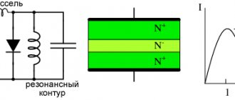
Beam methods for measuring the moisture content of fibrous materials (FM) are implemented mainly in two ways: by the radiation flux reflected from the FM surface or by its absorption when passing through the FM layer, i.e., by attenuation of the radiation flux [16]. In Fig. Figure 2.60 shows the curves for the logarithms of the coefficients of reflection (curve 1) and transmission (curve 2) of IR radiation through VM with constant humidity and increasing density, from which it can be seen that the intensity of the reflected IR flux for the surface density of VM up to 100 - 150 g/m2 increases. With a further increase in the CM density to more than 150 g/m2, the intensity of the reflected flux remains virtually unchanged.
Rice. 2.60. Dependence of the intensity of reflected and transmitted IR radiation on the surface density of the material under study with constant humidity
To reduce the influence of material density on the results of VM moisture measurements, dual-wave single-beam moisture meters with separated radiation sources (LEDs) with an analytical radiation wavelength of l1 = 1.93 µm and a reference wavelength of l2 = 1.76 µm are used. A generalized diagram of such a moisture meter is shown in Fig. 2.61. This scheme was taken as a basis when using a flat light guide as an OEP.
The moisture meter sensor consists of a photodetector 1
with a preamplifier and two LEDs
2
and
3
connected by a light guide
4
, which forms an optical channel
5
for measuring the humidity of the material under study.
The moisture meter works as follows [18]: LEDs through power amplifiers 6
and
7
are alternately connected to the switching power supply
8
, which also controls the operation of the keys of the selection circuit
9
.
The photodetector 1,
through the light guide
4
and the optical channel
5
with the material under study, receives successive pulses of the light flux of the reference and analytical wavelengths, which are converted into a sequence of electrical pulses and , supplied to the amplifier
10
and then through the selection circuit
9
to the recording device
11
.
The passage of the signal through the selection circuit is determined by the threshold element 12
, which is in the humidity control mode in the first stable state.
Threshold element 12
opens keys
13
and
14
and closes keys
15
and
16
.
Rice. 2.61. Scheme of a two-wave single-beam moisture meter with separated LED radiation sources
When removing the material under study outside the optical channel 5
automatic stabilization of the parameters of the reference and analytical signal channels is carried out, regardless of the influence of the environment and the aging of device elements.
This is done as follows. The signal at the output of amplifier 10
increases to the maximum value, which corresponds to the light fluxes and.
This signal throws the threshold element 12
into a second stable state so that the keys
15
and
16
open and the keys
13
and
14
close.
In this case, the values and are stored in memory cells 17
and
18
, respectively, and the result of the last value of controlled humidity is stored on the recording device.
Sequence of electrical impulses from the amplifier 10
is divided by keys
15
and
16
, controlled by the switching power supply
8
, into components and, which are supplied to memory cells
19
and
20
, then respectively to comparison blocks
21
and
22
, where they are compared with the reference signal.
The mismatch signals from the comparison units arrive at the control inputs of power amplifiers 6
and
7
and determine the amplitude of the LED power pulses. The autotuning system thus maintains the emission of the LEDs so that the signals are constant and equal, regardless of the influence of external factors.
When introducing the material under study into the optical channel 5
the signal level at the output of the amplifier
10
decreases, which causes the threshold element
12
to the first stable state.
In this case, the values are stored in memory cells 19
and
20
and, thus, during humidity control, the light fluxes incident on the material under study are maintained equal and .
The calibration characteristic of a moisture meter is the dependence of the device readings on the moisture content (humidity) of the material being tested.
Main settings
The main parameter of any encoder is resolution, that is, the number of pulses (for an absolute converter - bit depth, or number of bits) per revolution. Converters with a resolution of 1024 pulses per revolution are quite often used.
Other parameters:
- supply voltage – from 5 to 24 V
- shaft type – solid, hollow, without shaft (through hole)
- shaft or hole diameter
- output type – usually an open collector transistor output
- case size, type of fastening and degree of protection are also taken into account
The size of the case, the type of fastening and the degree of protection are also taken into account.
Application of incremental encoders
The use of incremental encoders is advisable in any powerful electric drives of precision motion systems or systems that are critical to speed and starting-braking modes. Such drives require accurate information about the movement parameters of the working body:
- in drives of machines for the production of paper and cardboard;
- in devices of any type of packaging and dosing;
- in drives of logging and woodworking machines;
- in drives of rolling production equipment: crimping rolls, roller tables, tilters, tippers;
- in drives of cranes, lifts and elevators;
- in drives of metalworking machines, drilling and construction equipment;
- in robotic complexes and conveyors in assembly plants, etc.
The attractive aspects of using incremental encoders are their versatility with a wide selection of standard sizes, relative low cost and ease of installation.
The choice of an incremental encoder for the purpose of integrating it into the control system of a technological object involves solving the following main issues:
- measurement accuracy - the number of pulses per revolution of the encoder shaft;
- diameter and type of encoder shaft, the need for additional couplings, flanges, etc.;
- cable length and type of output connector, degree of device protection;
- supply voltage, type of output signal;
- issues of signal communication between the encoder and the system: the need to program the encoder, software coordination of the cyclic transmission of measurement results with the sampling frequency of the inputs of the controller used or working in a standard interface, etc.
The obvious complexity of a complex technical solution with the need for certain savings requires significant erudition and experience in solving such situations. Take advantage of the help and advice of specialists. They will study the problem, advise on the equipment you are interested in and offer optimal solutions.
You can select and buy an incremental encoder in the RusAutomation online store...
Installation
The encoder is mounted on a shaft, the rotation parameters of which are measured. For installation, a special adapter coupling is used to compensate for possible misalignment with the encoder shaft, while its housing must be rigidly fixed.
Another mounting option is suitable for hollow shaft drives. In this case, the shaft, the rotation parameters of which are to be measured, directly enters the converter and is fixed in a hollow sleeve or in a through hole. In this case, the encoder body is not fixed, with the exception of some kind of plate or stop that prevents it from rotating.