DRL lamp connection diagram
The mercury arc lamp (MAL) has another name - arc mercury phosphor.
They belong to the category of high-pressure lamps and are used mainly as general lighting for areas with large volumes: streets, playgrounds, industrial premises, etc. The DRL lamp design allows for high light output. Power ranges from 50 to 2000 watts, they operate at alternating current, voltage 220 volts and frequency 50 hertz. In order to coordinate the technical characteristics with the power source, ballasts are used in all types of mercury lamps, which allow the DRL lamp to be connected correctly. Most lighting devices are started by a choke, which is connected in series with the light bulb.
What is a DRL lamp
The abbreviation DRL stands for “mercury arc lamp”. Sometimes the abbreviation RL is found. In some documents, the letter “L” means “luminophor”, since it is the main light source in the device. The element belongs to the category of high pressure gas discharge lamps.
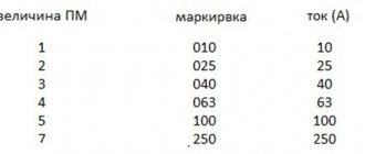
The marking of a specific model contains a number indicating the power of the equipment.
DRL power 400 W
Design and principle of operation of DRL
A classic DRL lamp consists of main electrodes, ignition or additional electrodes, lead-in parts of the electrodes, special gas, posistors and mercury. Argon is used as a gas, which produces initial ionization and contributes to the formation of an arc discharge. Argon is also called a buffer gas. Using posistors, the current of the igniting electrodes is limited. Mercury is used to change the potential during discharge.
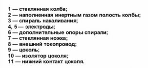
The main functional parts of a conventional DRL
- A base that directly receives electricity from the network. Its contacts are point and threaded, connected to the contacts of the cartridge. Thus, alternating current is supplied to the lamp electrodes.
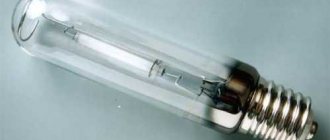
- The quartz burner is the main part. It is made in the form of a flask with four electrodes located on the sides, including two of them - the main ones, and the other two - additional ones. The space inside the burner is filled with argon to prevent heat transfer, as well as a small amount of mercury.
- The glass bulb is the outer part. It houses a quartz burner inside, to which conductors are connected from the base. Instead of air, nitrogen is pumped into the flask. The inside of the flask is coated with a phosphor.
The operating principle of DRL is quite simple. Power is supplied from mains voltage. After the DRL lamp has been connected, the electric current begins to reach the gap between both pairs of electrodes located at opposite ends of the lamp. A small distance between them promotes rapid ionization of the gas. First, the gas is ionized between the igniting electrodes, then the current flows to the main electrodes and at the end of this process the lamp begins to emit light.
The lamp begins to glow fully after approximately 7-10 minutes. This period of time is required to heat up the mercury located in the form of a deposit or clot on the inner walls of the flask. During operation, the service life of the lamps gradually decreases, and the period required for full activation increases.
The burner is made of transparent material - quartz glass, filled with inert gases in strictly defined doses. Mercury introduced into the burner may have the form of a small ball, and also settles on the walls and electrodes in the form of plaque. The light source is an electric arc discharge.
The DRL lamp circuit is included in the general connection circuit via a choke. The choke brand must match the lamp power. The main purpose of the inductor is to limit the current flowing to the light bulb. If there is no choke, the lamp will instantly burn out, since the external electric current is too large for it. Typically, a capacitor is also added to the circuit, which affects the reactive power at startup, which allows you to save electricity almost twice.
The greatest glow occurs after approximately 6-7 minutes. This time is necessary to transform the mercury into a gaseous state, which improves the discharge between the electrodes. After this, the lamp goes into normal operating mode with the highest light output. After turning off the light bulb, it should not be turned on until it has completely cooled down.
Connection diagram for a street utility lamp and its characteristics
Hello, dear readers of the Electrician's Notes website.
In the article about the overhaul of the electrical wiring of a residential building, I said that we installed street lamps ZHKU02-70-003 UHL1 “Pegasus” for the external (canopy) lighting of the entrances.
Today I decided to tell you about the connection diagram for these lamps and their technical characteristics. By the way, at our enterprise they are installed as lighting for central roads, pedestrian paths and production areas. I installed the same lamp at my dacha to illuminate the yard.
These lamps have found wide application not only in industry and everyday life, but also in agricultural activities, for example, for lighting greenhouses and greenhouses when growing various types of plants.
First of all, let's start with the decoding of the abbreviation ZhKU02-70-003:
- F - type of lamp HPS (Arc Sodium Tubular)
- K - console installation method
- U - intended for street (outdoor) lighting
- 02 - episode
- 70 - rated power of the HPS lamp (W)
- 003 - with protective glass
See the table for other technical specifications:
This lamp can be operated within the following temperatures: from -60°C to +45°C. The service life is 10 years.
Here are its overall dimensions.
And this is the appearance.
The lamp has a metal body painted with special anti-corrosion powder paint.
The installation bracket has a diameter of 48 (mm). It is mounted on a wall or other surface, preferably at a height of 5-8 (m). The lamp is installed at an angle of 15-20 degrees to the horizon, although in principle, the angle of inclination can be not only within these limits.
The protective heat-resistant glass is made of polycarbonate. It is very durable, one might even say “vandal-proof”, and it does not change its light transmittance when exposed to direct rays of the sun (ultraviolet).
The glass is attached to the lamp body with three latches and using a mounting tape or chain (in the photo below there is a screw for the tape or chain near the top latch). This is very convenient, because... When replacing a lamp, there is no need to hold the glass in your hands - your hands are completely free.
At the base of the protective glass there is a rubber gasket. It gives good sealing to the optical part of the lamp (IP53).
How to connect a street lamp for housing and communal services
Take the HPS lamp and carefully screw it into the socket.
Pay attention to the cartridge - it is standard with size E27.
The ZHKU02-70-003 luminaire can be equipped with high-pressure sodium lamps DNaT 70-4 or DNaT 70-6. The difference between them is only in the luminous flux and overall dimensions of the flasks themselves. Power 70 (W).
We used Osram VIALOX NAV-T 70W E27 lamps:
Here are its characteristics:
- power 70 (W)
- rated voltage 90 (V)
- rated lamp current 0.98 (A)
- ignition voltage 1.8/5 (kVp)
- luminous flux 6000 (Lm)
- color temperature 2000 (K)
- maximum flask temperature 210°C
- mercury content in lamp 19 (mg)
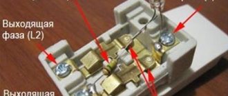
To get to the terminal block, you need to unscrew 2 bolts with plastic heads (wings) and tilt the lamp.
The cores of the power cable are connected to the terminal block of the lamp as follows:
As you can see, the color marking of the wires corresponds to the PUE. Phase (L) must be connected to a terminal with two outgoing white wires, zero (N) - with a blue outgoing wire, and the protective conductor (PE) - in the center.
Now let’s look at the internal diagram of the housing and communal services lamp.
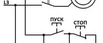
Connection diagram for a lamp for sodium lamps
Due to the design features and operating principle of sodium lamps, when connecting them you need:
There are two schemes for connecting HPS lamps:
In my case, the second scheme is used:
I specifically highlighted the wires in the diagram with the appropriate color, which you will see in the photographs below.
Schematic elements
Let's consider all the elements that are included in this diagram:
1. Ballast (choke)
In general, there are two types of ballasts (chokes):
- electromagnetic or inductive (EMPRA)
- electronic (electronic ballasts)
Each ballast has its own advantages and disadvantages. I will tell you about this in my next articles (in order not to miss new articles, subscribe to the newsletter).
The luminaire in question uses a domestic built-in electromagnetic single-winding ballast (choke) “Galad” 1I70DNaT46N-666 UHL2. It is connected in series with the lamp, thereby limiting and stabilizing its current consumption. By the way, it weighs 1.3 (kg) and its retail price is about 350-390 rubles.
My point is that you should be guided by prices, in case you have to change it, because they often fail. There may be several reasons: an interturn short circuit in the winding, or a break in it.
The throttle body shows its connection diagram and some characteristics.
- power 70 (W)
- voltage 220 (V)
- operating current of lamp 1 (A)
- starting current of the lamp is no more than 1.6 (A)
- power factor 0.38
- current consumed from the network 0.54 (A)
- maximum permissible winding temperature in operating mode 130°C
Connection diagram for DRL lamp via inductor
There are many objects where lighting devices with high luminous power are required. At the same time, they must be economical and have a long service life. DRL lamps fully comply with these requirements. The power of DRL lamps is in the range of 50-2000 W; their operation requires a single-phase network of 220 V and a frequency of 50 Hz.
The most important part of the DRL is the throttle, without which they simply cannot work. The fact is that during the startup process and subsequent operation, these lighting devices come under the influence of variable starting currents and resistances. Therefore, to limit the operating current, the DRL is connected through a choke, which is a heterogeneous ballast in the form of inductors. At the moment of startup they have high resistance. When the lamp is ignited in a gas environment, an electrical breakdown occurs, leading to the occurrence of an arc discharge.
In the process of igniting the lamp, the ionized gas under the action of an arc discharge loses its resistance many times. For this reason, the current increases with the simultaneous release of heat. If the magnitude of the current is not limited, a superheated gaseous environment will instantly arise under its action. Internal parts will be damaged and the lighting fixture will fail completely. To prevent negative consequences, a DRL lamp connection circuit is used together with a choke, which creates the necessary resistance.
Connecting the DRL lamp through a choke, connected in series with the lamp. Its reactance is closely related to the parameters of the inductor. That is, 1 henry of inductance is capable of passing 1 A of current at a voltage of 1 V. The main characteristics of the coil are the cross-sectional area of the copper conductor and the number of its turns, as well as the core material and the cross-section of the magnetic circuit. The magnitude of electromagnetic saturation is of great importance.
How to connect a DRL lamp through a choke?
To ignite and operate the DRL lamp, it is necessary to make the correct connection, which will ensure long-term and safe operation of the light source. The connection circuit is a series connection of the inductor and the lamp. To operate the circuit, a standard household electrical network (220 V, 50 Hz) is used.
What is a throttle for?
The main purpose of the choke in the DRL lamp circuit is to limit the current supplied to the burner. In the absence or direct breakdown of the choke, the gas-discharge lamp will immediately fail because it will not withstand the supply of increased current. When starting and operating a DRL lamp, floating currents and resistance arise in the circuits. The moment of ignition of the arc is especially dangerous, when the ionized gas environment sharply loses resistance, which causes an increase in current strength and increased heat generation.
If there is no DRL current limiter, then an uncontrolled increase in the release of thermal energy will occur, which will lead to the destruction of the burner body and the entire lamp.
In addition, the inductor smoothes out light pulsations, which are especially noticeable when the voltage in the power circuit is unstable.
Throttle design and types
Structurally, the starter is an inductive choke built on a magnetic core in the shape of a rod. The design of the magnetic circuit of the throttle contains adjusting shims made of electrical cardboard. The elements are installed in the air gap, after which the magnetic circuit is fastened using staples or pins.
The operating winding depends on the type of inductor. In the manufacture of devices of the built-in category, PETV copper wire is used; for closed-type devices, PEL winding wire is used. After assembly, the chokes are filled with a thin layer of electrical varnish of the ML-92 type. Products in a casing are installed inside a metal case, which is filled with quartz sand. From above, everything is filled with the KP compound, which ensures insulation of the device.
General view of the throttle
To ignite four-electrode DRL lamps, two types of devices are used:
- Device for use in closed luminaires outside buildings. The starter remains operational in the temperature range from -25°C to +30°C and air humidity up to 90%. The device is not equipped with a separate housing.
- Starter with an individual protective casing, adapted for installation separately from the lighting device. Designed for operation in industrial or warehouse premises in the temperature range from 0°C to +45°C and air humidity up to 85%. There are modifications that can operate at temperatures up to +60°C, as well as versions for outdoor installation separately from the lighting device (designed for temperatures from -25°C to +30°C).
Connection diagram
The choke is installed in a circuit in series with the DRL lamp. The characteristics of the coil are determined by the cross-section of the copper wire and the number of turns wound on the coil. In addition, the material of the magnetic core and its cross-section have an impact on the characteristics. The coil is an integral part of the active resistance of the circuit. This parameter must be taken into account when calculating ballast.
Connection diagram for DRL lamp via inductor
Troubleshooting
If the assembled circuit does not work, then it is necessary to check the serviceability of the elements using a tester switched to ohmmeter mode. It is possible to use a separate ohmmeter. By connecting the device to the terminals of the inductor winding, you can determine the presence of an interturn short circuit (infinite resistance). You should also check the device for breakdown by connecting the ohmmeter probe to the coil terminal and the metal body.
If the choke has an interturn short circuit of several turns, then this does not affect its parameters or the performance of the circuit in any way.
The electronic throttle must be opened and the integrity of the fuse, as well as the tracks and electronic components checked. The measured values are compared with the nominal values from the reference literature.
How to make a throttle yourself?
Self-manufacturing of chokes for DRL lamps is only advisable if a factory product is not at hand.
You can make your own throttling device using standard starting elements from fluorescent lamps. A 40 W DRL choke requires three triggers or two with a power consumption of 80 W.
General rules for assembling and operating a homemade device:
- the chokes are connected in parallel, forming a common starting device;
- connections between nodes must have reliable contact;
- connecting wires must have insulation that protects the unit from short circuits;
- It is possible to install throttle elements in a common box.
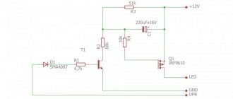
Circuit diagram with a homemade choke consisting of three starters for fluorescent lamps
Connecting a DRL lamp without a choke
Sometimes DRL without a choke can be launched using special technology. This is done in cases where the device has broken down and there is nothing to replace it at the moment. Instead of a choke, you can use a regular incandescent lamp, which has the same power as the DRL and provides the necessary resistance. Another option involves installing one or more capacitors. This will require accurate calculations of the current they produce, which fully corresponds to the required voltage for operation.
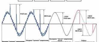
Recently, special DRL-250 lamps have appeared that operate without a choke. Their design contains a spiral of a certain type, which acts as a stabilizer and additionally dilutes the emitted light flux.
Sometimes the lamp refuses to work after connection or does not work correctly. In this case, the lamp must be tested to ensure its functionality. For this, an ohmmeter or tester is used, with which all windings are checked for open or short circuit. If they are detected, the device will show an abnormal value.
What is a DRL lamp
First of all, it is worth understanding the name, because it is by this name that the master determines the characteristics and working conditions. The abbreviation DRL can be deciphered as follows:
- D – ignition type. The source ignites under the influence of an electric arc, which is formed when voltage is applied.
- R – mercury.
- L - the conversion of ultraviolet glow into visible light is carried out using a phosphor.
Also in the marking after the letters you can see a digital three-digit code. It shows the power for which the lamp is designed. On sale you can find devices with a power of 150 W, 200 W, 250 W, 400 W and other load values. In everyday life, light bulbs of 250 W and 400 W are usually used.
Correct connection of the DRL lamp
A high-pressure mercury arc lamp is one of the types of electric lamps. It is widely used to illuminate large objects, such as factories, factories, warehouses and even streets. It has a high light output, but does not have a high degree of quality and the light transmission is quite low.
Such devices have a very wide power spectrum, from fifty to two thousand watts, and operate from a standard network of 220 volts, at a frequency of fifty hertz.
Design and principle of operation
The work is carried out thanks to a starting and regulating device consisting of an inductive choke.
DRL lamp device diagram
This device consists of three main components:
- The base is the base and connects to the network.
- The quartz burner is the central mechanism of the device.
- The glass bulb is the main protective shell made of glass.
The operating principle of such a device is very simple; mains voltage is applied to the lamp. The current reaches the gap between the first and second pairs of electrodes, which are located at different ends of the lamp. Due to the short distance, gases are easily ionized. After ionization in the spaces between the additional electrodes, current flows to the main ones, after which the lamp begins to glow.
The lamp lights up to its maximum in about seven to ten minutes. This is due to the fact that mercury, which emits light when ignited, is located in a clot or coating on the walls of the flask and it needs time to warm up. The period of full inclusion increases after some time during operation.
Drl lamps are classified according to the shape of the base, power, and installation principle. Very often they are made from different materials, which can also be a classification of devices. There are varieties with the addition of special vapors to the design, for example, sodium lamps, metal halide and xenon lamps.
There is a variety with additional emission of the red spectrum of light. They are called mercury-tungsten arc. Their appearance is absolutely no different from the standard drl 250 device, but in their design they have a special incandescent spiral, which adds the red spectrum to the light flux.
What is a throttle for?
The choke for DRL lamps is used for starting; there are different types of lighting devices on the market in which it is used:
- Fluorescent and ultraviolet lamps.
Ultraviolet lamp Various types of mercury arc lighting devices: DRT, DRL, DRIZ, DRSh, DRI.
Arc mercury lamps Arc sodium lamps: DNaMT, DNaS, DNaT. Arc sodium lamp
All lighting devices have differences in the principle of obtaining light flux, there are other differences:
- different materials are used in their design;
- differ in the presence of chemical elements;
- inside the flasks there is pressure according to the own parameters of each lighting device;
- they differ in power and brightness of the light flux.
These types of lamps are united by the variable value of the starting current and resistance during the start-up process and further operation.
In order to limit the amount of operating current, different types of ballast are used in lighting devices of this type: electronic ballasts, ballasts and ballasts, which are inductor coils (chokes). At the moment of startup, each device of this type has a high resistance value; when the lighting device is ignited, a process of electrical breakdown occurs in the inert gas environment with which the lamp is filled (mercury or sodium vapor), and an arc discharge occurs.
During the process when the lamp is ignited, the ionized gas loses resistance from the arc discharge several tens of times, and for this reason the current increases and heat is released. If you do not limit the amount of current, it will instantly create a superheated gas environment, which will lead to breakdown of the lighting device and damage from the inside. To prevent this, a resistance (choke) is included in the lighting device circuit.
Physical parameters and connection diagram of the inductor
A DRL inductor connected in series has a reactance, the value of which depends on the inductor: one Henry passes one ampere of current when the voltage is one volt.
Throttle
The parameters of the inductor include:
- square of copper wire used;
- number of turns;
- what is the core and cross-sectional size of the magnetic circuit;
- what electromagnetic saturation.
The inductor has an active resistance, which is always taken into account when calculating the ballast for each type of lighting device of this type, taking into account its power; the overall dimensions of the inductor depend on this.
Let's consider a simple circuit for switching on the ballast, when the design of the DRL lamp provides (additional) electrodes for the process of occurrence of a glow discharge that turns into an electric arc.
DRL lamp connection diagram
In this case, inductance limits the amount of operating current in the lighting device.
Connection diagram via inductor
In order for the DRL lamp to work properly, the correct connection diagram for this device is necessary. Thanks to proper installation, lighting such a llama will not be any problem, and it will always work efficiently and without failures.
In addition, an incorrect connection increases the risk that the device will deteriorate and burn out ahead of time or at all, when first turned on.
The connection diagram is quite simple and represents a circuit of a series-connected inductor and the DRL 250 device itself. The connection is made to a 220 volt network and operates at a standard frequency. Therefore, they can be easily installed on a home network. The throttle works as a stabilizer and work corrector. Thanks to it, the light source does not flicker, operates continuously, and even with an unstable input voltage, the luminous flux remains unchanged.
Checking functionality
If, after connecting, your lamp does not want to work or does not work correctly, you should check it and test it to make sure it is working properly. To do this, a special tester or ohmmeter will help you.
With their help, it is necessary to check all turns of the winding for breaks or short circuits between adjacent turns. If the circuit has an open circuit, then the resistance will be infinitely large and the meter will show an abnormal value. In this case, it is necessary to completely replace the winding.
If there is no break, but there is a loss of insulation due to which a short circuit occurs, the resistance will increase slightly. If a small number of turns interact with each other, then the increase will be insignificant.
If the short circuit occurs in the inductor winding, then there will be virtually no increase in resistance and this will not affect the operation of the device in any way. After checking the entire winding with an ohmmeter or tester and finding no problems, you need to look for the problem in the light bulb itself or in the power supply system.
We start the lamp without a choke
If you want to use the drl 250 model as a normal device without using a standard choke, it can be connected using special technology.
The simplest connection option is to purchase a special drl 250, which can work without a throttle. It is equipped with a special spiral that acts as a stabilizer and further dilutes the emitted light.
One option not to use a choke is to connect a regular incandescent lamp to the circuit. It must have the same power as the DRL in order to produce the necessary resistance and supply voltage to the DRL 250 light source.
Another option to remove the inductor from the structure is to install a capacitor or group of capacitors. But in this case, it is necessary to accurately calculate the current they produce. It must fully comply with the required voltage for operation.
Types of DRL
There are several main types of DRL lamps:
- Standard mercury arc fluorescent - characterized by weak color rendering, and during the glow a large amount of heat is released. It takes about five minutes from the moment it is plugged into the network to reach operating mode. They are extremely unstable to voltage surges, so operation is permissible in circuits with a constant power source. Designs that use these lamps must have heat-resistant wires.
- Arc mercury erythema tungsten (DRVED) is a lamp that operates without a choke. Connects via active ballast in the same way as standard incandescent light bulbs. Due to the presence of metal iodides, light transmission increases and energy consumption decreases. For greater brightness, uviol glass is used. Best suited for rooms with little natural light.
- DRLF is an improved DRL used to accelerate plant photosynthesis. The inside of the bulb is covered with reflective material, which is why the light bulb got its second name - reflector. Ideal for AC connection. It is used in greenhouses and greenhouses where an additional light source is required.
- Arc mercury tungsten - increased luminous efficiency, long service life without a ballast. An excellent option for lighting streets, parking lots, open areas, etc.
Types of lamps
DRL type luminaires are characterized by a wide variety. The differences are in the area of application (internal, external), types of structures and power of devices.
Standard sizes of mercury lamps for indoor use
Domestic
Luminaires with fluorescent lamps are recommended for lighting production facilities with high levels of dust and moisture, as well as laundries, car washes, closed warehouses, and garages. The devices operate from an alternating current network with a frequency of 50 Hz and a rated voltage of 220 V. The ambient temperature during operation is -20°C to +50°C.
Street
External lamps are used for direct, diffused, local lighting, and are successfully combined with symmetrical or asymmetrical reflectors. The street lamp of the DRL type is enclosed in a waterproof durable casing and is able to withstand strong winds, frosts and downpours.
Classification of lamps by lamp type:
- DRL. The products are characterized by a low color rendering index, heat generation, and 5-minute output to the required level of luminous flux. When choosing mercury products, it is also worth considering the need for a stable energy source and heat-resistant conductors.
Light source for plants
- DRLF. Lamps with focused light are characterized by their ability to stimulate photosynthesis in plants.
- DRVED. The series of mercury arc erythema tungsten lamps does not require the connection of ballasts. Activation occurs under the influence of ballast, similar to conventional incandescent lamps. The design is based on metal iodides, which ensure the desired level of color. The lamps emit UV (erythemal) radiation and operate effectively with alternating current. They operate without ballasts, achieving a maximum luminous efficiency index and a long service life. Lamp power ranges from 125-1000 W.
Sodium Arc Light Sample
- DNAT. The principle of operation of a sodium arc tube lamp is similar to DRL lamps. However, HPS lamps have a specific glow and light of an orange-yellow or golden-white hue. The devices consume 70-400 W of power and are considered the most economical light sources.
You may be interested in this Rating of the best infrared heaters
Important! The most popular and widely used are DRL lamps with a power of 250 and 400 W.
Device
The shape of the product is oblong, reminiscent of ordinary incandescent light bulbs. But there are certain design differences between them.
The DRL includes the following elements:
- a glass bulb is something that almost all light sources have. Used to protect internal parts;
- metal base - used for screwing into the lampshade of an electrical appliance;
- a tube filled with mercury vapor. It is placed inside a glass flask and is made of quartz glass. Usually mercury is diluted with argon;
- lamps can be equipped with secondary electrodes and cathodes. This speeds up the ignition of the product, reaching the operating mode and increases stability;
- A carbon resistor is needed to connect the electrodes and cathodes.
Lamp device
A luminescent counting source is a lighting device in which ultraviolet radiation is converted into visible light of a certain spectrum. The glow is achieved thanks to an electrical discharge that appears when electricity is supplied in a gaseous environment. Ultraviolet light is generated, which affects the phosphor. As a result, the light bulb lights up and begins to shine.
Most fluorescent lamps are manufactured in the form of cylindrical tubes. More complex geometric shapes of the flask may be found. Along the edges of the tube there are tungsten electrodes, which are soldered to the outer pins. It is to them that the voltage is supplied.
Structure of a fluorescent lamp
The standard light bulb circuit consists of a starter and a choke. Additionally, various control mechanisms can be used. The main task of the inductor is to generate a pulse of the required size, which can turn on the lamp. The starter is a glow discharge whose electrodes are in an inert gas environment. A prerequisite is that one electrode must be a bimetallic plate. If the lamp is off, the electrodes are open. When voltage is applied they close.
Classification is carried out according to different criteria. The main one is light. It can be day or white with different color temperatures. The division is also made along the width of the tube. The larger it is, the higher the lamp power and the area of the illuminated area. Fluorescent lamps are divided according to the number of contacts, operating voltage, presence of a starter, and shape.
Principle of operation
After connecting the electrical element to the network, voltage through the base is supplied to all electrodes, due to which a glow discharge is formed. Positive ions and free electrons appear inside the flask. After reaching a given level in the number of charges, an arc discharge is formed instead of a glow discharge. In most cases, all this takes no more than one minute.
It will take about five minutes for the DRL lamp to operate at its maximum light parameters. This is due to the time required for the evaporation of mercury drops placed in the gas-discharge chamber. This improves the brightness of the arc discharge.
The exact time to reach operating parameters is affected by the ambient temperature - the higher, the faster.
Technical and operational characteristics
As the glass flask is heated, the mercury scattered on its surface (in the form of drops) begins to evaporate. The stronger the evaporation process, the stronger the discharge between the electrodes and cathodes. The nominal mode of the DRL lamp is the moment when all drops of mercury are converted into steam.
Important! After disconnecting the power from the lamp, it can only be turned on again after it has completely cooled down.
The product is characterized by increased sensitivity to temperature changes, so its functionality without a flask is impossible (based on physical laws).
The flask is responsible for two important functions:
- Barrier between the gas-discharge chamber with mercury vapor and the environment.
- Acceleration of the process of converting ultraviolet rays into a red light spectrum, which is possible due to the presence of phosphor on the walls. To the red glow is added green, generated by an internal discharge, which leads to the appearance of white light.
Voltage surges greatly affect the operation of the DRL lamp. A deviation from the nominal value of 10–15% is considered acceptable, but if this value is equal to 25–30%, the glow will become uneven. With an even greater reduction, the lamp will either not light up or go out (if it was in operation before).
Decoding product markings is very simple - the number indicates the lamp model, which coincides with the rated power.
The table below shows the parameters of specific DRL models:
| Model | Rated voltage, V | Power, W | Length, mm | Diameter, mm | Base | Luminous flux, lm | Durability, h |
| DRL-125 | 125 | 125 | 177 | 77 | E27 | 6000 | 12 000 |
| DRL-250 | 130 | 250 | 227 | 90 | E40 | 13 500 | 15 000 |
| DRL-400 | 135 | 400 | 290 | 121 | E40 | 25 000 | 18 000 |
| DRL-700 | 140 | 700 | 356 | 151 | E40 | 40 000 | 20 000 |
| DRL-1000 | 145 | 1000 | 412 | 168 | E40 | 60 000 | 18 000 |
Connection diagrams
A lamp consisting of four electrodes is connected in series with the inductor. After connecting the inductor and DRL, mains voltage is supplied to them. When using a choke, polarity does not matter, since its main purpose is to stabilize the operation of the lighting device. The choke must correspond to the specified lamp power. By adding a capacitor to the circuit, electricity savings are achieved and reactive power adjustment becomes possible.
Connection diagram via inductor
The function of the choke is to reduce the current required to operate the light source. In the absence of a choke, the lamp burns out due to high voltage. The elements are connected in series.
Connection diagram without choke
There is a separate technology used to connect DRL without a choke. The ideal option would be to purchase a factory DRL, which does not require a choke. The product is supplemented with a spiral that works like a regular stabilizer and dilutes the light flux.
Also, a regular incandescent light bulb, the power of which is comparable to DRL, can be connected to the circuit. It acts as a resistor that lowers the voltage at the output.
You can add one, two or more capacitors to the circuit. This is relevant if an important condition is met: the current that they will produce at the output must be calculated with high accuracy.
Characteristics
Operating parameters of DRL lamps:
- Light bulb power 80-1000 W. Determined by the number of electrodes: two electrodes - 250...1000 W, four electrodes - 80...1000 W. Devices with a power of 250 W are especially popular.
- Base. Depends on the power: devices up to 250 W are equipped with an E27 base; above 250 W, the E40 option is suitable.
- The clock load of the network reaches 8 amperes. The indicator is interconnected with the power of the lighting device.
- The luminous flux of mercury devices is a minimum of 3 2 00 lumens. The value is typical for an 80 W light source. Street lighting lamps with a maximum power of 1 kW emits a luminous flux of approximately 52,000 lumens.
This might be interesting to you Electric meter Mercury 201Single-line design diagram
Interesting! The operating life of the throttling lamp reaches 20,000 hours. However, the light bulb stops working 30-50% earlier.
Parameters of a 150 W mercury lamp
Checking functionality
To check the performance of the DRL, testers (ohmmeters) are used, which is necessary if the lamp refuses to work or functions incorrectly. Connect the device to each turn on the winding, checking them for open circuit and short circuit current:
- If a break is detected, the device will show a huge resistance, so you will have to replace the winding.
- If there is no break and no loss of insulation is detected (thus creating a short circuit), the difference in resistance will be less significant.
- If there is a short circuit on the inductor winding, an increase in resistance may not be observed and the technical characteristics will remain the same. On the other hand, this fact does not in any way affect the performance of the lamp itself.
If the ohmmeter does not show any deviations, then the problem should be looked for in the lighting fixture or electrical network. The lamp may need repairs.